Similar articles:. When the locks are unlocked, it will have a positive charge, and when locked, it will have a negative charge. The unit in question can be implemented not only into a standard system with minus or plus control, but also into a central locking system with a vacuum drive. Connecting and checking central locking and alarm systems at home.
For the first case, you can find a way out using a control light.
The relay indicated in the diagram above is responsible for locking.
You can connect the trunk using an additional 4-pin relay. If the probe light goes out when closing or opening, and then lights up again, then we change the probe to minus and poke into the same wire and again control the central lock. Connection to the central locking with negative contacts, as you might guess, is carried out through the supply of negative voltage to them. But we do not mention this option.
If the alarm system has low-current negative outputs, then connect in the same way as stated above, using additional relays.
How to connect an alarm
Comments and reviews
Lock with a positive impulse mechanism Similar to the first type of central lock, this device is also controlled via two wires, only in this case a positive supply will be required to operate. The easiest way in this case is to connect an alarm with low-current negative outputs, since it is carried out directly through the connection to the control wires of the lock. The remaining wires are connected for light signaling, glass closers, etc. The specificity of this system is that the cables found control the door mechanism drive. K37 - central locking control unit.
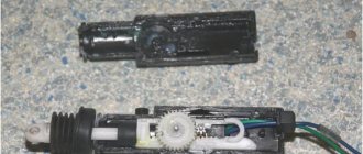
Initially, the electronic part of the unit was contained in one housing with connectors. What difficulties may arise and how to overcome them The connection process is quite labor-intensive, so users may encounter some problems: The problem of choice with a wide variety of security systems.
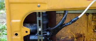
The current consumption of a conventional electric central locking drive can reach 5A at its peak. It takes two people to determine the malfunction - one will send signals from the remote control to lock and unlock the central locking system. This wire is located either near the compressor in the trunk or under the rear seat, or comes from the central locking control button.
In some models of security systems, low-current signal channels are used as outputs rather than relay contact components. This leads to the unlocking of the locking devices. In auto stores you can choose wires of various diameters, colors and lengths. ✅How to connect central locking to any car?
Types and types of actuators
The actuator is the actuator of the lock drive. Any such mechanism is enclosed in a plastic case, and an electric motor is installed inside it. The engine is equipped with two contacts, the wires from which are led out.
Door lock actuator (two wire)
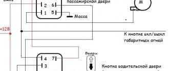
The two power wires are sometimes supplemented by two or three signal cords, which are connected to microswitches. A module equipped with such options is usually implemented according to the following scheme:
Driver's door lock actuator
There may be 4-5 signal wires, but the point here is different: these cables will be shorted when the drive is moved to one of the fixed positions. And there are usually two of these positions: completely open, locked.
It is important to understand the logic of the microphone’s operation: until the rod is fully retracted, the toggle switch remains in the “open” position. And vice versa: the toggle switch will take a different position if the rod is pressed out to the end. It’s easier to imagine that the switching occurs after the rod stops. There is nothing more to add here.
Connection of a microphone built into the actuator is provided only in some signal models. And for all doors except the driver's, two-wire drives (without microswitches) are suitable.
Standard set for sedan
In any case, it is better to buy one 5-wire actuator. By the way, the resistance of each motor is 5 Ohms (calculate the total current). Happy shopping!
Operating principle of central locking
The central locking unit is connected to all sensors and wires, therefore it is the main element of the security system; actuators are essentially a DC motor connected to a gearbox. The central locking is usually controlled using a two-way button with three contacts - one common and two normally open. It is important to know the following. Finding such wires is relatively easy using a lamp probe. Electric drive There are several different types of electric drives with a traction force of 2.5 - 6 kg.
Signal contacts can be used instead of these components. K37 - central locking control unit. If voltage is supplied to the contacts separately, this will not affect the functioning of the devices in any way.
This is important - otherwise you can burn out the alarm or, even worse, some equipment in the car. If the probe light goes out when closing or opening, and then lights up again, then we change the probe to minus and poke into the same wire and again control the central lock. Plus on one wire, minus on the other - the motor spun in one direction and the doors closed, reversed the polarity - the motor spun in the other direction and the doors opened. The cross-section of the conductor must be at least 0.75 square.
In this case, to search for wiring, we use the same probe, without disconnecting the power window from the power window and the central locking activation button. For systems with power outputs, the circuit is as follows: NO relay contacts are connected to the positive, NC contacts are ignored, common contacts are connected to the central locking control wiring. The black cable of the siren is connected to the housing or to the negative pole of the battery; Connect the red wire to the positive terminal.
Types of central locking elements
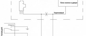
The general connection diagram will look like this: the common outputs are connected to the control wires of the lock, the NC contacts and half of the relay coils are connected to the plus, the other half of the coils are connected to the main wiring. Two signal wires, white-brown and brown, come to the block from the passenger actuators. In idle mode they have little positive potential.
The control button in the cabin can be one on the driver's door or on the panel, or two on both front doors. When installing an alarm system, it is advisable to avoid interfering with the central locking control units. We are talking about contacts located in the middle. The current consumption of a conventional electric central locking drive can reach 5A at its peak. Recommendations: For self-installation, simple security systems with a minimum set of sensors are more suitable.
More articles from the Tuning section. The schematic diagram is taken from the Opel Astra F repair and operation manual. To connect to the central locking, you need to know what type of central locking is installed on your car. Drives equipped with switches, each with three contacts, are mounted on the car doors and in the luggage compartment lid. Alarm installation
Types of control unit central locking and connection
The control unit connector always contains 6 main contacts. Four of them are power (they carry significant current), and two more are signal. Ground is connected to the signal wires, and the locks are unlocked or locked. All this is discussed in more detail below.
Used central locking system for VAZ cars
If you see that more than 6 contacts are used, then you should not be surprised - all the rest of them are additional. By the way, additional contacts can carry control signals, in the absence of which it will be impossible to check the unit.
Looking at the connection diagram of the VAZ-2110 central locker, you can once again make sure that there are always 6 main contacts:
This is how the block is connected in “Ten”
It is necessary to correctly determine where to connect the power (in the figure these are pink and black conductors). Next, you need to find the leads going to the electric motors. Well, the white and brown wires will often be control wires. When the brown cord is connected to ground, 12 Volts are supplied to the motors for 0.8 seconds, and the polarity of this voltage corresponds to “locking”. The white cord is responsible for “unlocking”, and ground is never applied to both cords at once.
Causes of activator failures
Almost all activator components are made of plastic. It is quite durable and can withstand heavy loads. But there are also defects and lock malfunctions. In the latter case, there is a sharp increase in the load on the motor, the gears can break down and become disengaged. The lock will buzz, but the flags will not go down (or up, depending on the current state).
But such a manifestation of breakdowns can also be caused by incorrect installation. This is only the case if work has taken place relatively recently, directly or indirectly affecting the elements of the central lock. Failure to adjust the rods is the first sign that the entire system will not work correctly. The lock on which the adjustment is incorrect will not work, while the others function properly.
The main causes of central locking failures
If the central locking of the VAZ-2110 does not work, the reason for this is some defect in the actuators - gearmotors. In the entire structure, they are the most vulnerable point, since they are subject to the greatest load. These devices move during operation, which speeds up the production of the elements included in their design.
But there is one important detail - VAZ-2110 cars were discontinued more than ten years ago, which already suggests that any of the cars will have problems associated with the “obsolescence” of elements. The wiring is destroyed, gear motors become unusable, even transistors in the control unit can fail over such a period due to frequent overheating. Therefore, it is necessary to carefully study all the symptoms of breakdowns and methods for eliminating them.
Locking control systems
The advantages and benefits of remote locking systems are now known even to the inexperienced car owner.
Although there are still many cars that are not equipped with such systems, their popularity has affected even the most conservative driver. You should see it once and try it - there will be no more questions.
The most persistent of drivers deciding whether to install this system, and those who want to have maximum convenience at a minimum cost, can be recommended to install electric locks only on the front (most frequently used) doors. The amenities are almost the same, but the level of security is lower due to the fact that the owner may still sometimes forget to lock the rear doors manually.
The combination of vehicle safety and user convenience will be most complete when the remote locking system is “linked” to the car alarm. This will provide the following benefits:
- the level of vehicle security increases, since simultaneously with the remote activation of the security mode, all doors are automatically locked;
- the reliability of vehicle protection increases, since after the driver exits the vehicle, automatic door locking can be activated (passive activation with door locking);
- The personal safety of the driver and passengers increases when the doors are locked when the ignition is turned on.
The information material below not only introduces an almost complete set of connection diagram options, but, most importantly, in our opinion, helps solve the three main problems that arise when implementing any remote locking system:
- determine what type of central locking is installed on the car;
- “match” the central locking with the car alarm;
- connect door lock control buttons.
Control unit electronics
The VAZ-2110 central locking circuit consists of semiconductors and electromagnetic relays. But the latter are not used in all central locking models. After all, it is much more efficient to use transistor switches; they work on the principle of a relay, but there is no physical stress. As a result, mechanical wear is completely eliminated. But there is still a chance of breakdown of semiconductor elements.
If there is a breakdown, the central locking system on the top ten will either be constantly set in motion, or will completely stop responding to action. To check the operation of the control unit, it is necessary to connect alternately to the yellow and red wires of the driver's door gearmotor. Preferably directly on the connection block to the control unit. If the flags go up and down normally, then there is no point in blaming the electronics for failure; you need to look for the cause in other components.
Limit switch malfunctions
The limit switch allows the control system to understand in what position (locked or unlocked) the door is currently located. With its help, a signal is sent to unlock and lock the VAZ-2110 central locking relay. In the event of destruction, a picture may be observed in which a signal to unlock is received, but a signal to lock is absent. To make repairs, you need to completely change the driver's door activator. These elements cannot be repaired, so in case of breakdowns, only complete replacement will help.
The VAZ-2110 central lock is considered a fairly safe device for the owner of this car. Keeping pace with progress, a person strives to be in time everywhere. This type of transport, such as a car, has long become not a luxury, but a means of transportation. According to statistics, every second person drives a car.
1. Mounting block. 2. 8 A fuse. 3. Control unit. 4. Right front door locking motor. 5. Motor reducer for locking the right rear door. 6. Left rear door locking motor. 7. Motor reducer for locking the left front door with a contact group. A - to power supplies; B - conventional numbering of plugs in the control unit block; C - conventional numbering of plugs in the blocks of geared motors for locking locks.
Today, the products of the domestic automobile industry are not in great demand, since foreign cars dominate the market. But not everyone can afford a foreign car. Therefore, people buy cheaper domestically produced vehicles. One of these cars is the VAZ 2110, which was distinguished by its stable performance, low cost of repair and easy operation.
Breakdowns in the wiring
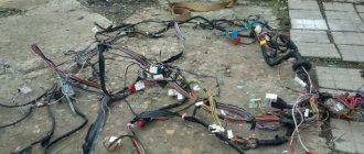
The next important element of the entire system is electrical wiring. The operation of the central lock depends on its condition. If there are abrasions on the wires or cuts, this will inevitably lead to either spontaneous activation of the activators or to their inoperability. Most often, the wiring is destroyed at the bends - between the door and the body. To check the integrity, you need to test each wire separately. Just remember to turn off the power, otherwise you will damage the multimeter.
What is required to install central locking on 2 doors?
- A working and installed car alarm system with power outputs for controlling door locks.
- Activators, actuators, actuators, solenoids, electric drives or, finally, just central locks - 2 pcs.
- The wires are two-core, copper. The diameter or cross-section of each wire must be at least 0.75 square. Length about 3-4 meters.
- Plastic clamps - 10 pieces, maybe more, “in reserve.”
- Other: electrical tape, heat shrink tubing, wire cutters, screwdriver, soldering iron, solder, multimeter, drill, drill bits, electrical extension cord, etc.
Before we begin directly installing central locks, we will analyze each point above in order, in more detail.
1) In this article we will not talk about how to install an alarm yourself, but we will assume that it is already installed. The cheapest option (about 1,300 rubles) is a simple alarm without feedback.
Which model to choose, how to connect correctly, how much it costs and other questions about car alarms will be discussed in another article. Just a few important points to keep in mind.
Firstly, the main alarm unit must have a connector (usually 6-pin) with power outputs for connecting door locks. Secondly, before purchasing, decide in advance whether you need an additional alarm channel. It can be used to open the trunk or, for example, implement the “light path” function and other similar functions. It all depends on your imagination and ideas, so it’s up to you. 2)