VAZ 2109: central locking - purpose, operating principle, installation method
The central locking unit of the VAZ 2109 ensures the safety of the vehicle, which is one of the most important factors for the driver. There are different anti-theft security systems for car safety. An important role is played by installing door locks. The main purpose of the device is to simultaneously close and open doors in a car. In addition, on the VAZ 2109, central locks control the luggage compartment and fuel tank lids.Features of connecting the system to a lock with variable polarity
In this case, the car alarm must be connected directly to the car's power wires, which are again looked for with a probe. First, use it to find the negative power wire (the device should be connected to the positive, and then press the corresponding button on the alarm, determining the required wire). They look for another wire (power) in the same way.
After this, you will need to cut the identified power wires, purchase two relays if we are talking about a car alarm with low-current type outputs, and connect according to the diagram below:
- general contacts - to the wires coming from the driver's doors;
- normally closed contacts - to those wires that go to the lock button or to the central locking unit;
- normally open contacts – to the “plus”.
You have successfully completed the procedure for connecting the alarm to the central locking!
Did you like the article? Follow our channel for new ideas of useful car tips. Subscribe to us in Yandex.Zen. Subscribe.
The problem of how to connect an alarm system to the central locking of a domestic car has been relevant for VAZ owners since 2000. Before this, central locks were not installed at all on Tolyatti models. Now the useful device is offered for basic configurations as an additional option. Realizing the benefits of central locking and car security alarms, many car owners install both devices on domestic cars of all years, especially since self-installation helps save money. VAZ models make up about half of the country's car fleet, and ensuring their safety is of interest to millions of drivers.
Theory
Before starting the installation, I want to warn you about the characteristics of my particular VAZ 2114 car (2006 model year, “Lux” equipment, the wiring under the dashboard is numbered as “VAZ 2115-...”), since I myself, from personal experience, have seen “four” and “tags” of the same year of manufacture, the same configuration, but with completely different wiring (I assume that this was due to different supplies of wiring to the conveyor).
After looking at the information on the Internet, I came to the conclusion that the overwhelming number of people install the control unit according to the incorrect diagram “D”, from the instructions, which will not fit the Samar family (VAZ 2108/09/99/13/14/15) , since the opening and closing of doors (or rather, the supply of a signal to the BUDU (Door Lock Control Unit)) in Samara is controlled by a “minus”, and according to the “D” scheme, control occurs by supplying a “plus” to the BUDU. As I found out, this scheme only works when the standard BUDU is removed and the BU works every other time and only one button on the control key works. In my case, when connecting circuit “D” (I tried to connect it together with the BUBD), I burned several fuses and started looking for another connection method.
Multitronics operating instructions wiring diagram
The videos cover issues related to the initial setup of Multitronics on-board computers. For complete information on all device settings, please refer to the user manual. Performing a master reset. Protocol definition. Video instructions, setting up the Multitronics on-board computer.
Connecting Multitronics to the car, selecting a protocol
Video instruction No. 1 Connecting the Multitronics on-board computer to the car, selecting a protocol, automatically selecting a diagnostic protocol, manually selecting a diagnostic protocol. ..
Sorry, the product is currently out of stock
Free delivery within Krasnoyarsk
News from the Laukar online store:
Additional information in the On-board computer category:
In the online store of household appliances "Laukar" you can download the instructions for the product On-board computer Multitronics TC 750 completely free of charge.
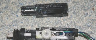
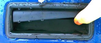
Installing a central lock on a VAZ 2109 car
On the VAZ 2109, installation of the central lock is carried out in two stages:
- Front door lock device.
- Installation of wiring and connection of the main central locking.
Advice: Before carrying out work, it is necessary to change the drive connection wires for the window regulator.
To carry out the work you will need:
- Upholstery holder.
- Corrugated tube.
- Set of central locking elements.
- Knife terminals.
- Set of wires.
- Heat-shrinkable cambric.
It is advisable to install the VAZ 21093 central locking control unit in a garage or other place where no one will interfere. Instructions for doing the work yourself:
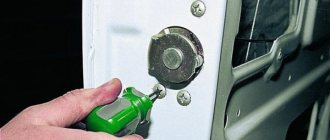
- The screws securing the handle are unscrewed, which is then removed.
- The handle lining responsible for opening the door is removed.
- All operations are repeated for the other door.
- The upholstery is removed. To do this, pry it off from all sides of the doors with a screwdriver.
- The installation location of the locks is determined.
Tip: The best installation location is the lower left corner. In this case, when lowering the glass, it does not touch the lock and does not interfere with the driver.
- Several holes are made.
- The lock is screwed on with self-tapping screws.
- The same actions are performed with the other door.
After carrying out these preparatory work, you can begin installing the door lock rods to the central locking rod:
Tip: The stroke of the lock rod is slightly greater than the length of the central lock rod, resulting in a difference of approximately six millimeters. Therefore, you need to combine the centers of thrust and there will be no problems. Sometimes the thrust from all sides does not reach by about two millimeters. In this case, you need to tighten the screws very firmly, but so as not to damage their heads.
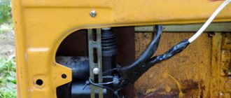
- The dashboard is removed. For this:
- Several points are pierced near the mounting screws.
- The wires are located inside.
- The places of their passage are determined.
- Here, new wires are laid for the central locking, after getting rid of the old elements.
- Connecting the lock wires. In this case, the wire is insulated and pulled into the door.
- After wiring the wires, they are pushed through the holes located under the dashboard.
- A pass-through tube is installed into the rack on each side. Care must be taken to ensure that the tube is not damaged.
- All wires are connected to the connectors.
- The fuse is attached.
- The connector and the central locking unit are connected.
- All wires are hidden under the dashboard.
- The place where to connect the VAZ 2109 central locking in the car body is determined.
Tip: If the wire is not enough, it needs to be extended.
The fundamental difference between the main types of central locking
We strongly recommend that you leave the solution to problems related to electricity if you do not know the principle of operation and the purpose of the connected batteries. Connecting a central locking system is no exception to this rule.
Fundamentally, devices for automatic unlocking/locking of door locks can be divided into 2 types:
- Central locking with electric drive. Electric activators are installed in the doors. Each mechanism can have an individual control unit or be controlled by a single unit (this is the scheme used on budget cars);
- pneumatic central locking. The activator rod moves due to changes in air pressure inside the line. At the moment, the system is outdated and not used; in the past, such systems were installed by Mercedes, BMW, VW, Audi. It is not economically feasible to restore such a system or install it yourself. It is much easier to install electrical activators by connecting everything to a unit with a remote control function.
We will consider central locking with electric drives. Devices of this type are divided into 2 types:
- with positive potential control;
- with negative potential control.
What a control signal is and why it is needed will become clear to you when we look at the operating principle of the simplest central locking system. As an example, let's take the most common scheme on budget cars with minus control. The schematic diagram is taken from the Opel Astra F repair and operation manual.
How does the simplest central locking work?
You can immediately see that a 5-wire activator is installed in the driver's door. Some car manufacturers, wanting to save money, do not install a control servo in the driver's door, but only a button.
What we see in the diagram:
- S41 – limit switch located at the driver's door lock cylinder. When turning the key to unlock or lock, a negative potential is briefly (about 1 second) applied to the central locking unit.
- S42 – passenger front door switch.
- M18, M19, M20, M32 – door activators. M41 – gas tank flap lock, M60 – trunk servo drive; To operate servos, 2 wires are enough, which are called power wires. The potential difference on these wires starts the motor, which moves the lock rod. Depending on which wire has - and which has +, the motor will spin in one direction or the other. The third wire (blue-black) is required by the standard alarm system to monitor the status of the locks.
- K37 – central locking control unit. To operate, the block necessarily requires a constant + and mass. Two signal wires (white-brown and brown) come to the block from the passenger actuators. In idle mode they have little positive potential. The appearance of a minus on one of the wires provokes closing, and on the second - opening. It is this minus signal that determines whether the central locking is controlled by minus or plus. Depending on which wire - appears on, the unit supplies voltage of the required polarity to the power wires.
This is exactly how the simplest central locking works, which does not even react to whether the driver’s door is open or closed. The simplest central locking control unit works according to a circuit of two 5-wire relays. We invite you to watch a video that describes in detail the principle of operation and the method of connecting two-wire activators.
How to implement remote control
The remote control unit from Aliexpress, attractive for its low cost, has recently gained great popularity. Using a block of this type, you can connect a remote control to a standard system or equip a car with a central locking system yourself, having previously purchased 4 two-wire activators. Of course, there can be no talk of protecting the car from theft. Such a budget central locking control unit can only perform a service function.
Pressing a button on the key fob replaces physically turning the key in the lock cylinder to unlock and lock the car. Receiving the signal, the control unit supplies voltage to the power wires. Only 6 wires are responsible for the operation of the unit and car locks:
- constant +, protected by a fuse (in our case - 15A);
- weight;
- 2 power wires going to the servos;
- 2 control wires.
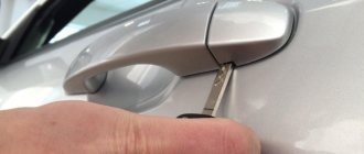
Car alarm installation
Before purchasing, study all kinds of models, select the ones that are suitable for the VAZ-2109.
There are quite a lot of them, they differ in functionality and depending on whether you have a carburetor or an injector installed.
Check for these features:
- turning on the engine from the key fob;
- remote engine stop;
- mechanical impact indicator;
- communication and communication signaling device;
- turning on the alarm whenever the car is opened;
- possibility of canceling the program.
Instructions are included with each device. If you install it yourself, you need to familiarize yourself with it carefully. Even after a high-quality self-installation, there may still be some nuances. For example, a monolithic alarm system is easier to install, mobile, it will not be difficult to install it anywhere on the car, but it is easier to hack if it is stolen.
To install this device, you will need the following devices and tools: a voltage meter with limit data up to 12 V, insulation, Phillips and regular screwdrivers, a wire stripper, a soldering iron, single-core and stranded wires (length up to 10 meters).
Programming the duration of control pulses
Even if the alarm is connected correctly, it is not a fact that the owner will be able to control the locks from the key fob. The point is that it is necessary to correctly select the duration of the control pulse (for locking and for opening). There is no need to make it too large so as not to overheat the actuators.
See what exactly the manufacturer Starline offers. We can set the pulse duration to 0.7 s, which should be enough. The value “3.6” will be redundant at the same time.
The “Lux” package has the following property: after 15 minutes of inactivity, the electronics “fall asleep”. It may take an extra boost to wake her up. So, try to use the option that provides for a double pulse. The main thing is not to activate the “comfort” option, which uses a 30-second duration. To connect the signaling with “comfort”, you need to install an additional unit in Grants (AvtoVAZ does not produce it). We wish you success.
Granta and Starline - all options
I have long been planning to install an additional button for locking/unlocking the central locking in the driver's door of the Lada 2111. I reviewed several articles with photos - they suggest using the same button as for unlocking the trunk. (large, with power contacts).
It is installed into the door handle with difficulty and loss - you need to bend the contacts, trim the moving parts of the opening mechanism. In a word - a completely unacceptable option for me!
A short excursion to radio parts stores and the button was found.
Thread diameter - 12mm Overhang (depth) of the internal part with contacts - 14mm Height (outer) - 8 mm Normally open contact without fixation. Just what you need!
Momentary button
The button is connected parallel to the actuator microphone - brown and white wires that go to the central locking controller (BUBD ITELMA 21093-6512010-03). That's all. The button is connected via additional connector to make it convenient to disassemble the door trim.
Operating principle: depending on the state of the lock (actuator) - open or closed - one of the contacts of the mic is closed to ground. When the button is pressed, the mass is supplied to the second contact, and accordingly to the BUDU controller, which, having received an input impulse, activates the actuator, changing its position to the opposite.
Thus, with just one button, closed-open control is carried out. When you hold the button for a long time, the lock state changes only once.
The BUBD was previously modified - the cause of freezes and glitches was eliminated, and additional inputs were added for the independent functioning of additional buttons. This function is also supported by 6-pin central locking controllers (transistor).
Author; Seklitsky Maxim Nikolaev, Ukraine
I would like to share my experience of replacing the central locking unit with a unit from 2109 (21093-6512010-03)
The car was equipped with a Saturn RTR-6204 central locking system, the original control unit of which failed after about half a year. The task arose to revive the door control.
After a short search, the choice fell on the VAZ 2109 BUBD.
Since their connectors are completely different, I had to delve into the essence of the design. Looking into the BZ to the owner of one Nexia, I found a wiring diagram, redoing it in my own way:
The ground wire was crimped under a new block:
Here's what happened in the end:
BUBD contacts:
1— positive 2— ground 3.4— power control of activators (if the activator is two-pin, then connect only here) 5.7— control of closing and opening (if the activator is five-pin, then the second pair of wires (in my case it is brown, white) goes here, and the fifth (black) goes to ground, you can also connect a separate door unlocking and locking button here as above in the link) 6.8— not used
Here is an explanation of how to connect to a 5-pin activator
blue and green—power control of activators (2-pin activators have only these wires. Depending on the polarity of the current, the activator either closes the door or opens it).
Brown—controls closing (when you press the door lock button, it sends a signal to the central locking unit and the other doors also close)
White—controls opening (when the door lock button is raised, it sends a signal to the central locking unit and the other doors also open)
Any car owner is familiar with the advantages of central locking (CL). But not all vehicles are equipped with this convenient device. This is especially true for domestic cars. The basic configuration of the VAZ 2109 did not include central locking. Blocking all doors can be solved by installing a car alarm. But a good security system costs a lot of money, and you will have to pay for installation. An excellent alternative for the “nine” will be a central lock, which every car enthusiast will install.
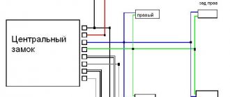
Connecting the signaling to the central locking system
Now we get to the most interesting part. The contacts of the signaling relay must be connected to the gap in the brown wire (see diagram in Chapter 1). Moreover, this will be required regardless of the configuration. Oddly enough, we won’t need power cables at all. And the task now looks like this: you need a two-wire signal cable connected to the break in the brown cord.
The moral here is:
- If you were able to remove the central lock control unit, connect the cable to the break in the wire connected to pin “7” of the control unit;
- If you have removed the door trim, then pull the cable out of it (from the point where the brown cord breaks).
It is clear that the second side of the cable must reach the relay connector of your alarm.
Option for the “Lux” package
So, this means that there is a button on the armrest in the cabin that allows you to lock the locks. From one of the contacts of the button, to which a “plus” is applied when pressed, you need to stretch the cord to the signaling unit. Nothing else is required, and you can connect the alarm according to the following scheme:
According to reviews, this option is suitable if we are talking specifically about the “luxury” configuration. By the way, the resistor can be connected to the gap in the wire designated “blue” (the common contacts are then connected with a jumper).
It must be remembered that when working with any electrical equipment, you must first remove the negative terminal from the battery.
Each cord that is re-laid must not touch metal surfaces. Otherwise, in places of contact, the wire is protected with a tube that can withstand temperatures of 250 degrees. This is how you can protect yourself from unforeseen consequences.
Option for the “Norma” configuration
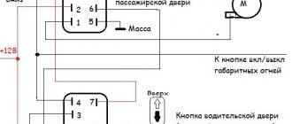
Let's say there is no button in the cabin that allows you to perform emergency closing. Then you need to connect the signaling to the central locking system according to the following scheme:
As you can see, unlike the first option, there are no resistors here, and positive voltage is not used at all. But in the luxury configuration the effect that is characteristic of this scheme will not be observed:
- We perform closing from the key fob - all locks are locked;
- We try to open the locks with the key fob - only the driver's lock unlocks.
If you are satisfied with this property, try to implement the scheme in practice. And other options, more advanced, look much more complicated.
Read what is said about installation safety in the previous chapter. Do not neglect the advice about disconnecting the negative terminal. We work only with signal circuits, so nothing will fail even if connected incorrectly. However, be careful not to confuse the locking and unlocking relays, which are located in the alarm unit. This unit is usually equipped with a 6-pin connector (for details, see the signaling manufacturer's instructions).
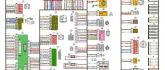
Pinout of lock VAZ-2113, VAZ-2114, VAZ-2115
Pinout of the ignition switch VAZ-2113, 2114, 2115:
- comes +12V for the microphone of the sensor of the inserted key;
- the mass comes when the driver's door is open;
- +12V goes to the starter (pin 50);
- +12V goes out after turning on the ignition (pin 15);
- +12V goes out when the key is inserted to pin 5 of the BSK;
- comes +12V to illuminate the lock cylinder;
- +12V comes from the battery (pin 30);
- not used.