There are quite a few different types of mass air flow sensors: mechanical, ultrasonic, hot-wire and some others.
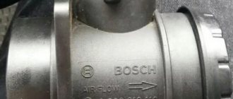
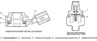
In this case, we will consider the design of the HFM-5 hot-wire sensor from Bosch, which is most often installed on VAZ cars. The sensor's sensitive element is a thin film on which several temperature sensors and a heating resistor are located. In the middle of the film there is a heating area, the degree of heating of which is controlled using a temperature sensor.
On the surface of the film, on the side of the air flow and on the opposite side, two more thermal sensors are located symmetrically, which record the same temperature in the absence of air flow. In the presence of air flow, the first sensor is cooled, and the temperature of the second remains unchanged, due to the heating of the air flow in the heater zone. The differential signal of both sensors is proportional to the mass of passing air.
- 1 – dielectric diaphragm
- H – heating resistor
- SH – Load temperature sensor. resistor
- SL – Air temperature sensor
- S1 and S2 – temperature sensors before and after the heater.
- QLM – air flow mass
- t – temperature
The sensor's electronic circuit converts this signal into a constant voltage proportional to the air mass. This design is called Hot Film (HFM), its advantages include high measurement accuracy and the ability to record reverse air flow, but its disadvantages include low reliability in conditions of contamination and moisture.
To measure the amount of air that enters the engine means to determine the engine load. When the driver presses the gas pedal, the throttle valve opens and the amount of intake air increases. At the same time, we say that the load has increased. When you release the pedal, the load drops. It's quite simple. However, this is only at first glance. If we take into account the fact that in real driving conditions the engine often changes operating modes and the incoming air in the intake system participates in several gas-dynamic processes, then the problem of measuring the air in the system is not so simple.
In older systems (ECU January-4 and GM-ISFI-2S), other hot-wire mass flow sensors were used, the sensitive elements of which were made in the form of threads. Such sensors are called Hot Wire MAF Sensor. The output signal of these sensors was frequency, that is, depending on the air flow, it was not the voltage that changed, but the frequency of the output pulses. The sensors were less accurate and did not allow registering reverse flow, but these shortcomings were offset by very high reliability.
Several types of mass air flow sensors were installed on VAZ cars: GM, BOSCH, SIEMENS and Russian-made. In 1999-2004 Two types of sensors were installed on VAZ cars: 0 280 218-037 and 0 280 218-004. These sensors produce different output voltage (calibration) parameters at the same air flow rate and interchangeability (or rather, replacing 004 with 037) is only possible with the replacement of calibration tables in the firmware. The same applies to the new sensor 116, which has been installed as standard since the beginning of 2005.
The sensor is supplied only assembled, with a code and marked with a green circle.
On some classic cars, together with the January 7.2 ECU, Siemens-VDO sensors (5WK97014. AVTEL) were used:
They differ in calibration (from zero volts) and connection diagram.
Checking the serviceability of the mass air flow sensor with a multimeter
You can also check the air flow in the VAZ-2110 using a multimeter.
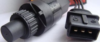
This method is well suited if the car has a Bosch sensor with numbers 0280218004, 0280218037, 0280218116. Each cable in the VAZ-2110 sensor device provides separate functions:
- yellow – indicates the signal input to the installation;
- gray-white – removes supply voltage from the mechanism;
- green – determines the grounding output;
- pink with black - approaches the main relay.
Note that the wire colors may change, but the pinouts remain the same. For a better understanding of the mass air flow sensor in the VAZ-2110, a diagram of the sensor is presented below.
Step-by-step instructions for checking the mass air flow sensor in a VAZ-2110 with a multimeter look like this:
- Turn on the ignition, but do not start the engine.
- Connect the multimeter with the red wire to the yellow, black to green, using a probe. This procedure allows you to determine the voltage that has arisen between the terminals.
- What’s good about the probe is that it is inserted through rubber seals along the wires without violating the integrity of the insulating material. The use of needles is considered incorrect; the error in measurements may be large.
- Next, take readings from the multimeter.
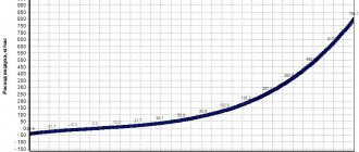
The output voltage of the new device varies from 0.996 to 1.01 Volts. During operation, the values may change, mostly increasing. A higher voltage indicator indicates a greater degree of wear on the mass air flow sensor:
- from 1.01 to 1.02 – the sensor is fully operational;
- from 1.02 to 1.03 – the condition is not bad;
- from 1.04 to 1.04 - soon the air meter will have to be changed;
- from 1.04 to 1.05 – the condition is critical, operation is possible if no negative symptoms are reported;
- more than 1.05 – it’s time to replace the sensor on the VAZ-2110 immediately.
How to deceive the mass air flow sensor using ECU firmware
The good thing about the previous method is that its implementation does not require complex equipment or painstaking work. If you were able to check the voltage at the output of the flow meter with a multimeter (which means you at least have one), and know how to hold a soldering iron in your hands, installing a resistor in the wire gap will not be difficult. However, the dependence of voltage on air flow mass is nonlinear. And when the throttle valve opens, the error of the signal corrected by the resistor at rest will increase. Accordingly, the fuel-air mixture will not be ideal.
This means that you need to adjust the MAF calibration in the ECU firmware.
Attention! If you do not have experience working with car software, it is better to entrust this operation to professionals.
- We install the specialized tuning program “DFID Corrector” on the laptop.
- We connect the car scanner to the OBD-II connector and establish communication between the ECU and the computer.
Important! During operations with the ECU controller firmware, the 12 volt power supply should not be lost. Therefore, you need to make sure that the battery is fully charged.
- We adjust the voltage of the MAF ADC at rest (air mass 0 kg/hour) to the required 1 V.
- Save the firmware changes.
After calibration, the data on mass air flow will be correct throughout the entire engine speed range.
Attention: After you install a new flow meter, you must return the calibration to the factory (standard) state.
This is interesting: What gap should be on the Hyundai Solaris on the spark plugs
Cleaning the sensor
Oxygen sensor on a 16-valve VAZ-2112 engine: signs of a malfunction
In some cases, it is possible not to flush the VAZ 2110 DMV, but to replace it. But many people don’t know how to clean the DMV VAZ.
These procedures are easy to do yourself:
- first you need to disconnect the pipe from the mass air flow sensor;
- then the sensor itself is removed, this is necessary for better flushing of the DMV VAZ2110;
- to remove the sensor, use a special key with asterisks;
- unscrew the fastening systems and remove the sensor from the pipe and inspect its appearance;
- in some cases, an oil deposit forms on the sensor, but after cleaning the sensor will be as good as new;
- to clean the sensor you need to purchase a special carburetor cleaner;
- There is a film inside the sensor, and there are thin wires on it, and in order not to damage them, you should carefully spray them with the product;
- leave for a while to allow the sensor to dry; it is best to use the product in cans;
- Some people use alcohol to clean the sensor; it will also clean it well;
- Also, when cleaning the sensor, do not forget about cleaning the pipe from accumulated dirt and dust;
- After cleaning, allow the parts to dry and then reassemble in the reverse order.
And after such measures are taken, the sensor can function and continue to work. But in some cases it is still worth replacing the sensor.
There are several price categories for the mass air flow sensor:
- Low cost, most often these are Chinese-made parts, and their cost does not exceed 1000 rubles, but experts do not recommend purchasing cheap sensor options.
- Average cost, most often these are AvtoVAZ parts, which can be of domestic or foreign production, their cost ranges from 1500-2500 rubles.
- It is best to purchase more expensive sensors, they are of high quality and reliable, but the cost here can be higher than 5,500 rubles, and they have a long service life.
When choosing, you should pay attention not only to the cost of the sensor, but you also need to take into account the manufacturer, and it is better to choose foreign manufacturers. They are usually of average cost and good quality
How to restore the mass air flow sensor?
Signs of a faulty air sensor on a VAZ, Niva Chevrolet and foreign cars; auto innovator
The optimal solution for problems with the mass air flow sensor is to replace the faulty sensor with a new one. But since the cost of the device is about 2500-3900 rubles, many owners are trying to “revive” the old part.
There are four recovery methods:
- installation of additional resistance;
- blocking part of the air supply channel to the thermistor with aluminum tape;
- updating the engine control unit firmware;
- washing the sensor body and housing from dirt.
Installing additional resistance
Additional resistances are installed in the circuit connecting the sensor to the control unit. When an electric current passes, the voltage decreases, which can be brought to the required limits. The resistance value is selected experimentally. Most often, a 1 kOhm resistor is soldered to the yellow wire and a 15 kOhm element to the green wire.
Blocking part of the air supply channel
The repair principle is based on partially cutting off the air supply to the thermistor. Due to this, less intensive cooling is ensured and it is possible to bring the voltage value to the state of a working device. The cross section is selected experimentally with voltage monitoring using a multimeter. In some cases, owners block the supply channel by 70-80%. Aluminum tape is used for gluing.
Correcting the firmware of the engine control unit
An adjustment means a change in the calibration or operating schedule of the mass air flow sensor stored in the unit’s memory. The dependence graph is constructed in such a way that at a sensor voltage of 0.996 volts, the flow rate is considered equal to zero. But if the sensor fails and the starting voltage is 1.055 volts, then the control unit considers the air supply to be 1.8 kg when the engine is not running. Changing the graph using the MAF Corrector utility will allow you to set the flow rate to 0, which will improve engine performance. This method can be recommended to owners who are well versed in the control unit software.
Do-it-yourself cleaning of the air flow sensor
The air volume sensor is cleaned after it is detected that it is not working correctly. The procedure is performed by partially disassembling and removing the device body with active elements. At the same time, the body is washed and cleaned from remaining leaves and dirt deposits. In many cases, washing the air flow sensor on a VAZ 2114 does not help restore the device’s parameters.
Mechanical methods 2114 are prohibited, as is blowing dust with compressed air.
What products should be used to clean the sensor?
To clean sensors, there are special liquids supplied in pressurized aerosol cans. An example of such a product is a special air flow sensor cleaner Luftmassensor-Reiniger from Liqui Moly. There are similar liquids from other manufacturers. You can wash the sensor with a mixture of 70% isopropyl alcohol and 30% distilled water, after warming the device to 60-70 ºС with a hair dryer.
When washing the mass flow sensor it is prohibited:
- try to clean the sensor with cotton balls, hard objects and brushes;
- use household cleaning products;
- Use carburetor cleaners based on acetone or ether.
Cleaners based on heavy petroleum products, for example, WD40, will remove plaque from working parts, but will leave a greasy film that must be washed off with isopropyl alcohol. The use of ether-containing substances is not recommended due to the destruction of the compound filling and electronic components.
Algorithm of actions
Sequence of steps when washing the mass air flow sensor:
- Remove the sensor together with the housing from the engine air duct. The device is attached with a clamp to the channel and two bolts to the air filter housing.
- Unscrew the two screws securing the sensor to the housing. The bolts have a star head, but many owners unscrew them with pliers.
- Wash the measuring thermistors and the air passage channels with a cleaning agent. If the cleaning method with alcohol is used, the removed sensor is heated with a stream of warm air and placed in a container. The alcohol-water mixture is also heated to 60-70 degrees.
- Dry the sensor.
- Wash the sensor housing with warm soapy water. Rinse under running water and dry.
- Assemble the sensor and install it in place.
Design and purpose of the air flow sensor VAZ 2107
The electronic engine control unit receives information about the amount of air entering the combustion chambers of the cylinders. Based on these data, the dosage of gasoline intake is calculated to form the optimal composition of the air-fuel mixture. DMRV VAZ 2107 (injector) is installed between the air filter and the throttle valve. The speed of air flow passing through the sensor is measured by monitoring the temperature of the electrical conductors. The sensor contains two conductive platinum threads. One is blown by passing air, the second serves for control. The passing air cools the first conductor and its resistance decreases. The degree of cooling, and, consequently, the amount of air passed, can be determined by the difference in resistance of the two threads: the larger the volume of air passes, the more the conductor is cooled and the more its resistance decreases. Specific calculations are made by the on-board computer based on algorithms that take into account not only the difference in the resistance of the threads, but also the current temperature of the control conductor.
How to replace the air flow sensor on a VAZ 2110
Crankshaft sensor for VAZ 2112 16 valves
Replacing the sensor yourself is not difficult. After the operation of the device has been checked and if there is no point in cleaning the sensor, you can begin to replace it.
- The car is placed on a flat surface, and the negative terminal must be removed from the battery.
- Then the sensor is turned off.
- To remove the clamping bolt of the clamp, use a screwdriver; it is located on the corrugation.
- We remove the corrugation.
- Then unscrew the bolts on the air filter.
- Now you can remove the old sensor and install a new one in its place.
- You can reassemble in reverse order.
If all the work is carried out correctly, the car will again regain power and dynamics, and the sign on the instrument panel will disappear. To check the correct operation of the MAF sensor, you should drive the car. If everything returned as it was before the breakdown, then the repair was carried out correctly, and the cause was the DMVR sensor.
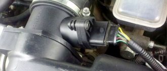
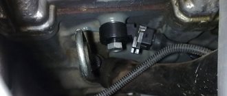
Where is the DMRV located?
The sensor is located between the air filter and the air supply hose (pictured No. 13).
Catalog numbers of mass air flow sensor on LADA cars:
- Lada Priora, Kalina and Niva 4x4 - 21083-1130010-20.
- Lada Granta and Kalina 2 - 11180-1130010-00.
- Lada Vesta, Largus and XRAY - no mass air flow sensor. Modern VAZ engines (21127, 21129, 21179) and Renault engines (K7M and K4M) do not have a mass air flow sensor; instead, an absolute pressure sensor (APS) and an air temperature sensor (ATS) are installed.
Cleaning the sensor
If you observe signs of a malfunction of the mass air flow sensor, then you can try cleaning the device.
By the way, this is the most expensive sensor of all in the line of front-wheel drive VAZ cars. But if yours is broken, don’t rush to change it. There is a small chance of restoring his “health”.
For the cleaning process you will need a special liquid that is used to clean the carburetor. Star keys are also useful. Unscrew the clamp, as well as the two “10” bolts.
Remove the pipe and take out the sensor. Spray the liquid onto the wire and tube. Work with extreme care, wait until this liquid has completely evaporated and leave the device to dry.
While the device is drying, remove the throttle assembly. You will see plaque inside the throttle assembly. It needs to be removed with liquid.
This dirt causes problems with the entire system. Because of it, problems with the mass air flow sensor appear, signs of a malfunction of the VAZ 2115, which bother beginners on automobile forums.
Do not remove the throttle cable. Place the knot on a cloth and treat particularly dirty areas with the liquid. Don't forget to clean the idle air control valve and the space underneath it.
After this, most likely, all signs of problems with the mass air flow sensor will go away, of course, provided that the sensor has no mechanical damage. Therefore, do not wait until you have the first signs of such problems, but take such prevention this coming weekend. It won't take you much time, and your car will truly breathe.
You won't recognize your engine. It will start much better, its traction will improve, and you will notice an increase in the power of your engine.
Carry out such preventive maintenance regularly, and your car will thank you.
The automotive market does not stand still; manufacturers are constantly improving car engine power, fuel consumption, aerodynamic values, and coming up with options for changing overall comfort. The main and obvious improvement was the transition from the use of a carburetor method of power supply to a more efficient injection system.
How does the latter work? Regulates the quantitative supply of fuel according to a single dosage for the operation of the power plant in different formats of activity. This allows you to reduce the amount of air consumption and ensure maximum power output from the power structure.
However, mechanics argue that the design of the carburetor system is technologically simpler, because the carburetor operates mechanically, which means that the mechanism can be assumed to be highly reliable. The VAZ-2110 is equipped with such a system. The advantage of the device is that the fuel-air mass is formed in the carburetor and in the cylinders through vacuum, which is created by the pistons.
- how is the crankshaft positioned?
- what is the rotation speed;
- how much air enters the cylinders;
- what volume is contained in the exhaust gas;
- where is the throttle valve located.
These data and the calculation of the required fuel are responsible for the sensors recorded in the individual components of the power product - mass air flow sensor, which we will look at in more detail right now.
Types of mass air flow sensors, their design features and operating principle
Three types of VU meters are most widespread:
- Wire or thread.
- Film.
- Volumetric.
In the first two, the operating principle is based on obtaining information about the mass of the air flow by measuring its temperature. The latter may involve two accounting options:
- By changing the position of the slider, driven by a special blade, which is affected by the air flow passing through the device. Considering the presence of rubbing mechanisms, the level of reliability of such structures is quite low. This was the main reason for the refusal of car manufacturers from sensors of this type. For reference, here is a simplified example of the design of a volumetric flow meter.
Volumetric air flow sensor device - By counting Karman vortices. They are formed if a laminar air flow washes over an obstacle whose edges are quite sharp. The frequency of the vortices breaking off from them is directly related to the speed of air flow passing through the device.
Vortex sensor design (widely used by Mitsubishi Motors)
Designations:
- A – pressure measurement sensor to record the passage of the vortex. That is, the frequency of pressure and vortex formation will be the same, which makes it possible to measure the flow of the air mixture. At the output, using an ADC, the analog signal is converted to digital and transmitted to the ECU.
- B - special tubes that form an air flow similar in properties to laminar.
- C – bypass air ducts.
- D – column with sharp edges on which Karman vortices are formed.
- E – holes used to measure pressure.
- F – direction of air flow.
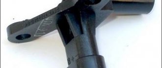
Wire sensors
Until recently, thread mass air flow sensor was the most common type of sensor installed on domestic cars of the GAZ and VAZ model range. An example of a wire flow meter design is shown below.
Design of volumetric meter IVKSH 407282.000
Designations:
- A – Electronic board.
- B – Connector for connecting the mass air flow sensor to the computer.
- C – CO adjustment.
- D – Flow meter housing.
- E – Ring.
- F – Platinum wire.
- G – Resistor for temperature compensation.
- N – Ring holder.
- I – Electronic board casing.
Operating principle and example of a functional diagram of a filament VU meter.
Having understood the design of the device, let's move on to the principle of its operation, it is based on the hot-wire method, in which a thermistor (RT), heated by the current passing through it, is placed in the air flow. Under its influence, the heat transfer changes, and, accordingly, the resistance RT, which makes it possible to calculate the volumetric flow rate of the air mixture? using King's equation:
where I is the current passing through RT and heating it to temperature T1. In this case, T2 is the ambient temperature, and K1 and K2 are constant coefficients.
Based on the above formula, you can derive the volumetric air flow rate:
An example of a functional diagram with bridge connection of thermoelements is shown below.
Typical functional diagram of a wire mass air flow sensor
Designations:
- Q - measured air flow.
- U – signal amplifier.
- RT - thermal resistance wire, usually made of platinum or tungsten filament, the thickness of which is in the range of 5.0-20.0 microns.
- RR – temperature compensator.
- R1-R3 are ordinary resistances.
When the flow velocity is close to zero, the RT is heated to a certain temperature by the current passing through it, which allows the bridge to be kept in equilibrium. As soon as the flow of the air mixture increases, the thermistor begins to cool, which leads to a change in its internal resistance, and, as a result, an imbalance in the bridge circuit. As a result of this process, a current is generated at the output of the amplifier unit, which partially passes through the temperature compensator, which leads to the release of heat and makes it possible to compensate for its loss from the flow of the air mixture and restores the balance of the bridge.
The described process allows you to calculate the flow rate of the air mixture based on the amount of current passing through the bridge. In order for the signal to be perceived by the ECU, it is converted into a digital or analog format. The first allows you to determine the flow rate by the frequency of the output voltage, the second - by its level.
This implementation has a significant drawback - a high temperature error, so many manufacturers add a thermistor similar to the main one to the design, but do not expose it to air flow.
During operation, dust or dirt deposits may accumulate on the wire thermistor; to prevent this, this element is subjected to short-term high-temperature heating. It is performed after the internal combustion engine is turned off.
Symptoms of a faulty air flow sensor
If the mass air flow sensor begins to produce incorrect data, then a failure occurs in the system for preparing the fuel-air mixture, and the proportions of fuel and air are disrupted. This results in the following symptoms of a malfunction:
- Unstable idle speed
- Violation of the smooth running of the car
- Difficulty or impossible to start the engine
- Noticeable deterioration in vehicle dynamics
- Increased fuel consumption
- The yellow "Check Engine" light on the instrument panel does not go out
Check engine light on the instrument panel
If the Check Engine light is constantly on on the instrument panel, the easiest way to check, if you have a diagnostic tool, is to read the error codes, which will allow you to pinpoint the problem. One of the most common DMRV errors is error p0100. Explanations of diagnostic codes can be found in the technical literature for a specific vehicle.
None of the above symptoms are a 100% guarantee that the mass air flow sensor has failed. Other vehicle systems may also be to blame. But all these symptoms together, or each one separately, give reason to check the flow meter for performance.
Checking the air flow meter
One way to check the air flow sensor
There are several ways to detect a malfunction of this sensor. The easiest way is to disconnect the power supply from the sensor while the engine is running. After the chip is turned off, the control unit goes into emergency mode, in which fuel dosage is carried out according to the readings of the throttle position sensor. In this case, the idle speed will begin to increase to over 1500 revolutions, although not always; some injection systems do not increase the speed.
With the flow meter turned off, you need to drive the car. If the performance of the power plant has improved, most likely there are problems with the mass air flow sensor.
Video: Demonstration of a faulty mass air flow sensor on Kalina, Priora, Grant, VAZ 2110-2112, 2114-2115
Some sensors can be checked using a voltmeter or multimeter with high precision settings. The measuring device is connected with a “positive” probe to the MAF signal wire (usually the far right wire), and with a “negative” probe - to the ground wire of the sensor. Then you need to turn on the ignition, but do not start the power plant. A working sensor should have a voltage between 0.9 and 1.4 V. The readings above indicate a sensor malfunction.
Very often the failure is caused by contamination of the working elements of the sensor. Therefore, a visual inspection can also indicate a malfunction.
If the working elements of the sensor are noticeably heavily soiled, this is most likely the cause of problems with the operation of the power plant. But restoration work can be done with sensors based on a pitot tube. They can be removed from dirt by washing with a carburetor cleaning spray.
Principle of operation
The piston stroke occurs when fuel is burned with air in a ratio of 1:14, maintaining which ensures optimal operation of the power plant. When the proportion decreases or increases, the engine does not stop working, but there is excessive fuel consumption or a decrease in engine operating power. We need a mass air flow sensor so that air flows in portions. The operation of the unit proceeds as follows: the VAZ 2110 air flow sensor calculates the portion of fresh air, and then sends the data to the main computer, which, based on this information, calculates the portion of fuel.
The harder you push the gas, the more filtered air the powerplant requires. The mass flow sensor detects the increase and commands the electronics to increase the amount of fuel. When moving at the same speed, each portion should be equal to the previous one. The mass air flow sensor receives data on the load of the power unit, and then calculates the required portion of air. When the driver presses the pedal, the throttle valve opens, thereby increasing the volume of intake air - the load increases. When the pedal is released, the load drops.
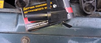
When you need to change the DFID sensor 2110: symptoms of sensor malfunction and check
During the operation of a vehicle, the mass air flow sensor 2110 can fail for various reasons, one of which is the long period of use of the device. When a sensor fails, it is usually not repaired; it is simply replaced with a new one. The following symptoms may indicate that the sensor is not working properly:
- “Check Engine” lights up on the car’s dashboard (you need to check the engine);
- fuel consumption increased, acceleration dynamics decreased;
- the car engine does not start;
- at idle, the car’s internal combustion engine operates jerkily (change in idle speed down or up).
All of the listed signs of sensor malfunction indicate that air is not being supplied to the mixture in the volume required. Taking into account the fact that this problem may be associated not only with a malfunction of the mass air flow sensor, before proceeding with dismantling the sensor, it is necessary to make sure that it is faulty.
In fact, the VAZ 2110 mass air flow sensor can be checked for performance using three methods: in motion, with a multimeter, visually. Checking the mass air flow sensor 2110 experimentally (in motion) is the easiest and fastest way. It consists of analyzing the operation of the vehicle’s internal combustion engine when the sensor is forcibly turned off.
Algorithm of actions:
opening the hood, disconnect the mass air flow sensor connector; start the car engine; since the car will operate in emergency mode, the “Check Engine” light will come on and the amount of air in the fuel mixture will be determined depending on the throttle position; Having driven a car operating in emergency mode, you need to pay attention to its dynamics and compare them with the dynamics before the sensor was turned off; If the car accelerates faster with the sensor turned off, the air flow sensor is faulty.
The next stage of diagnosis may be checking the mass air flow sensor 2110 with a multimeter. This method of checking the sensor for functionality involves the use of a measuring device (multimeter).
Before checking, you need to understand the design of the device and find out its “pinout” (soldering of wires on the board). There are four wires coming out of the MAF. Typically these are the wire to the main relay (pink/black or pink), ground (green), power (gray), and signal input (yellow).
To check you need:
- set the multimeter to constant voltage measurement mode, setting the limit to 2 Volts;
- without starting the engine, turn on the ignition;
- connect the black multimeter probe to the ground wire, the red one to the signal input of the multimeter sensor, inserting the multimeter probes through the rubber seal of the connector;
- take measurements and use the results to determine the state of the sensor.
Based on multimeter readings:
- voltage 0.996-1.01 Volts (new sensor);
- voltage 1.01-1.02 Volts (working sensor in good condition);
- voltage 1.02-1.03 Volts (sensor working, with long-term operation);
- voltage 1.03-1.05 Volts (sensor is worn out and may fail);
- voltage from 1.05 Volts and above (the sensor is faulty and requires replacement).
If the device is not at hand, the faulty sensor can often be determined by its appearance, that is, by visual inspection. In this case, it is necessary to dismantle the device and carefully inspect it for mechanical damage or for the presence of liquid in the sensor and air pipe.
The reasons for liquid and dirt getting into the sensor can be different (for example, the oil level in the crankcase is increased, dust gets on the hot-wire anemometer due to untimely replacement of the air filter, the oil sump of the crankcase ventilation system is clogged, etc.).
Testing and diagnostic methods
Shutdown
This method involves starting the motor with the sensor removed - we need to disconnect its connector. When turned off, the controller starts emergency mode, and new portions of the mixture are calculated based on the position of the damper. We need to drive a little, the speed should be above 1500 rpm. If the car behaves more dynamically without a mass air flow sensor, then the diagnosis is complete - it’s time to change the consumable.
Checking with a multimeter
This test requires that you have skills in using a multimeter (tester). The method is suitable for almost all VAZ models, including 2110. We need to take a multimeter and set it to a mode that measures constant voltage, which is usually designated DCV or only V. To work with the mass air flow sensor, you need to understand its pinout, it is as follows:
- Yellow, closest to the windshield, supplies current to the signal input;
- Green indicates ground;
- The pink or red-black wire comes from the main relay;
- The white-gray wire is responsible for the voltage output.
Depending on the model, the colors may be different, but the location does not change. Here you will have to deal with a specific model. But once you find the input signal wiring (closer to the windshield) and grounding, you can do it without instructions. The wiring is clear, now you need to turn on the ignition without starting the engine. The tester sets a limit of 2 Volts. The black probe of the tester is connected to the green ground wire of the air flow sensor, and the red one is connected to the yellow one. The measurement takes place between two terminals
The probes must be inserted carefully; an additional needle is not required, since the probes can be freely inserted along the wires without damaging the insulation
We look at the tester display. If the consumable is new, then there we will see a voltage indicator of 1.01. Over time, the indicator increases as the resistors wear out (the resistance drops). The larger the number, the greater the wear of the sensitive element:
- In good condition, the indicator will be 1.01… 1.02;
- With “normal” - 1.02... 1.03;
- The sensor will soon stop working – 1.03… 1.04;
- The dying state of the flow meter is accompanied by an indicator of 1.04… 1.05;
- Replacement of the unit is required when the reading is 1.05 or higher.
Diagnostics can also be carried out without a multimeter. Instead, you can use the on-board computer. To do this, you need to go to the “voltage from the mass flow sensor” section; we are interested in the “U MAF” indicator.
Visual inspection
Here we need to carefully examine the surface of the corrugation and consumables. To check the condition, we need to loosen the air intake clamp at the outlet of the mass air flow sensor, and then pull it off. If you see traces of grease or condensation on the surface, then most likely they have damaged the unit. Sometimes the sensor can be “reanimated” by removing all the dirt. It ends up in the consumables due to rare changes of the air filter. If liquid appears on the sensitive element, this is a 90% failure. Lubricating oil enters due to a clogged oil separator or due to an increased level in the crankcase.
If the above-described elements are detected, the diagnosis can be completed. If the surface is clean, move on. Remove the consumable from the air filter. It is held in place only by 2 screws, which are unscrewed with the 10th key. Looking at the photo, we see that there is an o-ring on the front of the mass flow sensor. It is installed for sealing - unfiltered air cannot leak through the inlet.
If this ring (in the photo it is green, but your color may be different) has slipped or remains in the filter housing, then a layer of dust can be found on the consumable mesh. Such a defect is enough to cause the sensitive element to fail. You need to assemble the unit according to the following scheme: check the reliability of the sealing skirt, put on the rubber ring, place the sensor in the air filter housing.
System depressurization
If depressurization occurs in the intake tract system, then instability in engine operation occurs. Air leaks occur in the following parts of the car:
- In sealed areas of the nozzle;
- On exhaust systems for gasoline vapors;
- On the walls of the throttle frame;
- On idle jets;
- On the vacuum brake booster pipes;
- On the cleaning pipes.
Due to improper air removal, improper mixing of fuel masses occurs. Emergency symptoms are detected during the operation of the intake tract. The air leaving the system does not pass through the filtration system. It contains many harmful particles of dirt, metal, and plastic, which enter the engine and threaten to lead to poor performance of the latter.
What is the difference between sensors 037 and 116?
How can the regulators of these models differ from each other and is it possible to install 116 instead of 037? There are differences between these controllers, and the point is not in the MAF pinout. After all, if these models were the same, what would be the point of giving them different names?
So, how do the controllers differ from each other and is it possible to install model 116 instead of 037:
- The first difference that can be guessed based on the technical characteristics is that the 037 model can produce data with an error during operation. Of course, an error of 2.5% is not critical, but it does exist.
- Device 037 is intended for installation in VAZ 2111, 2112, 2123, 21214 cars, which are equipped with controllers M 1.5.4, January 5.1-5.1.3, etc.
- As for model 116, its use is relevant on Ladas 21114, 21124, 21214. Installation of this device is allowed on Kalina and Priora. Installation of the device is allowed on cars equipped with M 7.9.7 and January 7.2 controllers.
If you encounter a problem with the device not working, then when replacing it you need to install the same model that has already been installed. But it is worth considering that 037 is not a common option like 116, so it is more difficult to find. The latter, in turn, is more common, and its cost is lower.
Replacement is allowed, but experts do not recommend this. This is because these devices differ in their calibration, so in case of replacement, you will have to change the parameters of the control unit. And you can only get into the “brains” of a car if you understand what needs to be done and have minimal experience.
Loading …
Signs of a malfunction of the mass air flow sensor on a VAZ 2110: how to rinse and clean it yourself
When the first signs of a malfunction occur, you should definitely check the mass air flow sensor, and then, depending on the situation, clean or replace the device.
Now let's talk about how to check our sensor. Today, two main methods of checking the mass air flow sensor are used.
- The engine is tested in operation with the mass air flow sensor disconnected. Simply turn off the power from the regulator and start the motor. When the mass air flow sensor is not present during startup, the electronic control unit turns on the power unit in emergency mode. The speed is adjusted to 1500 rpm. After disconnecting the sensor, drive a few kilometers and evaluate the dynamics and power. If the engine is running normally, then the sensor is the cause of the symptoms.
- The second method will require the use of a car tester or voltmeter. After starting the ignition, do not start the engine. The voltage threshold is set on the tester to 2V. The positive probe connects to the yellow wire on the sensor connector, and the black probe connects to the green wire. Next, refer to the table.
Index
Air flow sensor condition
The sensor is functioning normally
Not ideal, but still acceptable voltage readings
Maximum permissible values that indicate imminent sensor failure
The air flow sensor has failed and needs to be replaced
Quite often you can avoid replacing the mass air flow sensor by simply cleaning this engine element.
You should do the cleaning yourself in this way:
- Remove the pipe from the mass air flow sensor;
- Now remove the sensor from the pipe. Otherwise, high-quality washing will not work;
- To remove the sensor, arm yourself with sprocket keys in advance. Finding such kits is not a problem;
- Unscrew all the fasteners, remove the sensor from the pipe and assess its external condition;
- Often there are traces of oil deposits on the sensor. The purpose of cleaning is to make the device as good as new;
- Carburetor cleaner is often used to clean the air flow sensor;
- Inside the film there are sensors, which are small wires attached to a special resin. These elements must be carefully sprayed with cleaner so as not to damage the devices;
- Wait a while for the surfaces to dry. To speed up the process, use a can of compressed air;
- It is not uncommon to use alcohol instead of carburetor cleaner, which also works quite effectively;
- Proper cleaning of the mass air flow sensor involves treating the pipes from accumulated debris, dirt and dust;
- Having carefully processed all the components of the removed mass air flow sensor, wait until it dries, and then reassemble it. Cleaning is complete.
Spray cleaning
Statistics show that in about 80% of cases, simple cleaning can return the mass air flow sensor to its previous functionality.
Price issue
80% is not 100. Therefore, sometimes you have to change the sensor. And to replace it, you need to buy it.
There are three price categories for air mass flow sensors:
- Cheap. These are predominantly Chinese products, the price of which is up to 1000 rubles. It is strongly not recommended to purchase such regulators;
- Average. These include sensors from AvtoVAZ, domestic and some foreign analogues. These cost from 1500 to 2500 rubles;
- Expensive. High-quality, reliable, imported air flow sensors, the price of which can reach 5.5 thousand rubles. It’s hard to say how rational it is to buy them. But they will definitely last a long time.
It is not difficult to replace the mass air flow sensor with your own hands, even if you do not have any special skills in car repair. Having checked the condition of the device and determined that cleaning will not help, all that remains is to replace it.
- Place the car on a level surface, lift the hood and remove the negative terminal from the battery.
- Disconnect the sensor connector. We have already talked about its location, so there will be no problems with the search.
- Using a screwdriver, remove the clamping bolt of the clamp that secures the corrugation to the mass air flow sensor.
- The corrugation is removed.
- Using a 10mm wrench, unscrew the two bolts that hold the sensor to the air filter housing.
- After removing the failed oxygen sensor, install a new regulator in its place.
- Screw back a couple of bolts, secure the corrugation and secure it with a clamp.
- Reconnect the connector and return the negative terminal to the battery.
If everything is done correctly and the breakdown is correctly identified, then the engine will return to its previous performance and the error signal on the dashboard will disappear.
Replacing the device
To finally check the result of the repair, go out onto the road, do a test drive and be sure to try to press the gas pedal sharply. If the dynamics and power become the same as before the problems arose, you did everything correctly, and it was the mass air flow sensor that was the culprit of the malfunction.
How to check the DMRV on a VAZ 2110
Disconnect the sensor connector. Start the engine. Increase engine speed to 1500 rpm or more. Start moving. If you feel the car “swiftly”, this means that the mass air flow sensor is faulty and needs to be replaced with a new one. This is the first check option. If the mass air flow sensor is disabled, the controller goes into emergency mode, so the mixture is prepared only according to the throttle valve.
Turn the tester into DC voltage measurement mode, set the measurement limit to 2 V. The second option for checking the mass air flow sensor. Measure the voltage between the yellow “output” wire (closest to the windshield) and the green “ground” wire (3rd from the same edge), located in the sensor connector. Colors may vary depending on the year of production, but the layout remains the same. Turn on the ignition, but do not start the engine. Use the tester's probes to penetrate through the rubber seals of the connector, along these wires, and reach the contacts themselves without breaking the insulation. Connect the tester and take readings. These parameters can also be removed from the on-board computer display, if available. They are in the group of “voltage from sensors” values and are designated U dmrv.
Evaluate the results. At the output of a working sensor, the voltage should be 0.996-1.01 V. During operation, it gradually changes upward. Using this parameter, you can determine the degree of “wear” of the sensor. For example: 1.01-1.02 V – the sensor is working, 1.02-1.03 V – the sensor is working, but is already “planted”, 1.03-1.04 V – it will soon need to be replaced, 1.04-1.05 V – it’s time to change it, 1.05 V and above – operation is impossible, mandatory replacement.
Inspect the sensor when readings are abnormal. Take a shaped screwdriver and unscrew the clamp of the rubber corrugation of the air inlet, which is located at its outlet. Remove the corrugation and carefully inspect its internal surfaces and the sensor. They should be free of condensation and oil. This is the most common cause of damage to the air flow sensor. If they are, it means the oil level in the crankcase is too high and the crankcase ventilation oil trap is clogged. Before replacing the sensor with a new one. The problem must be corrected.
ADC codes
ADC code parameters relate to analog sensors of the control system:
Physically, ADC codes reflect the voltage that the sensor produces. Typically, these parameters are used to test sensor circuits. If fault codes occur associated with a low or high signal level of such a sensor, then the control system operates in backup modes. In this case, the value of the parameter related to this sensor is selected either from the emergency table or calculated using specified formulas, for example, the coolant temperature with a faulty temperature sensor increases during engine operation.
If, during a physical change in the parameter measured by the sensor, the ADC code remains a constant value, then the electrical circuit connecting the sensor is inoperative.
ADC values are dimensionless, but for the user in scanner testers they are translated into the voltage that a particular sensor produces.
Therefore, using an ADC code, for example, from an L-probe sensor, you can more clearly evaluate the work in the feedback loop system to maintain the stoichiometric composition of the mixture. If the L-probe sensor is inoperative, then the ADC code is in the range of 0.4-0.7V.
The ADC code value (output voltage) from the throttle position sensor can indicate the lower limit at which the system detects sensor error. A throttle position equal to zero corresponds to a voltage from the sensor of 0.52 V.
When the ignition is on, the output voltage from the mass flow sensor (ADC code) should be 1.00V.
The temperature sensor, throttle position sensor, mass flow sensor are powered by a voltage of 5.00V, which is supplied by the control unit. If the control unit produces an unstable voltage, then the sensor readings will change and the behavior of the system in this case is unpredictable.
Features, diagnostics and replacement of elements of injection systems on VAZ cars
Below we will look at the main controllers!
Hall
There are several options for how you can check the Hall sensor of a VAZ:
- Use a known working device for diagnostics and install it instead of the standard one. If after replacement the problems in engine operation cease, this indicates a malfunction of the regulator.
- Using a tester, diagnose the controller voltage at its terminals. During normal operation of the device, the voltage should be from 0.4 to 11 volts.
The replacement procedure is performed as follows (the process is described using the example of model 2107):
- First, the switchgear is dismantled and its cover is unscrewed.
- Then the slider is dismantled; to do this, you need to pull it up a little.
- Remove the cover and unscrew the bolt that secures the plug.
- You will also need to unscrew the bolts that secure the controller plate. After this, the screws that secure the vacuum corrector are unscrewed.
- Next, the retaining ring is dismantled and the rod is removed along with the corrector itself.
- To disconnect the wires, you will need to move the clamps apart.
- The support plate is pulled out, after which several bolts are unscrewed and the manufacturer dismantles the controller. A new controller is being installed, assembly is carried out in the reverse order (the author of the video is Andrey Gryaznov).
Speeds
The following symptoms may indicate a failure of this regulator:
- at idle, the speed of the power unit floats, if the driver does not press on the gas, this can lead to an arbitrary shutdown of the engine;
- the speedometer needle readings float, the device may not work as a whole;
- fuel consumption has increased;
- the power of the power unit has decreased.
The controller itself is located on the gearbox. To replace it, you only need to jack up the wheel, disconnect the power wires and remove the regulator.
Fuel level
The VAZ or FLS fuel level sensor is used to indicate the remaining volume of gasoline in the fuel tank. Moreover, the fuel level sensor itself is installed in the same housing with the fuel pump. If it malfunctions, the readings on the dashboard may be inaccurate.
The replacement is done like this (using the example of model 2110):
- The battery is disconnected and the rear seat of the car is removed. Using a Phillips screwdriver, unscrew the bolts that secure the fuel pump hatch and remove the cover.
- After this, all wires leading to it are disconnected from the connector. It is also necessary to disconnect all the pipes that are supplied to the fuel pump.
- Then the nuts securing the clamping ring are unscrewed. If the nuts are rusty, treat them with WD-40 before unscrewing.
- Having done this, unscrew the bolts that directly secure the fuel level sensor itself. The guides are pulled out from the pump casing, and the fasteners need to be bent with a screwdriver.
- At the final stage, the cover is dismantled, after which you will be able to gain access to the FLS. The controller is replaced, the pump and other elements are assembled in the reverse order of removal.
Idle move
If the idle speed sensor on a VAZ fails, this is fraught with the following problems:
- floating speed, in particular, when additional voltage consumers are turned on - optics, heater, audio system, etc.;
- the engine will start to stall;
- when the central gear is activated, the engine may stall;
- in some cases, failure of the IAC can lead to body vibrations;
- the appearance of a Check indicator on the dashboard, but it does not light up in all cases.
Methods for checking sensor functionality
How to check the flow meter yourself? There are several diagnostic options, we suggest you familiarize yourself with each of them (the author of the video is the Bezdelnik TV channel).
Shutdown
First you need to try disconnecting the flow meter from the power supply. To do this, you need to start the engine and let it run for a while. Next, you will need to disconnect the plug from the flow meter - after this, the emergency mode of operation of the motor should be activated. In this case, the volume of required air flow will be calculated in accordance with the throttle position. If, after switching off, you notice that the engine began to work more correctly and at the same time it became more dynamic, then the mass air flow sensor definitely needs to be replaced.
Diagnostics using a multimeter
Diagnostics can be performed using a multimeter; for this we recommend that you read the operating instructions for the tester. The device must be configured in the DC voltage measurement mode; it is usually marked with the symbols DCV or V.
To ensure that connecting the device does not cause difficulties, you need to know exactly the pinout of the device:
- black-red or pink contact is a connection to the control module;
- green is ground (grounding, ground), connected to the body or battery;
- gray-white contact - output voltage;
- yellow - used to supply current to the input.
Diagnostics with a multimeter is performed as follows:
- To begin with, the tester should be turned on and the voltage value set on it to 20 volts, and then the probes from the device are connected to the corresponding contacts on the plug.
- To make the connection more convenient, you can use pins; you will need two of them. Each of them is installed in a hole with green and yellow contacts. Then you will need to connect the probes of the device to these pins.
- The next step is to activate the ignition and measure the voltage. Read more about the test results below (the author of the video is the IZO channel)))LENTA).
On a working device, the voltage level will be around 1.01-1.04. If the readings are between 1.02 and 1.05 volts, this indicates that the device will need to be changed in the near future. If the readings obtained are higher, then the flow meter must be replaced because it is faulty.
It should be noted that during operation, the voltage parameter will only increase, since the resistor components of the device wear out, and the resistance value, accordingly, decreases. You can also accurately determine the voltage using the on-board computer, if it has the appropriate function. To search, go to the flowmeter voltage section and find the U value.
Visual inspection
As for visual diagnostics, first of all it is necessary to check the condition of the corrugation in which the flow meter is installed, as well as the device itself. If, as a result of the check, you see traces of motor fluid or condensation, then it is possible that the device does not work for this reason. In some cases, cleaning the device from contaminants allows the flowmeter to resume operation and prevent possible replacement. It should be taken into account that contaminants usually accumulate as a result of infrequent replacement of the air filter element (the author of the video about the regulator malfunction is the channel In Sandro’s Garage).
If you notice traces of engine fluid, then there is a possibility that the reason lies in a clogged oil seal, or the problem may lie in exceeding the permissible level of lubricant in the crankcase. When cleaning is complete, you will need to make a visual inspection of the regulator - on the front of it you can see the rubber seal that is used for sealing. The seal is necessary to prevent uncleaned air flow and it may be that the rubber band moves a little - this will lead to the accumulation of dust on the flowmeter grid.