Knowing how to bleed the brakes on a UAZ Bukhanka is the basis for safety during its operation. The car received national recognition due to the simplicity of its design and the availability of repairs in the field. The all-terrain qualities and capacity of the vehicle, which was originally created for military doctors, made it possible for the transport to be used by power engineers, hunters, and farmers.
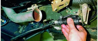
Repair kit for master brake cylinder
It was decided not to change it, but to purchase a repair kit for the main brake cylinder and repair it ourselves. After two days of operation, the cylinder literally jammed. After disassembling it turned out that the rubber bands were swollen. The same thing happened with the second repair kit. The third one lasted a week, but still refused, since the rubber bands had simply worn out.
The main brake was inspected for damage and scratches. We were unable to find anything suspicious. Repair kits were purchased in different price categories, in different stores, and everyone praised the product. Conclusion, they are selling Mr. It's a pity for the money spent, almost a third of the price of a new one.
Causes
The need to pump may arise for several reasons:
- air has entered the brake system;
- the main brake cylinder (GTC) has been replaced or repaired;
- replacement or repair of working brake cylinders;
- repair of the brake system (pipes, hoses);
- the pedal falls through without any visible fault;
- fluid change.
Of course, if only one working cylinder was repaired, there is no point in bleeding the entire system. If the gas turbine engine has been replaced, then full maintenance is necessary.
Source
Working brake system of UAZ Bukhanka
Service brake system diagram
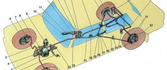
The diagram allows you to study how the brake system of the UAZ Bukhanka works more clearly.
Fig. 1 Diagram of the working brake system of the UAZ Bukhanka: 1 – brake disc; 2 – front wheel brake bracket; 3 – outline of the front part; 4 – main brake cylinder; 5 – reservoir equipped with a brake fluid movement sensor to the emergency level; 6 – amplifier with vacuum; 7 – pusher; 8 – brake pedal; 9 – light switch when braking; 10 – rear wheel brake pads; 11 – rear wheel braking cylinder; 12 – outline of the rear part; 13 – casing of the axle axle at the rear; 14 – load spring; 15 – pressure regulator; 16 – rear cables; 17 – equalizer; 18 – central cable; 19 – parking brake lever; 20 – indicator of brake fluid movement to the emergency level; 21 – parking brake warning switch; 22 – front wheel brake pads.
Hydraulic drive of the service brake system
Since 1985, the hydraulic drive of the UAZ service brake system began to be produced with two separate branches, one of which extends to the brake mechanisms of the front wheels, and the second extends to the brake mechanisms of the rear wheels. The drive design includes:
- master brake cylinder;
- a brake pedal, which is connected to the cylinder through its piston;
- wheel cylinders of wheel brake mechanisms, both in the front and rear of the car;
- pipelines and hoses that connect all cylinders;
- control pedal and drive force amplifiers.
The lines, the inside of the master cylinder, and all wheel cylinders contain brake fluid.
When installing a brake force regulator and an anti-lock braking system modulator on a UAZ, they are also placed in the hydraulic drive structure.
The principle of operation of the UAZ brake system
When you press the pedal, the brake system operates in the following sequence:
- The master cylinder piston moves fluid into the lines and wheel cylinders;
- in the wheel cylinders, the brake fluid causes all the pistons to move, as a result of which the brake pads move closer to the drums;
- when there is no distance left between the pads and the drums, the release of fluid from the main brake cylinder will stop;
- When you press the pedal harder, the fluid pressure in the drive rises and braking of all wheels starts at the same time.
Greater force applied to the pedal results in greater pressure exerted by the master cylinder piston on the fluid, as well as greater force exerted by all the wheel cylinder pistons on the brake shoe.
This suggests that the simultaneous operation of all brakes and the regular relationship between the force on the brake pedal and the driving forces of the brakes are created thanks to the hydraulic drive system.
When the brake pedal is released, it returns to its original position due to the functioning of the return spring. In addition, due to the spring, the piston of the main brake cylinder also moves to its original position. And the tension springs of the mechanisms, in turn, move the pads away from the drums. Brake fluid from the wheel cylinders is pushed through pipelines into the master cylinder.
Advantages and disadvantages of hydraulic drive
Advantages of hydraulic drive:
- quick response provided by the impressive rigidity of the pipelines;
- high efficiency, since energy is wasted as a result of pouring low-viscosity liquid from one device to another;
- not a complex design;
- low weight and dimensions as a result of high driving pressure;
- comfortable layout of drive devices and pipelines;
- a chance to achieve the required distribution of braking forces among the vehicle axles, obtained due to the difference between the diameters of the pistons of the wheel cylinders.
Among the disadvantages of the hydraulic drive are:
- requires special brake fluid with a high boiling point and low thickening point;
- the threat of malfunctions due to depressurization as a result of liquid leakage when damaged, or malfunctions when filling the drive with air;
- a strong decrease in efficiency at low temperatures, usually below minus 30 °C.
Brake fluid
Special brake fluids are sold for use in hydraulic drives. They are produced on alcohol, glycol or oil bases. It is prohibited to mix them with each other; this can lead to a deterioration in their quality and the appearance of flakes. Brake fluids made from petroleum products may only be used in hydraulic drives whose seals and hoses are made of oil-resistant rubber. This is done in order to prevent the destruction of rubber parts.
How does the GTZ function?
The unit consists of the following parts:
- metal housing with holes for supplying brake fluid, pedal rod and connecting the expansion tank;
- 2 pistons with rubber seals;
- 2 return springs;
- guide bushings;
- end plug with gasket.
An expansion tank is attached to the top of the main distributor body, where excess fluid goes through compensation holes. Inside, the element is divided into 2 cylinders with separate pistons standing on the same axis.
The blind end of the housing is closed with a threaded plug; on the other side there is a flange for attaching to the vacuum booster. The brake pedal rod is attached to the first piston. The brake circuit pipes are connected to the lower holes - separately for the front and rear wheels.
The operating principle of the master brake cylinder looks like this:
- When you press the pedal, both pistons simultaneously move forward and push fluid into the circuit tubes. Under its pressure, the wheel cylinders are activated, compressing the pads on the discs.
- Part of the liquid that does not have time to pass into the tubes flows into the expansion tank through special bypass holes.
- When the driver releases the pedal, the springs push the pistons back, returning them to their original position. Liquid from the tubes and reservoir refills the cylinders.
- To compensate for the expansion of the liquid (for example, from heating), another pair of holes is provided leading to the expansion tank.
Note. The GTZ acts in conjunction with a vacuum booster (not shown in the diagram), which helps put pressure on the pistons. This allows the system to respond faster and make the driver's actions easier.
Parking brake system of UAZ vehicles
Parking mechanism diagram
Rice. 2 Parking brake system: a – view with brake drum; b – view without brake drum; 1 – adjustment fork; 2 – lock nut; 3 – drive rod; 4 – expansion cracker; 5 – plug; 6 – drive lever; 7 – adjustment screw; 8 – block support; 9 – pusher of the expansion unit; 10 – ball body; 11 – housing of the expansion unit; 12 – brake drum; 13 – first block; 14 – tension spring of pads; 15 – cap; 16 – expansion unit ball; 17 – bolt; 18 – second block; 19 – brake shield; 20 – housing of the adjustment mechanism; 21 – rod; 22 – spring; 23 – spring cup.
Operating principle of the parking mechanism
The brake mechanism of the parking system is equipped on the transfer case and brakes the rear propeller shaft of the Bukhanka. Its design includes a support disk with two pads installed on it, connected by springs. The pads act on the brake drum, which is fixed on the centering belt of the propeller shaft flange. Attached to the top of the support disk is the housing of the expansion unit with pushers, which are attached to the top of the pads. Inside, the pushers are equipped with recesses filled with balls that are located in the rod. The housing of the adjusting element is installed at the bottom of the support disk. The recesses of the housing contain pad supports that can move due to the work of the block and the adjusting screw.
The brake mechanism drive includes a lever mounted on the support disk and an expansion element supporting the rod of the balls. The free end of the lever is attached to the fork, which in turn is attached to the rod using a lock nut. The drive rod is attached to the parking brake lever, which is installed in the driver’s cab.
In addition, on the UAZ Bukhanka, the parking brake system drive is supplemented with an extension located between the parking brake lever and the brake mechanism. This extension cord is a steel cable with elements for its fastening.
When the brake pedal is released, one of the wheels slows down
The following reasons are suspected: jamming of the wheel cylinder piston, swelling of the brake cups, deformation of the brake pipe, jamming of the pads due to contamination of the guide, peeling of the brake pad lining of the drum brake. It happens that the tension spring of the drum brake shoes is weakened or broken, the parking brake is overtightened, or the cable is stuck in the sheath.
- Do you know which faults you can drive with and which ones you cannot? Take the test and check your driving skill level.
- To increase the life of your car, use additives from SUPROTEC. Original SUPROTEC products can be purchased at.
Parking brake UAZ-469
Contents of the material
Schematic diagram of the brake circuit of UAZ 3163
On an SUV, the braking system is hydraulic, that is, the functioning of the working elements occurs by increasing the fluid pressure in the brake circuit. In the diagram, number 1 shows the front brake disc, with the help of which the wheels are braked when the brake pads (22) act on it. The caliper (2) serves as the main element in which the front pads are installed, as well as cylinders with pistons. The pistons act on the pads as the pressure in the chain increases.
Number 9 shows a contact that closes when you press the brake pedal and the stop light comes on. Pushrod 7 is a steel base that connects the brake pedal to the working piston. The working drive is located in amplifier 6, through which fluid is supplied to the main components of the braking circuit. The chain contains a plastic transparent tank (5), which is filled with liquid. When the liquid level in the tank drops below normal, electrical contact 20 is triggered and the warning light on the UAZ Patriot instrument panel lights up.
From the main cylinder 4, fluid flows through lines 3 to all working units (front and rear wheels). Pressure regulator 15 is designed to automatically change the amount of force. The pressure regulator supplies brake fluid to the rear circuit. The rear circuit consists of a cylinder 11, a piston, two pads 11. They are installed in a drum, and when you press the brake pedal or when you press the handbrake, the pads are pressed against it.
The parking system is presented in the form of a lever or handbrake 19, when released, contacts 21 are closed and the warning light on the instrument panel is activated. A steel cable 18 is connected to the handbrake, which is tensioned when the lever is pressed. Under the bottom of the UAZ Patriot there is an equalizer 17, to which two steel cables 16 are connected from the rear wheels. When you squeeze the handbrake, the main cable is tensioned, and it activates the rear devices. The cables activate the blocks, thereby securing the car in a stationary state.
Amplifier
The vacuum booster is a steel housing located under the hood. The body is divided into two parts - vacuum and atmospheric. The vacuum booster also has a chamber connected to the device thanks to a check valve and an intake manifold. The design of the vacuum amplifier has a piston that moves under the influence of a pusher. Thus, the operating principle of this product is based on the formation of a pressure difference in both chambers. Thanks to this difference, the impact is exerted on the pusher and the cylinder piston. As a result, a slight application of force creates pressure in the circuit that is capable of stopping a moving vehicle.
The vacuum amplifier becomes unusable over time and needs to be replaced. The catalog number of this product for the UAZ Patriot car is 3163-3510010. You can check the serviceability of the product by pressing the brake pedal all the way 2-3 times. With the pedal pressed all the way, you need to start the engine and see if the pedal moves forward, then the device is working properly, and if not, then you need to check the tightness of the product and its serviceability.
In conclusion, it should be noted that the serviceability of the brake chain on a Patriot SUV is the key not only to a sense of confidence on the road, but also to the safety of the driver and passengers.
Symptoms of problems
The fluid brake system consists of many parts that can become unusable: pipes, wheel cylinders, calipers, drums and pads. Typical signs of a faulty master cylinder:
- After pressing the pedal, the car stops slowly. The reason is that the cuffs of one or two pistons have lost their tightness - they have cracked or “floated”.
- To slow down, you need to press the brake pedal hard. The phenomenon occurs due to swelling of the rubber of the piston seals.
- The brake pedal travel is too short. The fluid inside the cylinder has nowhere to go because the compensation hole is clogged. Another option is that the passage is blocked by a swollen rubber seal.
- A common symptom is pedal failure, the brakes coming on at the end of the stroke. This indicates complete wear of the cuffs; as a result, liquid penetrates behind the piston and rushes into the expansion tank - the cylinder “bypasses.”
- The pads do not release the brake discs and drums and get very hot when driving. Options: one of the pistons is jammed or the bypass hole is clogged.
Replacing UAZ 469 brakes, UAZ 469 brakes, 31512, 31514, 31519
Task: replace drum brakes with disc brakes on the UAZ 469 and eliminate the squeaking noise when braking.
Progress of work on replacing brakes on UAZ 469
Preparing calipers for installation
I cleaned it, painted it with thermal paint, and installed a new repair kit.
Dries quickly, but according to the instructions you need to heat it up for full effect.
The complexity of the process is “3” if you prepare well beforehand and, as always, you won’t be able to do it without an angle grinder.
We remove everything unnecessary
The first to be the plan washer (the back wall was smeared with sealant)
We place a special ring inside the trunnion
We put on the trunnion
Screw on the oil deflector
We change the military hub, repressing the bearings and installing the Kortek oil seal
oil seal marking
Next is the drive from 3160
Next, we install the bracket and begin to try on the caliper. The fact that it won't fit is a fact. You will have to remove both from the caliper itself and from the final drive.
Achieving free movement of the caliper
We make an adapter for the Volga hose for UAZ or VAZ 21021
We tighten the hub nuts and install the clutch
A bit of a rut
Result: disc brakes are installed on the UAZ 469.
https://www.drive2.ru/l/6397395/
next article:
Noise when braking
High-frequency noise, squealing, and whistling can occur both during braking and, sometimes, during normal movement. The reason is the off-design mode of friction of the friction material on the working surface of the brake disc. Extreme wear on the brake pads and severe corrosion of the brake disc (often on the inside, “invisible” side) may be to blame. It happens that the brake pad lining has peeled off from the base. The list of possible causes continues with contamination of the pads, warping of the disc due to local overheating, improper fastening of the pads in the caliper, left pads or discs, etc.
UAZ-469 car - characteristics, design, repair
Possible options:
- Controls of UAZ-469
- Preparing for work UAZ-469
- Engine mount UAZ-469
- Crank mechanism of the UAZ-469 engine
- Gas distribution mechanism of the UAZ-469 engine
- Lubrication system UAZ-469
- Engine crankcase ventilation system UAZ-469
- Gas exhaust system of the UAZ-469 engine
- UAZ-469 engine cooling system
- Preheater for UAZ-469 engine
- UAZ-469 engine malfunctions
- UAZ-469 frame
- Steering of UAZ-469
- Electrics UAZ-469
- Generator UAZ-469
- Voltage regulator PP132
- Battery UAZ-469
- Starter UAZ-469
- Control and measuring instruments UAZ-469
- Tools and accessories UAZ-469
- Marking UAZ-469
- Lubricants UAZ-469 and UAZ-469B
Utility vehicles UAZ-3741, UAZ-3962, UAZ-3909, UAZ-2206, UAZ-3303 are equipped with working, parking and spare brake systems. A service brake system with drum brake mechanisms on the front and rear wheels, with two separate hydraulic drive circuits to them from a two-chamber master cylinder: one to the brake mechanisms of the front wheels, the other to the brake mechanisms of the rear wheels.
The parking brake system with a drum brake mechanism located behind the transfer case and acting on the rear driveshaft has a manual mechanical drive. The spare brake system consists of each of the hydraulic drive circuits.
Installation of the service brake system of UAZ-3741, UAZ-3962, UAZ-3909, UAZ-2206, UAZ-3303, installation of front and rear brakes.
The front service brakes have two wheel cylinders, each of which acts separately on the pad. Cylinder diameter 32 mm. The rear brakes have one wheel cylinder acting on both pads. Cylinder diameter 25 mm.
Front wheel braking system.
Two wheel cylinders are secured to the brake shield using support pins and nuts. The support pins have eccentrics on which brass pad support bushings are installed. By turning the support pins with eccentrics, you can move the support ends of the pads relative to the brake shield. They adjust the brakes using support pins when assembling them at the factory or when repairing brakes with replacing pads or linings.
When correctly installing the pads with unworn linings and the brake drum, the “a” marks on the support pins (cores on the outer ends) should be located as shown in the figure above, or with deviations from this position in one direction or another up to 50 degrees. The friction linings of the pads are attached to the rim with aluminum rivets recessed into the body of the lining.
The moving ends of the brake pads fit into the grooves of the piston tips of the wheel cylinders. The pads, with the inner surface of their rims, rest on adjusting eccentrics, movably mounted on the brake shield. The eccentrics are kept from arbitrary rotation by strong springs. The pads are pressed against the eccentrics by tension springs.
The hexagonal heads of the adjusting eccentric axes are located on the outside of the brake shield. Using eccentrics, the required gap is established between the pads and the drum. The pads are kept from lateral displacement by the ends of the axes of the adjusting eccentrics and by springs installed in the middle part of the pads.
Inside each wheel cylinder there is a piston with two rubber O-rings and a spring that presses the wheel cylinder piston against the thrust end of the pad rib. The wheel cylinder has two holes. One hole is used to supply brake fluid from the hydraulic drive system, and the other is to release air from the system during bleeding.
It is closed by a bypass valve, which in the closed position ensures a tight seal. To prevent clogging, the valve opening is closed with a protective cap. The internal cavities of the wheel cylinders are protected from moisture, dust and dirt by rubber caps.
Rear wheel braking system.
In the lower part of the brake shield there are support pins, which are fitted with brass bushings similar to those of the front brakes, against which the pads swing. When correctly installing the pads with new linings and drums, the “a” marks on the supporting pins (cores on the outer ends) should be located as shown in the figure below, or with deviations from this position in one direction or another up to 50 degrees.
The rear brake pad lining is shorter than the front brake pad lining. This is designed to ensure that the wear on the rear and front pads is equal. Brake drums are the same on all wheels of the car. The drums are attached to the hub with three screws, which are unevenly spaced around the circumference.
This ensures that the drum is installed on the hub in one specific position, in which the drum assembly with the hub is processed. It is not recommended to move brake drums from one hub to another, as this will lead to increased runout of the working surfaces of the brake drum.
Hydraulic drive of the service brake system of UAZ-3741, UAZ-3962, UAZ-3909, UAZ-2206, UAZ-3303, device.
Consists of a suspended pedal, a vacuum booster, a two-chamber master cylinder, pipelines with connecting fittings and wheel working cylinders. The hydraulic drive pedal to the wheel brake mechanisms, as well as the clutch release pedal, swings on an axle on a plastic bushing, requiring no lubrication during operation.
The axis is fixedly fixed in the bracket. The return spring constantly holds the pedal in its original position by pressing it against the brake light switch cap mounted on the pedal bracket. The brake pedal is connected through a system of shafts and rods to the pusher of the vacuum booster.
Vacuum booster of the service brake system.
Serves to increase the efficiency of hydraulic brakes when the engine is running. If the amplifier fails, only the force from the driver's foot is transmitted to the pistons of the master cylinder through the brake pedal, pushrod, control valve, buffer and rod. The vacuum booster does not require adjustments.
Maintenance consists of checking the reliability of fastening, washing or replacing the amplifier air filter during seasonal maintenance before the winter operating season.
Service brake system pressure regulator.
Automatically adjusts the brake fluid pressure in the rear wheel brake circuit depending on the load on the vehicle, preventing the vehicle from skidding due to the rear wheels locking during heavy braking. It may not be installed on some modifications of UAZ-3741, UAZ-3962, UAZ-3909, UAZ-2206, UAZ-3303 vehicles.
Double-chamber master cylinder of the service brake system.
Serves to simultaneously create pressure in both circuits of the hydraulic brake drive when pressing the brake pedal. The master cylinder chambers are supplied with brake fluid from a reservoir mounted on the cylinder body. Each of the pistons has its own return spring. The relative position of the pistons is limited by a limiter sleeve and a screw.
Sources used:
- https://avtoremontnikam.ru/hodovaya/zamena-tormoznogo-cilindra-uaz.html
- https://pulyaet.ru/remont/tormoznaya-sistema-uaz-452-buhanka
- https://7gear.ru/avtomobili/glavnyj-tormoznoj-cilindr-uaz.html
- https://auto.kombat.com.ua/rabochaya-tormoznaya-sistema-uaz3741-3962-3909-2206-3303-pered-zadn-tormoza-gidroprivod-torm/
Tool
To carry out the work you must have:
- brake fluid, usually DOT4 or the one that is poured into the system;
- a clean container for collecting fuel fluid;
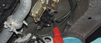
- hose for draining fluid from brake cylinders;
- key 10, unscrew the bypass valve.
The hose or tube must be such that it fits tightly onto the bypass valve and has a length of 40 centimeters.
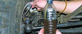
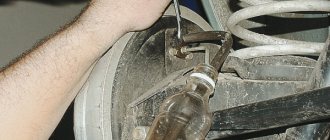
Bleeding the brakes of the rear right wheel of the UAZ