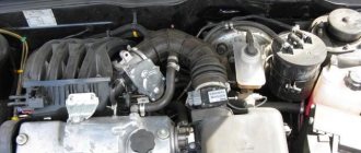
The braking system of a car as a whole is one of the most important elements that allows you to protect the driver and passengers from many troubles. For this reason, it is extremely important to maintain it in working order and carry out regular maintenance.
In this article we will talk about how the brake system works on the VAZ-2115 car (injector).
Checking and adjusting brakes
Checking pipes and connections
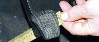
To prevent sudden failure of the brake system, carefully check the condition of all pipes and connections, paying attention to the following:
— metal pipelines should not have nicks, scratches, chafing, active foci of corrosion and should be located away from sharp edges that could damage them;
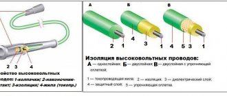
— brake hoses must not have any cracks on the outer shell or signs of chafing visible to the naked eye; they should not be exposed to mineral oils and lubricants that dissolve rubber; by pressing the brake pedal firmly, check to see if any swelling appears on the hoses, indicating their destruction;
— all pipeline fastening brackets must be intact and well tightened; loosening or destruction of brackets leads to vibration of pipelines, causing their breakdowns;
— liquid leakage from the connections of the master cylinder with the tank and from the fittings is not allowed; if necessary, replace the tank bushings and tighten the nuts without subjecting the pipelines to deformation.
When tightening the pipeline nuts, use wrench 67.7812.9525.
Eliminate any detected faults by replacing damaged parts with new ones.
Flexible hoses, regardless of their condition, should be replaced with new ones after 125,000 km or after five years of vehicle operation to prevent sudden ruptures due to aging.
Checking the functionality of the vacuum booster
Press the brake pedal 5-6 times with the engine off to create equal pressure, close to atmospheric, in cavities “A” and “B” (see Fig. 6-2). At the same time, by the force applied to the pedal, determine whether the valve body is jammed.
Keep the brake pedal depressed and start the engine. If the vacuum booster is working properly, the brake pedal should “move forward” after starting the engine.
If the brake pedal does not “go forward”, check the fastening of the hose tip, the condition and fastening of the tip flange in the amplifier, the hose to the tip and the fitting of the engine intake pipe, since loosening the fastening or their damage sharply reduces the vacuum in cavity “A” and the efficiency of the amplifier .
Adjusting the brake drive
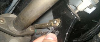
The free play of the brake pedal when the engine is not running should be 3-5 mm. The adjustment is carried out by moving the brake light switch 10 (Fig. 6-11) with nuts 8 and 9 loosened. Install the switch so that its buffer rests against the pedal stop, and the free play of the pedal is 3-5 mm.
8 In this position of the switch, tighten nuts 8 and 9.
Rice. 6-11. Brake drive: 1 —
master cylinder; 2 - tank; 3 — emergency liquid level sensor; 4 - vacuum booster; 5 - pusher; 6 — brake pedal; 7 — brake light switch buffer; 8, 9 — brake light mounting nuts; 10 — brake light switch; 11 — pedal return spring
WARNING. Adjust the brake pedal free play when the engine is not running.
If the brake light switch is too close to the pedal, it will not return to its original position. In this case, valve 18 (see Fig. 6-2), pressing against body 21, separates cavities “A” and “B” and the wheels are incompletely released when the pedal is released.
If by moving the brake light switch it is not possible to eliminate the incomplete release of the brake mechanisms, then disconnect the brake master cylinder from the vacuum booster and check the protrusion of the adjusting bolt 4 relative to the mounting plane of the master cylinder flange (size 1.25 -0.2 mm). This size can be set by holding the end of the rod with a special wrench and tightening or unscrewing bolt 4 with another wrench.
Adjusting the parking brake system
Diagram of the rear wheel brake system of the VAZ 2114
The design of the rear brake mechanism on the VAZ 2114
1
.
Hub nut 2
.
Hub flange. 3
is attached to it .
Lower tension spring 4
.
Left block 5
.
Thrust spring 6
.
Cylinder 7
.
Upper tension spring 8
.
Guide bar 9
.
Eccentric 10
.
Right block 11
. Pad cover.
Tip: when driving through deep puddles or fording a river, the brakes get wet. This dramatically reduces braking efficiency. Immediately after overcoming a water obstacle on a straight section and at low speed, brake several times. The pad linings, discs and drums will become hot and dry. The system's efficiency will be restored.
In general, the braking system of the VAZ-2114 is simple and reliable. For a person who has experience driving cars of other brands, servicing it on a “fourteen” will not be a problem. But even those drivers who got behind the wheel of a car for the first time can easily understand the operating principle and operating features of the VAZ-2114 brake system. But remember: it is better to service the brake system at warranty service stations from experienced technicians.
Device
The VAZ-2115 uses a brake system in which the operating circuits are divided diagonally. This can significantly increase the degree of reliability and safety of people. In particular, the first of them controls the operation of the front right and rear left brake mechanisms. If it fails, the second circuit is switched on.
In addition, the hydraulic drive operating diagram also includes:
- vacuum booster;
- a dual-circuit regulator whose task is to maintain pressure in the brakes located behind.
A sensor is installed on the VAZ-2115 that signals a decrease in brake fluid volumes. It's mechanical. In addition, there is also a parking brake system, which, in turn, has a separate drive that blocks the rear axle if necessary.
As can be understood from the diagram, the system in question is quite complex, and from time to time certain breakdowns occur in it.
To understand what kind of problem arose at one time or another requires quite a lot of experience. However, it is not difficult to make the diagnosis yourself if you use the recommendations below.
Diagram of the front wheel brake system of the VAZ 2114
The design of the front brake mechanism on the VAZ 2114
The front brake mechanism consists of the following components:
1
.
Brake disk. Directly connected to the wheel hub and rotates with it. Slowing down the rotation and stopping the disk leads to the slowing down and stopping of the wheel. 2
.
Pad guide. Serves as a holder for the pads and a base for the guide pins. 3
.
Caliper. It combines the pads, cylinder, and piston into a single unit and ensures uniform transmission of force from both pads to the disc. 4
.
Brake pads. They directly act on the disc, squeezing it on both sides and slowing down the movement. 5
.
Cylinder. A sealed cavity in which the piston moves. 6
.
Piston. Under the influence of hydraulic fluid pressure, the pad is pressed against the disc. Thanks to the “floating clamp” system, the second block is pressed simultaneously. This ensures uniform wear of their linings and discs and guarantees effective braking. 7
.
Seal ring. Prevents fluid leakage and ensures system tightness. 8
.
A cover to protect the guide pin from dirt, allowing for unhindered movement of the pads. 9
.
Guide finger. Allows the pads to move evenly and adhere to the disc with their entire plane. 10
. Protective cover. Protects the disc from road dirt. The front wheels are equipped with disc brakes. They automatically adjust the clearance from the pad to the disc. The caliper and cylinder form a floating caliper, which creates the same even force on both pads. This ensures uniform wear of the linings. To monitor their wear, there is an indicator on the inner block.
The brake pedal has too much travel
In this case, one might suspect that:
- air has entered the hydraulic drive;
- the rear cylinder piston thrust ring lost elasticity, as a result of which it shifted inward;
- Brake fluid has leaked from the system;
- There is too much clearance between the main cylinder piston and the vacuum booster adjusting bolt.
- in the first case, you will need to bleed the system;
- in the 2nd - you will need to completely change the cylinder;
- in the 3rd - eliminate the leak by replacing seals or hoses that have become unusable.
Brake performance is low
The most common reasons for this problem are:
- brake pads are oily;
- pistons jam in wheel cylinders;
- the linings on the blocks have become unusable;
- the brake system mechanisms overheated;
- the pressure regulator was set incorrectly;
- one of the circuits has lost its tightness.
The linings on the brake pads will need to be cleaned using a wire brush, warm water and washing powder.
If the pistons jam, you will have to change the cylinders and bleed the system.
When the linings wear out, they need to be removed and new ones installed.
Overheating of the system is eliminated by immediate shutdown. It will take some time for it to cool completely.
Why the wheel mechanisms are not fully released
Most likely, this malfunction will cause the brake pedal to stick. In this case, you will have to adjust it.
In addition, the disappearance of the gap between the piston in the master cylinder and the vacuum booster adjustment bolt may also be the cause. The problem is eliminated by increasing the lumen.
If fuel or oil gets into the brake fluid, the gaskets in the master cylinder sometimes swell. You will need to flush the entire system with new brake fluid and replace seals that have become unusable.
Braking of one of the wheels is observed when driving
Most often, such a breakdown is caused by the destruction of the tension spring on the rear brake. The damaged one will have to be removed and a new one put in its place.
It is also common for pistons in wheel cylinders to not function properly if dirt has gotten inside or they have begun to rust. Cleaning and rinsing will eliminate the problem.
Sometimes braking occurs due to loosening of the bolts that secure the guide pads directly to the steering knuckle. If they are re-tightened or replaced with new ones, the problem will be eliminated.
And finally, this can happen because the parking brake system has not been adjusted correctly.
Design features of the brake system of the VAZ-2115, Brake system
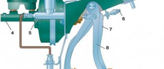
8.1. Hydraulic brake circuit diagram:
A – flexible hose of the front brake; B – flexible hose of the rear brake; 1 – front wheel brake mechanism; 2 – left front–right rear brake circuit pipeline; 3 – main cylinder for hydraulic brakes; 4 – pipeline of the right front–left rear brake circuit; 5 – master cylinder reservoir; 6 – vacuum booster; 7 – rear wheel brake mechanism; 8 – elastic lever of the pressure regulator drive; 9 – pressure regulator; 10 – pressure regulator drive lever; 11 – brake pedal
The car uses a working brake system with diagonally separated circuits (Fig. 8.1), which significantly increases the safety of driving the car. One hydraulic drive circuit ensures the operation of the right front and left rear brake mechanisms, the other - the left front and right rear. If one of the circuits of the service brake system fails, the second circuit is used to stop the vehicle with sufficient efficiency.
The hydraulic drive includes a vacuum booster 6 and a dual-circuit pressure regulator 9 in the rear brakes.
The parking brake system is driven by the brake mechanisms of the rear wheels.
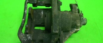
8.6. Front wheel brake:
1 – brake disc; 2 – pad guide; 3 – caliper; 4 – brake pads; 5 – working cylinder; 6 – piston; 7 – sealing ring; 8 – protective cover of the guide pin; 9 – guide pin; 10 – protective casing
Front wheel brake
disc, with automatic adjustment of the gap between the pads and the disc, with a floating bracket.
The bracket is formed by caliper 3 (Fig. 8.6) and working cylinder 5, tightened with bolts. The movable bracket is bolted to pins 9 installed in the holes of the shoe guide. Lubricant is placed in these holes, rubber covers 8 are installed between the pins and the pad guide. The brake pads 4 are pressed against the grooves of the guide by springs.
A piston 6 with a sealing ring 7 is installed in the cavity of the cylinder 5. Due to the elasticity of this ring, the optimal gap between the brake pads and the disc is maintained. In a variant, cars can be equipped with pads with a pad lining wear indicator.
8.7. Rear wheel brake:
1 – hub fastening nut; 2 – wheel hub; 3 – lower tension spring of the pads; 4 – brake pad; 5 – guide spring; 6 – working cylinder; 7 – upper tension spring; 8 – expansion bar; 9 – finger of the parking brake drive lever; 10 – parking brake drive lever; 11 – brake shield
8.8. Rear wheel brake working cylinder:
A – slot on the thrust ring; 1 – block stop; 2 – protective cap; 3 – cylinder body; 4 – piston; 5 – seal; 6 – support plate; 7 – spring; 8 – crackers; 9 – thrust ring; 10 – thrust screw; 11 – fitting
Rear wheel brake
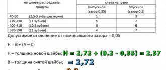
(Fig. 8.7) drum, with automatic adjustment of the gap between the shoes and the drum. The automatic clearance adjustment device is located in the working cylinder. Its main element is a split thrust ring 9 (Fig. 8.8), installed on the piston 4 between the shoulder of the thrust screw 10 and two nuts 8 with a gap of 1.25–1.65 mm.
The thrust rings 9 are inserted into the cylinder with tension, providing a shear force of the ring along the cylinder mirror of at least 343 N (35 kgf), which exceeds the force on the piston from tension springs 3 and 7 (see Fig. 8.7) of the brake pads.
When, due to wear of the linings, the gap of 1.25–1.65 mm is completely selected, the shoulder on the thrust screw 10 (see Fig. 8.8) is pressed against the shoulder of the ring 9, as a result of which the thrust ring moves after the piston by the amount of wear. When the braking stops, the pistons are moved by the force of the tension springs until the cracks stop against the shoulder of the thrust ring. This automatically maintains the optimal gap between the pads and the drum.
8.9. Parking brake system drive:
1 – lever fixation button; 2 – parking brake drive lever; 3 – protective cover; 4 – traction; 5 – cable equalizer; 6 – adjusting nut; 7 – lock nut; 8 – cable; 9 – cable sheath
Parking brake system
with a mechanical drive, acts on the brake mechanisms of the rear wheels. The parking brake drive consists of lever 2 (Fig. 8.9), adjusting rod 4, equalizer 5, cable 8, lever 10 (see Fig. 8.7), manual pad drive and expansion bar 8.
8.10. Emergency brake fluid level sensor:
1 – protective cap; 2 – sensor housing; 3 – sensor base; 4 – sealing ring; 5 – clamping ring; 6 – reflector; 7 – pusher; 8 – bushing; 9 – float; 10 – fixed contacts; 11 – moving contact
Emergency brake fluid level sensor
mechanical type.
Housing 2 (Fig. 8.10) of the sensor with seal 4 is pressed to base 3 by clamping ring 5 screwed onto the neck of the tank. At the same time, the reflector flange 6 is pressed against the end of the neck. In this position, the clamping ring is held by two clamps made on the base 3.
A pusher 7 passes through the base hole, connected to the float 9 using a bushing 8. There is a movable contact 11 on the pusher, and fixed contacts 10 are located on the sensor body. The contact cavity is sealed with a protective cap 1.
When the level of brake fluid in the reservoir drops to the maximum permissible level, the moving contact moves down onto the fixed contacts and closes the circuit of the brake system emergency warning lamp in the instrument cluster.
Useful tips: There are two ways to bleed the brakes without an assistant.
- The first is the most reliable: order a turner an aluminum or bronze cover for the main brake cylinder, screw the valve from the brake chamber into it and connect it to the spare wheel with an additional hose; air pressure should not exceed 0.05–0.07 MPa (0.5–0.7 kgf/cm2).
- The second is not very reliable, but acceptable: connect the rubber bulb to the wheel cylinder fitting - the connection should be very tight. Squeeze the bulb, unscrew the fitting; When the bulb is half full, tighten the fitting. Repeat the procedure 3-4 times. During test braking, check the operation of the brakes.
The free play of the brake pedal when the engine is not running should be 3–5 mm. Too little free play indicates sticking of the wheel cylinder and causes increased fuel consumption and accelerated wear of the brake pads; too much free play is a sign of excessive clearances in the pedal mechanism or a leak in the brake system.
If the free play decreases when pressing the pedal repeatedly, i.e. it becomes “harder” - there is air in the system. If the full pedal travel begins to increase, the system is leaking.
If the brake pedal begins to vibrate when braking, it is most often due to warped brake discs. Unfortunately, in such a situation they only need to be changed, and both at once.
If the car starts to pull to the side when braking, check the wheel cylinders: they may need to be repaired or replaced.
If there is a knocking noise in the front suspension that goes away when braking, check the tightness of the two caliper mounting bolts.
After replacing the brake pads, be sure to press the brake pedal several times before driving to ensure that the pistons in the wheel cylinders are in place.
◀Bleeding the brake system VAZ-2115, Brake system
Checking the operation of the check valve of the vacuum booster VAZ-2115, Brake system▶