Automakers strive to ensure that the operation of the vehicle brings safety, comfort and pleasure to the driver, and is also quite economical. In this regard, cars are constantly being modernized. A modern car in its design has many different electronic devices and instruments that convert the indicators of the value specified for measurement and direct the data into the “electronic brain of the vehicle.” In turn, the machine’s ECU processes all the information received by it and, in accordance with the specified settings, gives a command to the electronic systems about the need for adjustments in operation.
The camshaft position sensor (CPS) of the VAZ 2112 is one of the most critical elements of the car’s electronic system - it monitors the phases of operation of the cylinder-piston group and, as a result, influences the optimal operation of the internal combustion engine.
Purpose and principle of operation of the DPRV
The position sensor is designed to determine at a specific moment in time the position angle of the timing shaft. The obtained indicators are sent to the control unit, and after their processing, the operation of the automobile engine is adjusted to increase the efficiency and completeness of combustion of the combustible mixture. The result of the device is an increase in vehicle power, economic indicators and improvement of other characteristics.
DPRVs differ not only depending on the make and model of the car, but for different engines, for example, for eight- and sixteen-valve internal combustion engines.
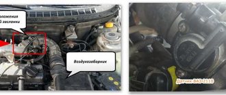
To get an answer to the question of where the camshaft sensor (phase sensor) is located on a VAZ 2112 16 valves, just open the hood and carefully examine the internal combustion engine - it is located in the area of the timing shaft.
A rotor made of ferromagnetic material rotates together with the camshaft. Between the rotor and the permanent magnet is a Hall IC. When the protrusion passes by the DPRV element, the level of magnetic field strength changes, a voltage of a certain strength is induced and a signal is created, which is sent to the ECU for subsequent analysis.
Crankshaft regulator
Depending on the type of car, on a 16- and 8-valve engine, the location of all controllers may be different. However, all of these devices combine into one functioning system, and the crankshaft adjuster is no exception. Thanks to this controller, the electronic engine management system of the “tens” can independently determine at what point to supply gasoline and a spark through the spark plugs in order to ignite the combustible mixture. In fact, the design of the device is a magnet, as well as a coil of thin wire.
The crankshaft sensor has certain advantages:
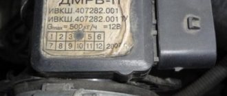
- As practice shows, at “tens” this regulator can work for quite a long time. Its service life does not decrease even as a result of using the vehicle’s power unit under increased loads.
- The crankshaft adjuster works in conjunction with the crankshaft pulley.
- If the device fails, the engine may not be able to start. Or, if the regulator breaks down, the speed parameters will be reduced to 3.5 thousand per minute.
This controller is installed on the oil pump, actually at the very top of the shaft teeth. Or rather, one millimeter from the cloves. You can learn more about how to replace this controller yourself from the video below (the author of the video is the channel In Sandro’s Garage).
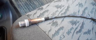
Signs of DPRV failure
Over time, the phase sensor on the VAZ stops functioning correctly. Natural wear and tear is the main, but not the only reason for device failure. Signs of malfunction are easy to identify. It is enough to pay attention to how the car engine works. The first start of the internal combustion engine will be difficult and, instead of the usual “grabbing”, it will occur after a long period of torsion of the starter. During the operation of the vehicle, its power noticeably decreases, during acceleration “dips” in dynamics are observed, and instability in engine operation is periodically felt. In addition, motor fuel consumption increases significantly. This happens because the “electronic brain” issues commands for the fuel supply system and the moment of its ignition, based on incomplete data, thereby fuel injection is carried out under non-ideal operating conditions. Also, the “SNACK” signal will light up on the dashboard, which indicates the need to conduct a computer check of the vehicle systems. On some vehicles it is possible to lock the gearbox in one position.
These symptoms indicate problems that have arisen in the operation of the internal combustion engine, and the need for urgent comprehensive diagnostics to identify the exact cause of their occurrence.
When diagnosing a car with a computer, a phase sensor error will be indicated by one of the following codes stored in memory: P0300, P0340, P0341, P0342, P0343, P0344, P0365.
A little history
The VAZ 2110 was produced from the end of the 20th century until the middle of the first decade of the 21st century. During its existence, the top ten managed to gain a huge number of fans and underwent a large number of changes.
The tenth VAZ family was initially equipped with 8-valve carburetor engines that had common roots from the G8 engines. Time moved forward and AvtoVAZ needed to develop further, and at the end of the 90s, an injection engine was installed on the top ten for the first time, which was distinguished not only by a new injection system, but also by the number of valves; some new engines received a doubled number of valves from 8- mi to 16.
To operate an engine with an injection system, you need a huge number of different sensors responsible for the operation of the internal combustion engine, and the VAZ 2110 is no exception; the dozens of injection engines have many different sensors installed that ensure correct and smooth operation of the engine.
In this article we will talk about VAZ 2110-12 sensors, their symptoms of malfunction and installation locations.
Reasons for sensor failure
A DPRV malfunction can occur for several reasons, and replacing it will not always solve the problem. The reasons why the device does not work may be the following:
- lack of contact between the device and the signal wire;
- the presence of moisture at the connection point of the DPRV;
- violation of the integrity of the wire, including its short circuit;
- incorrect power connection;
- axial timing runout;
- steel shavings on the device body;
- violations in the operation of the internal combustion engine control unit;
- incorrectly set gap.
How to check the phase sensor
Before taking measurements and performing replacement work, it is worth visually inspecting the position sensor and checking the wires for integrity. If, as a result of the inspection, no malfunctions that could affect the operation of the device are identified, it is necessary to check the DPRV.
To find out whether the phase sensor is working or not, you will need some knowledge and ability to use a multimeter. Diagnostics can be carried out in several ways, so as an example, we will consider diagnostic methods for various DPRVs.
- Two-wire device. Operating procedure:
- start the internal combustion engine;
- switch the voltage measurement mode on the multimeter to the AC voltage position;
- Connect both wires from the electrical meter to two different terminals on the camshaft sensor. If the voltage fluctuates up to 5 V, then the part is serviceable; if there is no voltage, then replacement is necessary.
- Three-wire device. Operating procedure:
- start the internal combustion engine;
- switch the electrical measuring device to constant voltage mode;
- connect one contact of the multimeter to the black wire on the part, and the second to its power wire. If the voltage indicator is missing, then replacement is made. For a specific car model, the voltage value is indicated in the instruction manual.
The part is non-repairable, therefore, if it is found to be faulty, it is replaced with a new one.
Repair
Checking the camshaft sensor with a multimeter
Before checking the DPRV or before starting any independent actions, you need to familiarize yourself with the connection diagram for the VAZ 2110 camshaft sensor, as well as the features of its installation in the engine body.
The type of action performed depends on what signs of malfunction have been identified:
- if there is visible mechanical damage to the wiring or exposure of live parts, it must be replaced, but repairs in the form of re-insulation of the wires are also possible;
- If the sensor is mechanically damaged, it must be replaced. It is not recommended to repair or disassemble it;
- if the connector is dirty, it is necessary to reconnect with a visual inspection and cleaning of the electrical contacts;
- Wear of the connection connector requires its maintenance or replacement of the sensor. Maintenance consists of ensuring a tight fit of the connected parts;
- When checking the electrical wiring or sensor with a voltmeter and identifying deviations, it is necessary to replace the faulty element. When connecting the voltmeter probes to the electrical power contacts, the sensor resistance should not be lower than 550 Ohms or higher than 750 Ohms;
- If an internal malfunction of the sensor is detected during computer diagnostics, it must be replaced.
Replacing the DPRV is carried out by disconnecting it, dismantling the faulty one, installing a new one and reconnecting the power connector.
It is important to note that after performing any actions aimed at eliminating identified faults, it is necessary to recheck the engine operation. The operating manual does not recommend disabling the sensor yourself and further operating the vehicle.
The operating manual does not recommend disabling the sensor yourself and further operating the vehicle.
Replacing the DPRV
Replacing the phase position sensor of a VAZ 2112 16 valves is not difficult. Fastening to the internal combustion engine is carried out with two bolts, which are unscrewed with a 10mm socket wrench. Let us consider the replacement process step by step.
- We de-energize the car by removing the ground from the battery.
- Remove the terminal block from the sensor.
- Unscrew the fastening bolts with a socket wrench.
- Carefully pull the part and remove it.
- We install a new DPRV and carry out the work in the reverse order.
For proper operation of the position sensor after replacement, the mounting gap must be within 0.5–1.2 mm.
The camshaft sensor for a VAZ is inexpensive, but if you operate a car with a faulty device, this will lead to more complex and expensive breakdowns to repair.
Changing the oil seal
VAZ 2114 speed sensor pinout, connection diagram, testing methods
As for the characteristics themselves, the component must correspond to the dimensions of the part installed in a given car model. If the specifications are not met, you may have to go to the store for a new oil seal in the midst of repairs.
We change it with our own hands
First of all, you should dismantle the VAZ 2110 timing belt. Then you will need a “17” wrench. Take the tool and begin to unscrew the screw that secures the toothed disk of the timing pulley. You need to make sure that the pulley does not turn. To do this, you will need to pass a “10” head through the hole in it, which must be put on an extension cord. Engage the nut securing the rear cover of the timing belt drive. After this, using a screwdriver, pry up the timing pulley disk and dismantle it. At this moment, be careful: under no circumstances should the toothed disk key be lost. Remove it from its installation location. Now, using the same screwdriver, pry up the camshaft oil seal that needs to be replaced and remove it. Take a new oil seal and lubricate its edge and installation location with engine fluid. If you do not lubricate the element itself with oil, the knocking may not go away. To install the component you will need a small piece of pipe
The oil seal will need to be pressed in carefully. You will also need a hammer for this. Carry out all subsequent assembly in reverse order.
Don't forget to align the timing belt correctly.
After completing the repair work, start the engine and check if the knocking noise disappears. If there is no knocking noise, then the whole problem was in the camshaft oil seal.
Actually, this completes the procedure for replacing and eliminating camshaft knock. We strongly advise you not to carry out this work yourself if you do not have enough skills. Incorrect tightening of the timing belt and incorrect alignment of this element to the markings can subsequently cause the belt to break. If this happens while driving, the VAZ 2110 engine valves may bend. As you understand, subsequent repairs will cost a pretty penny.
Video on the topic
Good publicity
The camshaft position sensor is a monitoring device whose functional purpose is to analyze the location of the engine camshaft.
Based on the location of the crankshaft, the ECU calculates the required amount, as well as the time of fuel supply to the internal combustion engine cylinders, and the ignition timing is calculated.
In the design of the power unit, the indicator is installed on the cylinder head block and is additionally marked with appropriate markings. The original camshaft position sensor for the VAZ 2112 model is sold on the Russian market under article number 2112 - 3706040, the average cost of the part is 300 rubles.
It is important to know! This sensor is the only control and measuring device, without which proper functioning the further operation of the engine is impossible.
Design
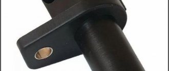
On the VAZ 2110, the camshaft position sensor is made in the form of a cylinder and has an end-mounted operating principle. Its structural elements are:
- plastic case;
- semiconductor wafer;
- secondary converter;
- magnet;
- current-carrying elements.
The DPRV connector has three contacts:
- constant power supply;
- transmission of the read signal to the control unit;
- weight.
Engines on which two camshafts are installed, and the gas distribution mechanism consists of sixteen valves, also have one camshaft position sensor of the same design.
Typical malfunctions of the VAZ 2112 camshaft sensor
This mechanism, as a rule, is immune to the influence of external factors, however, there are a number of typical malfunctions as a result of which the indicator may fail. On a VAZ 2112, the camshaft position control indicator in the engine may fail as a result of:
- There is a breakdown in the main wiring leading to the sensor;
- Overheating of the control element as a result of long-term operation of the car in an overloaded state;
- Moisture or small abrasive elements get inside the device itself.
You can diagnose a malfunction of the camshaft sensor on a car using a number of indirect signs, including:
- A sharp increase in fuel consumption;
- Reduced dynamics of the power unit, loss of power;
- Problematic engine acceleration, reduced traction of the power unit;
- Presence of engine “protrusion”, problems when starting the engine when cold;
- Failure of the engine self-diagnosis mode;
- The check light on the car's dashboard lights up.
If you have one or more factors on your car, it is recommended to check this unit for functionality. The camshaft position sensor is inexpensive and easy to change, but neglecting to replace the faulty element can lead to rapid failure of the power unit.
Remember, improper fuel and ignition supply to the engine reduces the service life of all power unit systems and can cause expensive repairs in the near future.
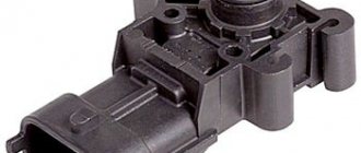
Coolant temperature indicator
Antifreeze or coolant is used to cool the engine. To ensure proper operation of the power unit, the coolant also has its own controller. In its functionality, this regulator is vaguely reminiscent of the choke that is equipped with 8- and 16-valve carburetor engines of the “ten” and other vehicles. The sensor itself is designed to monitor the temperature of the consumable.
Installing a new antifreeze sensor
In fact, this device also provides fuel regulation. If the power unit is running cold and has not yet warmed up, it will receive more gasoline for normal operation. Readings about the coolant temperature are displayed on the control panel in the vehicle interior. In accordance with these indicators, the driver will always be able to find out about the overheating of the unit by the way the sensor arrow on the dashboard begins to move into the red zone.
The antifreeze temperature sensor periodically fails; it is characterized by the following malfunctions:
- Loss of electrical contact inside the controller, resulting in its inoperability.
- The device is installed in such a way that it may be exposed to moving elements, particularly the accelerator pedal cable. It would be even more correct to say that the cable does not act on the sensor itself, but on its wires, which in fact can lose insulation as a result of long-term use.
- Often the regulator breaks down if the ventilation device starts to function on an engine that is not warmed up.
- If the motor is overheated, it may be difficult to start.
- If the fuel temperature controller fails, it can lead to increased gas mileage. If you encounter one of these problems, then to ensure normal operation of the car engine, you need to replace the controller. Detailed replacement instructions are presented in the video below (author - REPAIR VAZ 2110, 2111, 2112).
How to replace a camshaft sensor at home
The procedure for replacing the camshaft sensor will not present any difficulties to the car owner and will take no more than 5-8 minutes. The only thing worth knowing is the exact location of the sensor in the design of the power unit. On a VAZ 2112, this indicator is located on the cylinder head block and immediately catches your eye when you lift the hood.
To replace a faulty camshaft indicator on a VAZ 2112 you need to:
- Disconnect the positive terminal from the battery;
- Next, disconnect the block with electrical wiring from the sensor itself;
- Using an open-end wrench set to “10”, you need to unscrew the clamps fixing the indicator, and then remove the part;
- Now install another part and repeat the assembly procedure in reverse order.
For the proper functioning of this unit, it is not at all necessary to coat the fastening points with sealant or sealing compound, however, it is highly recommended to monitor the quality of the connected wiring.
All 16-valve engines on the 2112 hatchbacks were equipped with the same sensor that reads the camshaft angle. We are talking about the intake camshaft, and the sensor is attached near the pulley of this shaft. It is called a phase sensor. The operating principle is based on the Hall effect, that is, voltage must be supplied to the sensor. On a VAZ-2112 car, you can check the phase sensor only after dismantling. You will also need to check whether the supply voltage is supplied. If necessary, replace it - you need a part with article number 2112-3706040.
The following video shows how the sensor is checked using the express method (not recommended).
Ways to twist mileage
Fraudsters have several techniques in their arsenal to deceive gullible customers. The choice of one method or another primarily depends on the type of device installed on the machine, which is responsible for calculating the distance traveled.
Here it is necessary to clarify and talk about the fact that many inexperienced car owners mistakenly associate the increase in mileage with adjusting the speedometer readings. In fact, it shows the speed of movement, and the number of kilometers traveled by the vehicle is recorded by another device - the odometer.
The device works in close connection with the speedometer. And the panels that display the readings of these two devices are usually located next to each other. Apparently this is where some confusion in concepts arose. In order not to confuse the reader even more, we agree that the use of both definitions is acceptable.
A car can be equipped with one of three types of odometers:
- mechanical;
- electromechanical;
- electronic.
Mechanical and electromechanical devices were used in the automotive industry until the end of the last century. They are distinguished by a rather primitive device: the speed of the gearbox gearbox is transmitted through a special cable to a meter, the readings of which are displayed on the dashboard. It is easiest to check the mileage of such a device.
Method number 1. The odometer is disassembled, and the necessary readings are set on the meter manually.
Method number 2. To implement it, you will need to disassemble the dashboard and attach any power tool with high rotation speed (screwdriver, drill, etc.) to the speedometer cable using a special attachment. After this, the readings are twisted to the desired value. Of course, this can be done manually, but using a power tool speeds up the process many times over.
For an electromechanical odometer, twisting is carried out in a similar way. The only difference is that if, when taking readings from a mechanical device, the on-board power of the car is turned off (the terminals from the battery are removed), then when carrying out manipulations with an electromechanical device, the power cannot be turned off (otherwise the meter wheels will not rotate). Therefore, there is a high probability of a short circuit occurring.
The cost of the work is quite affordable and ranges from 1 to 1.5 thousand rubles. It’s quite easy to find advertisements in newspapers or on the Internet for companies willing to provide such a service. They are usually hidden under signs like this: “Speedometer adjustment and repair.”
Quite a few home-grown “Kulibins” in their own garages make a living by turning mileage. Usually people find out about them through word of mouth.
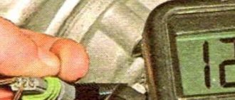
Removing the sensor in three steps
To remove the phase sensor, first turn off the ignition. The sensor connector is easily disconnected - it is held in place by a plastic tab.
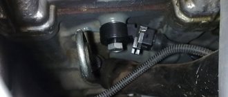
Sensor location and mounting
When the connector is disconnected, use a 10mm socket wrench to unscrew the two bolts holding the sensor in place (see photo). Then the sensor housing is removed from under the casing, pressing it against the cylinder head.
During installation, the tightening force of the fasteners should be 8-10 N*m.
Here we show how the sensor is removed on the 21120 (16v 1.5) engine. For the VAZ-21124 engine, all steps will be the same. If you look at the car connector, you can see three terminals. Their purpose is explained in the drawing.
This is the sensor housing, not the vehicle terminal block
There is a desire to measure the voltage between the two terminals on the right. If you don't turn on the ignition, you'll be fine.
With the ignition on, connect the negative probe to the negative terminal of the battery. Measure the voltage separately on the right and middle contacts - you should get “0” and “+12”.
VAZ-21124 engine control circuit
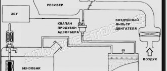
Connection diagram of the VAZ-21124 engine control system with distributed fuel injection under Euro-2 toxicity standards (controller M7.9.7): 1 - ignition coils; 2 — nozzles; 3 - controller; 4 - main relay; 5 - fuse connected to the main relay; 6 — cooling system electric fan relay; 7 - fuse connected to the cooling system electric fan relay; 8 - electric fuel pump relay; 9 - fuse connected to the electric fuel pump relay; 10 — mass flow and air temperature sensor; 11 — throttle position sensor; 12 — coolant temperature sensor; 13 — solenoid valve for purge of the adsorber; 14 — oxygen sensor; 15 — knock sensor; 16 — crankshaft position sensor; 17 — idle speed regulator; 18 — immobilizer control unit; 19 — immobilizer status indicator; 20 - phase sensor; 21 — vehicle speed sensor; 22 — electric fuel pump module with fuel level sensor; 23 — oil pressure warning lamp sensor; 24 — coolant temperature indicator sensor; A - block connected to the wiring harness of the ABS cabin group; B — diagnostic block; B - block connected to the air conditioner wiring harness; G - to the “+” terminal of the battery; D — to the side door wiring harness block; E - block connected to the instrument panel wiring harness; G1, G2 - grounding points; I - the order of conditional numbering of plugs in the block of the immobilizer control unit; II - the order of conditional numbering of contacts in the diagnostic block.
Connection diagram of the VAZ-21124 engine control system with distributed fuel injection under Euro-3 toxicity standards (controller M7.9.7): 1 - ignition coils; 2 — nozzles; 3 - controller; 4 - main relay; 5 - fuse connected to the main relay; 6 — cooling system electric fan relay; 7 - fuse connected to the cooling system electric fan relay; 8 - electric fuel pump relay; 9 - fuse connected to the electric fuel pump relay; 10 — mass flow and air temperature sensor; 11 — rough road sensor; 12 — throttle position sensor; 13 — coolant temperature sensor; 14 — idle speed regulator; 15 — control oxygen sensor; 16 — diagnostic oxygen sensor; 17 — solenoid valve for purge of the adsorber; 18 — knock sensor; 19 — crankshaft position sensor; 20 — immobilizer control unit; 21 — immobilizer status indicator; 22 - phase sensor; 23 — vehicle speed sensor; 24 — electric fuel pump module with fuel level sensor; 25 — oil pressure warning lamp sensor; 26 — coolant temperature indicator sensor; A - block connected to the wiring harness of the ABS cabin group; B — diagnostic block; B - block connected to the air conditioner wiring harness; G - to the “+” terminal of the battery; D — to the side door wiring harness block; E - block connected to the instrument panel wiring harness; G1, G2 - grounding points; I - the order of conditional numbering of plugs in the block of the immobilizer control unit; II - the order of conditional numbering of contacts in the diagnostic block.
Homemade test stand
Below is a diagram that, once assembled, can be tested. It appears that the sensor could have been left on the engine. But not only the electrical part is important, but also the ability to remove and bring up the steel plate.
Test stand
So, taking an E battery (12 Volts) and two voltmeters, we assemble the circuit. Next we run the test:
- On the “free sensor”, the voltmeter V1 will show a voltage of 0.4 V (or less);
- If you install a plate from a transformer in the slot, the voltage will change to 10.8-11.5 V.
Plate dimensions: 20x80x0.5mm or larger. If at “step 1” the voltage was higher than specified, the sensor is faulty. At “step 2”, on the contrary, the value should exceed V2*0.89.
We did not come up with the stand layout, but took it from the information letter. On different VAZ-2112 engines, the phase sensor is checked differently (see photo).
Screenshot of the VAZ “65-2003-I” document
For those who don't understand everything
The rectangle shown in the diagram is a resistor. Resistance is 680 Ohms, power is any. The power source can be not only a battery, but also a 12-volt adapter.
Element E can be an LATR with a rectifier. Then, firstly, try not to exceed the voltage, and secondly, connect the ground (pin 1) to the “ground” tap of the LATR.
The process of replacing a sensor on a 16 valve valve
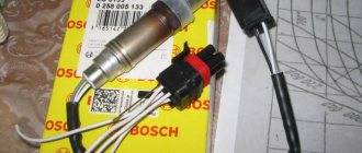
General view of the phase sensor produced by AvtoVAZ
You can change the headlight sensor on a 16-valve VAZ-2112 with your own hands in your garage. The replacement is carried out within 5-6 minutes, but you need to know the exact location of this unit.
The sensor is mounted on the cylinder head, which makes replacing it even easier. Let's consider the sequential process of changing the sensor:
- Disconnect the power supply connector from the sensor.
- Use a socket or a 10-mm open-end wrench to unscrew the sensor.
Using a wrench or a 10mm socket, unscrew the fixing screw - We are dismantling.
We remove the phase sensor from the mounting location - Assembly is carried out in reverse order.
Choice
Selecting a phase sensor for a VAZ-2112 is quite easy. To do this, you only need to know the product catalog number. There are no analogues of the sensor. The car repair manuals indicate that this indicator is called a camshaft position sensor and has article number 2112 - 3706040. Its average cost is 300 rubles .
Causes of malfunction
When the process of replacing and selecting a sensor is considered, it is necessary to determine the reasons why it may fail. So, let's look at the main ones:
- The self-diagnosis mode has failed.
- When starting the engine, when the starter is working and the Check Engine lights up, the car does not see the indicators for 2-3 seconds, and is based on the data provided by the ignition system.
- Fuel consumption increases (consumption standards for the VAZ-2112).
- Acceleration failures and decreased dynamics.
- Stutters when accelerating.
If the phase sensor on the VAZ-2112 malfunctions, the check light comes on and the system displays error P0340 - “Phase sensor error.”
conclusions
Replacing the phase sensor (camshaft position) of the VAZ-2112 16 valves is quite easy. It is much more difficult to determine its malfunction, since there are many indirect reasons, but there is only one direct reason - direct diagnosis. The only thing that will please the car owner is that the part is one of a kind and there are no analogues.
We have a VAZ 2112 car with a 16 valve engine under repair, on which the phase sensor needs to be replaced. We'll show you how to do it yourself quickly and correctly.
The phase sensor is responsible for fuel injection; if it fails, the injectors inject fuel simultaneously, regardless of where the piston and camshafts are located. Symptoms: lumbago, unstable idling, increased fuel consumption, the Check Engine lights up on the instrument panel, and error P0340 is displayed during diagnostics. Before replacing, it is necessary to perform diagnostics, first of all, check all the wires going to the sensor.
The phase sensor is located near the intake camshaft pulley. To replace it, first of all, remove the negative terminal from the battery, then unscrew and move the adsorber tank to the side:
Using a long spanner, crawl over the alternator belt and unscrew the two bolts:
There are no problems with the nearby bolt, just don’t drop it to the bottom. Access to the second one is more difficult; you have to make a lot of movements with the key over a small radius. After removal, inspect the phase sensor for mechanical damage:
If it is damaged, there are scuffs, it is necessary to remove the timing belt cover and eliminate all defects on the drive disk that damage the sensor. In our case, it is intact; its electronic part has failed. To make it easier for us to install a new phase sensor, we use plasticine to fix the far bolt in the hole so that it does not fall:
We tighten everything in the reverse order. Other online instructions for replacing the phase sensor suggest removing the generator, intake manifold, and even headlights and bumper. The article number of the original sensor is 2112.3706040-01; its analogues are VS-CM 0112, CMPS-LA2112, 4102.3847.
The components of the camshaft are elliptical cams, each of which acts on its own personal valve, that is, the task assigned to the camshaft is to control the exhaust and intake valves. Although it is driven by a belt drive from the crankshaft, its speed is half the speed of the crankshaft.
Unfortunately, it is impossible to determine which phase of engine operation is currently in operation only by the position of the crankshaft (the compression stroke with the accompanying ignition of the fuel mixture or the moment of exhaust gas emission), then the camshaft position sensor helps the electronic control unit determine the desired phase gas distribution mechanism. The photo below shows how the camshaft acts on the valve: The camshaft cam (1), rotating, acts on the valve (4) through the pusher (2) and the spring (3), the valve seat (6) opens and the exhaust gas moves through the channel (5). gases/fuel mixture from/to the chambers/combustion chamber (7).
Operation of the gas distribution mechanism
Principle of operation
In the domestic automotive industry, sensors that help the engine control system determine the desired phase of the gas distribution mechanism began to be used in contactless ignition systems of carburetor “eights”. It was installed in a distributor, and its operation was also based on the so-called Hall effect. This sensor removes and transmits to the commutator the signal received from a metal shutter that has one slot, which is attached directly to the crankshaft gear (1).
The relative position of the metal disk and the phase sensor
That is, the curtain itself (2) is constantly located between the magnet and the sensor (3) that reads its signals, thereby preventing it from reading the magnetic lines. The slot (4) serves to generate and supply an impulse from the sensor to the electronic control unit (switch). The presented design is designed in such a way that the phase sensor informs the commutator with a pulse precisely at the moment when the compression stroke occurs in the first cylinder. Pulse parameters: slot opposite - the voltage is almost zero, slot to the side - the voltage is almost equal to the voltage in the on-board circuit.
Sensor differences
The above-described design is called slotted and is used in the control system of a 16-valve engine on a VAZ 2112/2110. On a VAZ 2115, replacing the camshaft sensor is somewhat different, since VAZ engines of the 2111 and 21214 series are equipped with end-type phase sensors. It also works on the principle of the Hall effect, only its design does not use a slot, but a special setting mark. In this case, the pulse passes when the tag approaches the phase sensor. Since the distance between them is much smaller than between the sensor and the camshaft itself, when approaching, the magnetic field of the sensor changes, which contributes to the formation of a synchronizing pulse. On engines of the 2111 series, this mark is located on the camshaft itself, and on the 21214 series - on its drive pulley.
Attention! The pulse formation on the 21214 series engine occurs at the top dead center of the fourth cylinder, which falls on the compression stroke.
Symptoms of a problem
Most often, malfunctions in the camshaft timing sensor occur due to simple contamination of the contacting surfaces and a break in the power circuit, in which case:
- The “CHECK” indicator light is on;
- The engine starts only after prolonged rotation by the starter (about ten revolutions);
- Power drops slightly with a simultaneous increase in fuel consumption (problematic to determine);
- Deterioration in dynamics, dips appear during acceleration.