As we all know, the electric cooling fan on the radiator turns on at a certain temperature, cools the liquid and turns off when it has cooled down enough. It is controlled by a sensor screwed into the radiator, usually in the place where the liquid already leaves the radiator cooled. These sensors are still used in foreign cars to this day. The domestic auto industry, apparently having had enough of problems with this simple element of the cooling system with the transition to electronic injection systems, entrusted the work of turning the cooling fan on and off to the electronic engine control unit, the “brains”. They say this is a complete plus - the controller can be reprogrammed for different on and off temperatures, and most importantly, this very sensor is no longer in the radiator. But the global auto industry continues to install these sensors. Well, okay, we’re talking about Zhiguli cars with a carburetor, and there are still a lot of them.
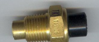
Everyone probably knows what the sensor looks like, but if anyone has forgotten, I stole a photo from the Internet: -
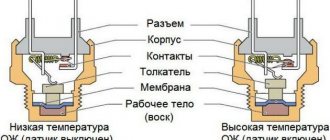
So, the principle of operation of the sensor is simple, it should turn on at a certain temperature, and then turn off, also at a certain, but lower temperature, and so on in a circle. On foreign cars, many people don’t remember these sensors for years, but for some reason it doesn’t work out that way for us. In addition, the manufacturers have added problems to us - on some machines they have simplified the circuit for connecting the sensor to the system - without a unloading relay, that is, the fan is switched directly through the sensor, there is no relay and a rather high current passes through the sensor, by the way, I have exactly such a machine. In the fuse block of such a machine, there is a metal jumper in place of the fan relay; you cannot simply take and install the relay - it will not work, since there are no control contacts (the circuit is simplified). In addition, for different car models, the designers also provide different switching and switching temperatures, but the sensors are all the same in appearance. Let's figure it out.
For a long time, sensors labeled TM108 were on sale, and in general they are still available. They have several options for switching temperature - 92-99 degrees (off/on), these sensors are recommended for front-wheel drive VAZ models and a bunch of other cars - Tavria, Moskvich-2141, Izh-2126. And there is a variant TM-108-10, it has a temperature of 87-92 degrees, it is recommended for the “classics” - VAZ-2103 and beyond. Let me remind you that the VAZ-2101/2102 has a belt-driven cooling system fan that sits on the pump pulley, so there is no need for a sensor there. To put it simply, a “cooler” sensor is recommended for classics. If you have a hot climate, such a sensor can also be installed on a front-wheel drive - the fan will operate earlier, and replacement is not recommended. The operating temperature range is usually stamped on the side of the sensor.
But, these sensors are designed for a maximum load current of 1A, which means they work only through a relay. If there is no relay, then there are two options - you can install the relay yourself (it’s not very difficult and there are diagrams on the Internet), or you can buy a sensor with index 66.3710 or 661.3710. They operate at the same temperatures, but are designed for a maximum current of 16A, which allows them to work directly with the fan - without a relay. Sensor 66.3710 goes to front-wheel drive, and 661.3710 to “classic”. These sensors can be safely used instead of TM108 in circuits where there is a relay, but the other way around is not possible - a sensor designed for a maximum current of 1A quickly fails under direct fan load, sometimes immediately after the first operation. Another motorist, not knowing these nuances, changes several sensors in a row until he finally accidentally comes across the right one, designed for high current (often this is an imported analogue, since after replacing several of ours, a person decides that they are all junk and buys an imported one, with which everything immediately becomes normal) and then curses begin to fall on domestic manufacturers for total defects, although the fault is not defects, but confusion! Often, even salespeople in car dealerships are not aware of these nuances with current, although everyone knows about temperature.
Our main manufacturer of these sensors is Kaluzhsky, it has been producing these sensors for a long time and as it states itself (link to the article “Winter Cherry” from “Behind the Wheel” at the very end) - the defect rate for them is less than 1%, but there are many fakes on the market, I hope that this was relevant at the time of writing this article - 15 years ago, but now there should be fewer fakes, since there is no shortage, and the price of the sensor is not high, there is no point in counterfeiting. But the plant itself also contributes to the confusion; here is a table from the official website:
List of contact relays
If we open the main fuse box of Kalina 2, we will see a set of electrical relay housings. There are no other blocks containing relays in the car. We list the elements used in the “Lux” package (21927/21947):
- K1: radiator fan relay;
- K2: relay switching on door locks;
- K3: additional starter relay;
- K4: additional relay (switches current 50A);
- K6: wiper relay;
- K7: relay that turns on the high beam;
- K8: signal relay;
- K9: relay that turns on the low beam;
- K10: rear window heater relay;
- K11: main ignition relay;
- K12: relay turning on the fuel pump;
- K13: additional relay;
- K14: radiator fan relay 3;
- K15: windshield heater relay 1;
- K16: windshield heater relay 2;
- K17: relay that turns on the air conditioning compressor.
You can compare the layout of elements in “Lux” and in “Norm/Standard”:
Let's consider the data relevant for the “Normal/Standard” configurations:
- K1-K12: as above;
- K13: radiator fan relay 3;
- K14: windshield heater relay 1;
- K15: windshield heater relay 2;
- K16: air conditioning compressor relay.
The last list is also relevant for Kalina Cross Norma. And in more expensive trim levels of the crossover, the “Lux” scheme will probably be used.
Tips for motorists
The radiator fan of the engine cooling system of the Lada Kalina passenger car should turn on automatically when the coolant temperature reaches more than 95 degrees. And if this does not happen, then the engine begins to overheat and the driver’s failure to take timely measures to reduce the temperature (switching to idle speed) leads to jamming of the pistons in the engine cylinders.
to start troubleshooting a fan failure by checking the integrity of the fuse that protects this electrical circuit. It is located on the side of the console near the front passenger's feet. To get to it, you need to unscrew one screw securing the cover with deflectors designed to supply warm air to the passenger’s feet.
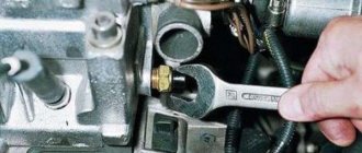
But you can remove the additional fuse and relay block only after you unscrew the bolt securing it, for which you will need a 10mm wrench. You need to take it out carefully and slowly so as not to damage it, since the bundle of wires suitable for it is very in the way . There is only one fuse in the block, exactly the one you need.
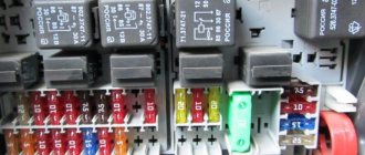
If the fuse is intact, then you can immediately check the serviceability of the relays through which voltage is supplied to the fan motor. There are two of these relays: the leftmost one above the mounting bar is designed to turn on a low fan speed, and the rightmost one is designed to turn on a high fan speed.
Another malfunction associated with the fan relay is that the fan continues to operate after the ignition is turned off, and if you leave the car in the parking lot without paying attention to it, the battery will discharge, which will lead to problems with starting the Kalina engine. Sticking of the relay contacts occurs due to antifreeze entering this block as a result of its leakage from the heater radiator.
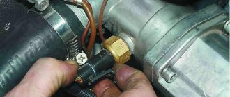
If everything is in order with the fuse and relay, then you will have to open the hood and check the serviceability of the temperature sensor, which commands the fan to turn on. It is located on the right radiator tank. To check its functionality, simply remove the plug connector from it and close the connector terminals with a jumper. If the fan starts working, then the sensor is working, and if it doesn’t work, then before drawing a conclusion that the sensor is faulty, you need to check the serviceability of the fan motor itself. To do this, you will need to connect the motor terminals directly to the battery terminals.
Checking and replacing the Kalina cooling fan resistor
Removing the additional fan resistor is done as follows:
- put the car on the “handbrake”;
- open the hood;
- remove the ground wire from the battery;
- remove the engine splash guard;
- unscrew and remove the engine crankcase protection (if installed);
- press the block latch and unplug the electric fan power supply wiring harness;
- Using a Phillips screwdriver, unscrew the two screws holding the additional resistor;
- move aside the resistor mounting bracket together with the block;
- pull out the resistor.
Checking the resistor consists of two stages:
- visual inspection of the integrity of the spiral;
- checking the resistor winding for open circuit using an ohmmeter.
If a winding malfunction is detected, the resistor must be replaced with a new one. If the thermal fuse is faulty, then all you can do is replace it. To do this, you will need a soldering iron to remove the burnt fuse and solder a new one in its place. All that remains is to put the parts in their original places. Installation of the Kalina cooling fan resistor is carried out strictly in the reverse order of removal.
DIY fault repair
We will not talk about solving problems such as failure of fuses or the sensor itself. Everything is so simple here - failed elements are removed from their installation locations and replaced with new ones.
Separately, it is necessary to highlight the replacement of the ventilation unit - read about this below:
- So that during the repair process you do not have to dismantle the radiator, do everything carefully, since there is a possibility of damage to other elements.
- Open the hood and disconnect the battery. Remove the air filter.
- Having done this, you can dismantle the radiator grille.
- Next, you will need to unscrew the top mountings of the optics - the right and left lights.
- Using a 10mm wrench (it will be more convenient to take a socket wrench), you will need to remove the upper front panel.
- After these steps are completed, you will need to disconnect the plugs that are connected to the ventilation unit. Having done this, the wires can be twisted a little.
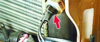
- Next, using a wrench, you will need to unscrew the four screws that secure the device to be replaced. The arrows in the photo indicate the screws that secure the assembly; they will need to be unscrewed.
- Only after the unit is freed will it be necessary to dismantle it and replace it with a new one. After removal, just in case, clean the connectors themselves so that in the future you will not be bothered by the problem of poor contact. Further assembly of the system and installation of all elements is carried out in the reverse order.
Removing the fan sensor
DVV is a non-separable product and cannot be repaired. However, to ensure that it is fully operational, it must be removed from the vehicle. To do this proceed as follows:
- The car is placed on level ground with the handbrake lever raised.
- Start working after the engine has completely cooled down, removing the terminals from the battery.
- Having squeezed out the plastic clip, remove the chip with the cable from the DVV glass.
- Remove the plug from the expansion tank, otherwise when the sensor is removed, a small amount of antifreeze will splash out.
- Use a spanner wrench or a 19 DVV socket to unscrew it from the seat. If the thread does not lend itself well, then apply WD 40 lubricant under the sensor nut (you can buy it at any auto store or gas station).
Removing the chip from the sensor:
How to check the sensor yourself?
Checking the fan switch sensor is not difficult.
- If there is a need to diagnose it, you must first find out its functions and operating principle.
- After this, you can test the system by heating the most vulnerable part of the sensor housing. To do this, you need to remove it from the radiator, carefully inspect it, check the contact pads, inspect the wires, and, if necessary, clean it.
- Next, you will need a tool that you can make yourself from a regular light bulb and battery, or use a special tester.
- Bring water to a boil, then connect the tester and sensor contacts and lower its vulnerable side into the water.
- After this, a short circuit should occur. This action will cause the lamp to ignite, or the characteristic sound signal of the tester to appear. If the device shows that the contacts closed before colliding with boiling water, then the sensor is undoubtedly faulty. The author of the video, Mechanical Technician, will tell you how to check the fan switch sensor.
How to find the reason
Let's start by checking the electric motor. Disconnect the electrical wires and connect directly to the battery, observing the polarity. If the fan doesn't start, that's the problem. If it works, you need to look for another reason.
Check all contacts on the connectors, as well as behind the relay and fuse. They are located in an additional mounting block, which is located on the right side of the instrument panel next to the lower heater duct.
The fuse (50A) can be checked with a tester; it is better to take a working relay and install it in the appropriate socket. If the problem is not resolved, continue.
Check temperature sensor. Warm up the engine to operating temperature, stop the engine and disconnect the sensor. It is located on the top of the thermostat housing. When the sensor is disabled, the controller must independently start the fan for continuous operation.
Start the engine and wait until the fan starts. If the coolant temperature has reached a critical temperature and the fan does not turn on, look for a broken wiring.
Do I need to change the fan?
If you determine that the problem is in the fan itself, or more precisely in its motor, you can try to fix it. Most often it stops working due to broken brushes or problems with the rotor bearings. The commutator or winding crack is rarely damaged.
If the fan cannot be repaired, it must be replaced.
Under no circumstances should you drive a vehicle with the fan not working. Overheating of the engine inevitably leads to the destruction of rubber hoses of the cooling system, seals, and can also cause failure of the piston group elements.
General information
On Priora and Kalina there is a fan that acts as the main cooling system. It is necessary to prevent overheating and ensure stable operation of the internal combustion engine (ICE). The main element for cooling the power unit is the sensor. Using its signal, the fan is activated.
In cars, this unit is triggered in cases where the thermal performance of the engine exceeds the norm. After starting the fan, which is located near the engine and is triggered by a signal from the controller, the temperature of the internal combustion engine drops to an acceptable level.
Important! The ventilation device does not turn on in cases where the sensor does not produce a signal. This leads to overheating of the engine.
Installing a new fan sensor
After dismantling the old device, a new DVV is installed:
- The sensor is inserted into the mounting socket, having previously lubricated the threads of the device skirt with oil.
- Screw in the meter with a spanner wrench or a 19mm socket without applying excessive force.
- The cable block is inserted into the glass of the new sensor.
- After unscrewing the radiator cap, pour antifreeze into its neck until the fluid level in the expansion tank is between o and “Max”.
- The radiator cap and expansion tank plug are returned to their place.
- Start the engine and wait until the arrow on the instrument panel approaches the red zone. If the fan turns on at this moment, this means that the repair was completed correctly.
Experts advise purchasing a new coolant temperature sensor only from a brand model. Savings when buying a cheap product can result in exorbitant financial costs for engine overhauls.
At the first overheating of the Kalina engine, you need to stop and stop driving to allow the engine to cool. If the problem is a breakdown of the engine, then you need to get home, making stops and watching the coolant temperature arrow along the way. To avoid this, remove the fan motor cable and directly connect the fan with additional wires to the battery. This way you can return to the garage without letting the coolant boil.
Repair or replacement
If the reason for the impeller not rotating is the electric fan, you can try to repair it. Often, repairs come down to replacing the brushes and bearings of the electric motor. But if a short circuit occurs in the stator or rotor windings, repair is impractical and the unit will have to be replaced. There is nothing else to break in the electric fan, since the design is simple.
If forced cooling does not work, the vehicle cannot be operated. Overheating of the coolant is dangerous for all components of the power unit. The rubber connecting hoses and cylinder head gasket begin to deteriorate and the valves burn out. Ultimately, extremely high temperatures will cause the pistons to expand and the cylinders to scuff, meaning a major engine overhaul will be required.
Video “How to properly replace the thermostat on a Lada Kalina?”
If the problem of a non-functioning sensor in a Lada Kalina car lies in the failure of the thermostat, then this unit will also need to be replaced; detailed instructions for replacing it at home are presented below (the author of the video is Alexey Golubkov).
Why doesn't the cooling fan turn on on Kalina? Several reasons to choose from
Within the city limits this is not so serious: if you are in a hurry, you can leave the car and get where you need to go by public transport in order to deal with the cooling system later. But between cities, a non-working fan is a great headache. If you don’t find the cause and don’t eliminate it, it can take 8 hours to drive 40 kilometers without a tow: you drive 2-3 km, then you stop and wait for it to cool down. It's going to be a fun trip! Especially if there are tired children behind you who were planning to quickly get there and start resting.
Why doesn't the cooling fan turn on on Kalina?
There are several reasons for this. Some can be fixed on site, while others will require additional spare parts. But even if you can’t start the fan right away, you can at least assess the prospects and start waving the cable as it passes a couple of hours earlier, while you still have the strength to do something.
Before checking the remaining components of the cooling system, you need to make sure that the worst has not happened to you, and. I must say that in Kalina this is an extremely unreliable unit and for some reason it breaks down often and frequently. There are cases when it stopped working, even if it was changed the day before yesterday. Therefore, many experienced owners of this car, when going on a long trip, take a spare one with them. Yes, just in case!
You can make sure that the thermostat is normal (or not) by touching the lower radiator pipe. If it remains cold, it means that the thermostat is no longer alive, and you need to get a backup one or ask for a tow. In the absence of both fellow travelers and supplies, you will have to crawl slowly and sadly to the nearest service station.
Having excluded the thermostat from the list of probabilities, we check the electrical circuit. First - fuses
(how to check them correctly,).
The first is the one that is directly responsible for the electric fan. It is located on the side of the console, where the front passenger's feet are. It’s not difficult to get to it: unscrew the screw that secures the cover with deflectors for blowing warm air - and in front of you is the required spare part.
If this fuse is intact
, you will have to climb further into the additional block. Use a ten key to unscrew the fastening bolt and pull out the entire assembly. At this stage, you need to be patient and careful: extraction is significantly hampered by a whole bunch of wires going to the block. If you pull one out, you will be stuck on the highway for a long time. But it doesn’t take long to look for a fuse in the block: there is only one there, exactly the one you need.
If this part is normal, we immediately check the relays - they are located in the same block and transmit voltage to the fan motor. There are 2 of them: located above the mounting strip on the left edge is responsible for the operation of the fan at low speeds, the one on the far right turns on its high speed. Both must be in working order.
If no faults are found here, you will have to crawl under the hood.
You need to check both it and the temperature sensor. Let's take a look at the electric fan first. To ensure that the engine is working, its terminals are connected directly to the battery. If it starts, it means everything is fine with the fan. Let's move on to the sensor. Depending on what engine is on your iron horse, the actions will be different:
With carburetor:
We remove the plug connector of the temperature sensor (it is located, by the way, on the right radiator tank) and close its terminals with a jumper. The fan started spinning - the sensor is working, the terminals just came off. Left dead - it's time to change the sensor; With injector
We look for the sensor next to the thermostat and remove the connector from it. If the fan starts spinning, it means that the emergency mode has turned on, and your sensor has already burned out.
Owners of popular Lada Kalina models often encounter situations when the cooling fan does not turn on. This situation forces the driver to periodically stop to allow the engine to cool down. If a malfunction occurs in frosty weather, then it has almost no effect on the functionality of the system, but in warm periods it significantly prevents the LADA Kalina from moving smoothly.
Most Lada Kalina owners are not able to independently diagnose the reasons why the cooling fan does not turn on, much less eliminate them. Tow trucks and services, as well as a switching diagram, are happy to come to their aid.
see also
Comments 47
People, help me, my fan doesn’t turn on, I thought it was the sensor, but no, it still doesn’t turn on, but when you remove the connector from the sensor, it turns on, and if you put it back on, it doesn’t turn off, what should I do, and maybe it’s because of the cap on the expansion valve of the Priora I have?
Could be a relay or fuse
What specific wire is this?
problem solved! I changed the wire to ground and everything worked)) thank you all so much, friends!
Clean and check regularly - the effect will not last long! neither nail nor rod!
problem solved! I changed the wire to ground and everything worked)) thank you all so much, friends!
Don’t be stingy and install an on-board engine, there are a lot of benefits from it and you can set the Carlson switch-on temperature and reset errors and a lot of other things...
And the bad mass is to blame. I also crawled and changed... After changing the mass, the side panel and the tidy show a difference of a couple of degrees between themselves
The main reasons why the radiator cooling fan does not work
Let's look at the main options and places to look for faults:
- Thermostat.
If it fails, this is the reason why the cooling fan does not work correctly. To diagnose this malfunction, you should touch the lower pipe. If it is cold, then the thermostat is dead. Many Kalina car owners are accustomed to this phenomenon, since it often breaks down, and they carry a spare one with them.
- If it's not the thermostat, then the next step is the fuses. You need to make sure that they are working and all controllers too. The easiest way is to test them using a tester or ohmmeter. The fuse diagram is here.
If the fuse is alive, then you will have to remove the additional fan control unit. To do this, it is worth moving the warm air duct and using a 10 mm wrench to unscrew the fastenings of the unit. Now you can get it freely. It has two relays that are responsible for turning on the fan and for high speeds. Let's diagnose both.
- Now, we can move on to the darkest option - we climb under the hood and “ring” the contact wires of the fan itself. Of course, there may be a break or break in the wire, but there is nothing worse than a burnt winding inside the fan. Most likely the fan in this case will need to be replaced.
- Another reason for the fan not turning on may be a broken thermostat sensor. In order for the fan to start in emergency mode, you will have to remove the connectors from it. You can check the sensor by removing the thermostat and placing it in a pan of hot water; the thermostat should open.
- The last reason why the fan may not work is a break in the switching circuit itself.
Block in the engine compartment
The power fuse box is located in the engine compartment under the hood, near the left strut support. To get to it, you need to open the lid by prying the latch.
1 (30 A) - engine control system circuit . If there are problems with the electronic control unit, short circuits or other malfunctions, this fuse may blow out.
2 (30 A) - vehicle on-board circuit . 3 (40 A) - vehicle on-board circuit .
4 (60 A) - generator circuit.
5 (50 A) - electric power steering circuit.
6 (60 A) - generator circuit.
In case of any problems, it is important not to panic, to think soberly and logically. The most important thing is to diagnose and establish the cause of the breakdown. If you don’t have enough experience or nerves, it’s easier to sign up at the nearest car service center if it has a competent electrician.
I hope this article will help you deal with electrical problems and quickly fix any Priora malfunctions. If you have any experience or information, please leave a comment below, useful information will be added to the article.
Design of the LADA Kalina cooling system
Cooling system: 1 — expansion tank;
2 — radiator outlet hose; 3 - inlet hose; 4 - radiator; 5 — steam exhaust hose; b — radiator supply hose; 7 — electric fan; 8 — electric fan casing; 9 — coolant temperature sensor; 10 — coolant temperature indicator sensor; 11 — throttle assembly; 12 — bracket for the coolant pump pipe; 13 — coolant pump; 14 — coolant pump pipe; 15 — heater radiator supply hose; 16 — heater radiator outlet hose; 17 — exhaust pipe; 18 — coolant pump pipe hose; 19 — thermostat housing Expansion tank. Coolant is poured into the system through the expansion tank. It is made of translucent polyethylene, which allows you to visually monitor the liquid level. To do this, the marks “MAX” and “MIN” are marked on the wall of the tank. In the upper part of the tank there is a pipe for connecting to the radiator steam exhaust hose, in the lower part there is a pipe for connecting to the inlet hose. Expansion tank viburnum
Expansion tank cap with valves. The tightness of the system is ensured by the inlet and outlet valves in the expansion tank cap. The exhaust valve maintains increased (compared to atmospheric) pressure in the system on a hot engine (due to this, the boiling point of the liquid becomes higher, steam losses are reduced}. It begins to open at a pressure of at least 1.1 bar. The intake valve opens when the pressure drops to system relative to atmospheric pressure by 0.03-0.13 bar (on a cooling engine).Expansion tank cap with valves
The coolant pump is a vane, centrifugal type, driven from the crankshaft pulley by a timing belt. The pump housing is aluminum. The roller rotates in a double-row bearing. The bearing is lubricated for its entire service life. The outer ring of the bearing is locked with a screw. A toothed pulley is pressed onto the front end of the roller, and an impeller is pressed onto the rear end. A thrust ring made of a graphite-containing composition is pressed to the end of the impeller, behind which there is an oil seal. The pump housing has a control hole to detect fluid leakage when the pump fails. It is recommended to replace the pump as an assembly. The redistribution of liquid flows is controlled by a thermostat. Coolant pump Kalina
The cooling system consists of two so-called circulation circles:
- The movement of liquid through the cooling jacket and radiator forms a large circulation circle.
- The movement of liquid through the engine cooling jacket, bypassing the radiator, is a small circle of circulation.
The cooling system also includes a heater radiator and a throttle body heating unit. Liquid circulates through them constantly and does not depend on the position of the thermostat valves.
Thermostat. It has a solid temperature-sensitive element and two valves that redistribute the flow of coolant. On a cold engine, the main thermostat valve blocks the flow of fluid from the radiator and the fluid circulates only in a small circle, bypassing the radiator. At a temperature of (85±2) °C, the thermostat valves begin to move, allowing liquid flow into the radiator and closing the bypass channel. At a temperature of about (100±2) °C, the main valve opens completely and the bypass valve closes. Almost all the fluid circulates in a large circle through the engine radiator. Thermostat viburnum
Coolant temperature sensor. To monitor the coolant temperature, a sensor is screwed into the engine cylinder head, connected to the temperature indicator in the instrument cluster. In the outlet pipe, next to the thermostat housing, there is a coolant temperature sensor that provides information to the controller. Coolant temperature sensor viburnum
The heater radiator is built into the engine cooling system and is designed to heat the passenger compartment by circulating hot coolant through it.
The radiator consists of two vertical plastic tanks (the left one is with
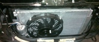
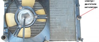
baffle) and two horizontal rows of round aluminum tubes passing through the cooling plates. The tubes are connected to the tanks through a rubber gasket. The liquid is supplied through the upper pipe and discharged through the lower. Next to the inlet pipe there is a thin pipe for the steam removal hose. The radiator has a casing with an electric fan. There is a drain plug at the bottom of the right tank. radiator viburnum The fan maintains the thermal operating mode of the engine and is switched on via a relay based on a signal from the controller.
Modernization of Kalina SOD
The main problem of the Kalina cooling system is the formation of air locks. Today there are a number of effective ways to eliminate this defect. The reason lies in the design features of the SOD. The operation of the cooling system is based on the interconnected functioning of many parts. The use of the large and small circuits depends on the temperature of the antifreeze circulating through the system. The normal operation of the entire power plant depends on this.
You can modify the cooling system yourself or at a service center. Professionals rarely engage in all sorts of modifications, recommending replacing or repairing a particular component. This method may be more expensive, but not always more effective.
Classic ways of improvement
In order to solve the problem with the formation of air locks, you need to remove the expansion tank cap and start the engine. Then wait until the coolant temperature rises to the critical red zone until forced cooling by the fan comes into operation. After this, you need to press the gas pedal several times and turn off the engine.
If the method is ineffective, there is another method. To do this, you need to dismantle the engine protection, loosen the clamp and remove one of the tubes of the throttle body heating fitting. Then unscrew the cap of the expansion tank and, applying a rag, start blowing into it until antifreeze begins to flow from the removed pipe. In order to modify the standard cooling system, many car owners install a more efficient 6-hole thermostat, install a coolant filter and another heater faucet.
To increase circulation efficiency, an additional pump is often installed.
Other upgrade options
If the car is equipped with an electronic gas pedal, the hose that previously went to heat the throttle assembly is now looped into the cooling system. To prevent the formation of air pockets, an additional pipe with a smaller diameter is used, which is installed instead of the above hose. The hose for the air duct is placed near the thermostat; for this, a tee is used, mounted in the pipe fitting to the radiator. The second end of the pipe is connected to the steam removal hose near the expansion tank (you will need another tee).
The modification ensures a stable operating temperature of 90 degrees in urban conditions, and the stove begins to warm up at 50 degrees.
The next improvement method is to equip the steam outlet with a special hydraulic fence. To do this, a tube from a dropper is mounted in the steam removal hose, which is immersed in antifreeze at the bottom of the expansion tank. As it cools, the antifreeze is drawn into the outlet pipe, which prevents air from the cooling system. If desired, you can combine both methods.
Forced fan activation
One of the shortcomings of the cooling system of the Lada Kalina is the late activation of the electric fan. Any car owner, even with minimal car repair and maintenance skills, can solve this problem if desired. On most internal combustion engines, the operating temperature should be maintained at 90-95 degrees. On Kalina, the forced cooling fan turns on at a temperature of 100 or 105 degrees. That is, intensive cooling begins at the moment when the engine has already begun to overheat, and this negatively affects the service life of the power unit. To solve this problem, you can install a button to turn on the fan in the cabin, which, when pressed, starts cooling at any time. To work you will need the following parts:
- connection terminals;
- 4-pin relay with mounting bracket;
- contact blocks for connecting the button and relay;
- wire with a cross-section of at least 0.75 mm.
Connecting the forced (manual) mode of fan operation is carried out according to the following scheme:
- On the button connection block, all unnecessary wires are cut off, leaving only two in the center for illumination and two on the edge for connection.
- Now you should connect the relay and button. On the passenger side, the protective trim of the center console is removed; there are several relays there. To find out which one is needed, you should start the engine and disconnect the wire block one by one from the temperature sensor on the thermostat.
- In this case, the fan should work; now you need to disconnect the relay. If after disconnecting one or another relay the fan stops, then this relay is responsible for turning on forced cooling. If the car stalls when the relay is removed, it means that it is responsible for the fuel pump; you should replace it and start the engine again.
- Now you should find the pink and white wires, strip their ends and twist them together, the connection is insulated.
- The relay wires are connected to the prepared wire block. White - to contact 87, pink - to 85, contact 86 is connected to the power button, contact 30 is assigned to ground. After completing the connection, all that remains is to find a place to secure it, for example, under a dashboard.
- All that remains is to connect the button. The two remaining wires are connected to any backlight lamp, which lights up when the ignition is turned on.
The modification allows you to turn on the cooling fan on the Lada Kalina at any time, not only while the engine is running, but also when it is turned off.
Any modernization can be done with your own hands; it is not at all difficult if you follow the step-by-step instructions. For normal operation of the cooling system, all components and elements must work properly. The fan, although simple in design, is important; without it, you can end up with a major engine overhaul. For this reason, you need to carefully monitor the performance of all components and, if malfunctions are identified, fix them immediately.
Main reasons
- Coolant temperature sensor malfunction. There are two of them on the Lada Kalina. One provides data to the instrument panel, the second to the car's ECU.
- The fuse in the fan circuit has blown.
- Motor malfunction.
- Lost contact in electrical wiring connectors.
Verification algorithm
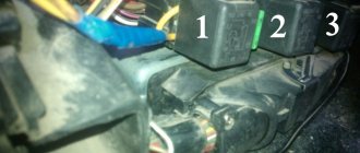
- Disconnect the connector from the temperature sensor, which is located near the thermostat. When the sensor is disconnected and the ignition is on, the cooling fan should run constantly. If the fan does not turn on, it may be the fan fuse or the fan itself.
- The fan relay and fuse box on the Lada Kalina is located under the decorative trim near the left foot of the front passenger. The block consists of three relays, two of which (1 and 3) are responsible for operating the fan at high and low speed. There is a fuse nearby. The fuse is checked visually (the integrity of the fusible link) or with an ohmmeter, which should show zero resistance. The relay can be checked by connecting the device to the terminals of the contact group and applying voltage from the battery to the switching terminals. You should not install a “bug” made of wire instead of a blown fuse. Fires in cars are not uncommon. It is necessary to find the cause of the burnout; perhaps a short circuit in the electric motor or wiring. Install a similar fuse. If everything works fine, then everything is put back in place; if the fuse blows again, then the reason is a short circuit. The fuse rating is 50 A.
- The serviceability of the fan itself is checked by applying voltage from the battery directly to its connector. If it rotates and all other elements are working properly, then the only reason is the electrical wiring. Fortunately, this is quite rare. When the engine does not work even when directly connected to the battery, there is only one way out - replacing the fan. Repairing the engine does not make sense, since the cost of a new one is not that high, and the reliability of the repaired one is unlikely to be high.
Sensor check
For a complete check, the sensor will have to be removed, which involves draining a small amount of coolant.
You can check the sensor with a tester in resistance mode. The probes of the device are connected to the connector terminals and the tip of the sensor is immersed in hot water. Table of indications.
| Temperature (°C) | Resistance (Ohm) |
| 100 | 177 |
| 90 | 241 |
| 80 | 332 |
| 70 | 467 |
| 60 | 667 |
| 50 | 973 |
| 45 | 1188 |
| 40 | 1459 |
| 35 | 1802 |
When checking, you need to check the condition of the connector contacts. If the contact is poor, they will overheat and the contact will weaken even more, until it completely disappears. Connectors must be dry, clean and free from overheating.
Let's sum it up
If a cooling circuit fan in a Lada Kalina fails to operate, then such a malfunction can be corrected independently. We have reviewed almost the entire list of reasons that could cause a malfunction, and also provided an algorithm for replacing the unit. Use our material as instructions for action and tend to periodically inspect the cooling system; a switching diagram can also help you. This will minimize the risk of unpleasant circumstances occurring on the road.
Replacing the cooling fan Lada Kalina
To replace the cooling fan, it is not necessary to go to a service station. You can do this without much difficulty on your own.
Required tools:
- head with ratchet or socket wrench 10;
- spanner or open-end wrench 8;
- screwdriver with Phillips bit;
- pliers.
Work order
- Place the car on a level surface.
- Raise the hood, disconnect the ground wire from the battery.
- Using a 10mm wrench, unscrew the two air filter mounting bolts.
- Disconnect the mass air flow sensor connector by pressing the latch.
- Disconnect the purge valve connector located on the air filter housing.
- Using a screwdriver, unscrew the bolt of the air duct fixation clamp and remove the corrugation.
- Unscrew the 4 screws securing the air filter cover.
- Remove the cover and remove the filter element.
- Using a size 8 wrench, unscrew the nut securing the air intake and remove it.
- Using a size 10 wrench, unscrew the two nuts securing the fan casing on the right in the direction of travel of the car, and then with a size 8 wrench, unscrew the two nuts on the left.
- Disconnect the fan power connector.
- Carefully, so as not to damage the radiator fins, remove the fan along with the housing.
- Using a 10mm wrench, unscrew the 3 bolts securing the electric motor and remove it from the housing.
- Install a new electric motor with impeller in its place.
- Screw the casing assembly with the fan to the radiator.
- Connect its connector.
- Carry out the rest of the installation work in reverse order.
Step-by-step instructions for replacing the coolant temperature sensor on a Priora
If for some reason you cannot contact specialists for service, then you can do the work yourself.
- Allow the power plant to cool to an acceptable temperature.
- Prepare any rags.
- Remove the housing from the air filter. A shaped screwdriver will come in handy in this case.
- Carefully loosen the clamp and remove the air duct.
- At this stage, disconnect the harness and remove the rubber pads directly from the body.
- Remove the connector from the sensor.
- Now place the prepared rags on the clutch cover and under it.
- As quickly as possible, using a key set to “19”, unscrew the broken sensor and install a new one. Tighten everything as best as possible.
- Do not unscrew the coolant reservoir cap before the replacement procedure. In this case, losses of OX will be minimal.
- Now you can put everything back together in reverse order.
- Check the coolant level.
- Start the engine.
- When the fan works and everything works as expected, without interruptions or leaks, the work is considered completely completed.
We invite you to watch the video on replacing the sensor on a Priora.
Vehicle maintenance
A catalog of consumable spare parts required for maintenance is given in Chapter 3b of this manual.
Periodic Maintenance
Timely and regular maintenance of the car in accordance with the technological map (see the service book attached to the car upon sale) can significantly extend the life of the car.
A message appears in the notification center indicating the mileage remaining until the next service. This message appears and remains for 4 seconds each time the ignition switch is turned to position 2.
The display begins to show mileage - 10,000 km. This distance gradually decreases (every 50 km) until zero remains (in this case, service must be performed). After each service the display is reset again to 10,000 km.
Note
Service intervals are based on 50 km intervals, so short journeys may not be shown on the display.
The vehicle must be serviced every 10,000 km or every 6 months (whichever comes first).
Note
If service has not been performed (or the display has not been reset), the distance indicator will remain at that value after reaching zero until reset.
The service center employee must make the appropriate notes, stamp and sign the vehicle’s service book for each maintenance service.
Replacing brake fluid
Brake fluid requires replacement every two years, regardless of the vehicle's mileage.
Note
Replacing brake fluid is included in scheduled maintenance and is paid for.
Coolant replacement
Engine coolant must be replaced every three years, regardless of the vehicle's mileage.
Note
Coolant replacement is included in scheduled maintenance and is paid for.
Monitoring the content of harmful emissions in exhaust gases
This vehicle is equipped with a system to control harmful emissions and fuel vapors. Incorrect engine settings can affect exhaust emissions, engine performance and fuel consumption, and can cause elevated temperatures that damage the catalytic converters and engine.
Attention Please be aware that replacement, modification or counterfeiting of these devices is punishable by law. In addition, outside interference in engine settings is strictly PROHIBITED!
Checking the functionality of the sensor
Checking the functionality of the device should begin with monitoring the response temperature. To do this you will need a thermometer and a multimeter. All actions can be performed independently, without resorting to a visit to the service center. If the multimeter is equipped with a thermocouple, then there is no need for a thermometer. To check the sensor, follow the instructions below:
- Switch the multimeter to resistance measurement mode. For convenience, you can select the dialing mode;
- Immerse the threaded part of the sensor in water;
- Start gradually heating the water. You can control the temperature using a thermometer, or temporarily switching the multimeter to the thermocouple mode;
- Wait for the device to respond;
If there is a critical deviation of the response limit, the sensor must be replaced. After purchasing a new device, you must check its suitability. Defective products are very common on sale, so checking whether the sensor turns on correctly is the responsibility of every car owner.
What is clearance and how important is it?
This value shows the possible deviation of a given series from the specified nominal value. A correctly calculated circuit must take this indicator into account, or appropriate adjustments are made after assembly. As you understand, our friends from the Celestial Empire do not bother themselves with this, which has a positive effect on the cost of their goods.
The result of such a policy was shown in Figure 4; the part works for some time until the limit of its safety margin is reached.
- We make a decision by comparing the readings of the multimeter with the nominal value; if the discrepancy goes beyond the error limits, the part definitely needs to be replaced.
Design, principle of operation
The design of this sensor includes a thermistor - a resistor that changes resistance depending on the temperature surrounding it. This thermistor is placed in a metal case with a thread applied to it. A tail section made of plastic is connected to this body. This part contains contacts for connecting wiring. One contact is positive and it comes from the electronic unit, the second is negative and it is connected to ground.
In order for the thermistor to work, a voltage of 5 V is constantly applied to it. This voltage is supplied to it by the electronic unit through a resistor having a constant resistance. Since the coolant temperature sensor thermistor has a negative temperature coefficient, as the temperature increases, its resistance will decrease, and the voltage supplied to it will also decrease. Based on the drop in this voltage, the electronic unit calculates the engine temperature and also displays its value on the dashboard.
The exact installation location of this temperature sensor differs from car to car, but only slightly. It can be installed in the cylinder head near the thermostat housing, or on the thermostat housing itself. It must be located near the outlet pipe through which the liquid flows into the radiator. It is located near this pipe in order to transmit accurate temperature data.
Problems when paying with bank cards
Sometimes difficulties may arise when paying with Visa/MasterCard bank cards. The most common of them:
- There is a restriction on the card for paying for online purchases
- A plastic card is not intended for making payments online.
- The plastic card is not activated for making payments online.
- There are not enough funds on the plastic card.
In order to solve these problems, you need to call or write to the technical support of the bank where you are served. Bank specialists will help you resolve them and make payments.
That's basically it. The entire process of paying for a book in PDF format on car repair on our website takes 1-2 minutes.
Signs of sensor malfunction
This sensor is considered to be very reliable due to its comparative simplicity of design. However, there may be problems with it too. Usually they come down to a violation of the calibration, which leads to a violation of the resistance and, as a result, incorrect operation of the electronic unit, since it performs part of its functions based on the engine temperature.
One of the most obvious signs of failure of this sensor is the failure of the fan to turn on when the temperature exceeds the set value. But this indicator will not be reliable if there are two sensors - the main one, for transmitting the temperature value to the electronic unit, and the additional one, responsible for turning on the fan. In this case, failure to turn on the fan will indicate damage, oxidation of the wiring, or failure of the sensor responsible for its operation.
General diagram of VAZ-1117, VAZ-1118, VAZ-1119
1 — right headlight; 2 — engine compartment lamp switch; 3 — sound signal, 4 — Lada Kalina starter; 5 - battery; 6 - generator; 7 — windshield wiper electric motor; 8 — left headlight; 9 — power window switch of the right front door (passenger); 10 — power window motor of the right front door; 11 — right front door lock; 12 — connection block to the right front column; 13 — windshield washer motor; 14 — air temperature sensor; 15 — connection block to the injection system wiring harness; 16 — left front door lock; 17 — brake fluid level sensor; 18 — connection block to the left front column; 19 — right front door power window switch (driver); 20 — left front door power window switch; 21 — door lock switch in the switch block; 22 — electric window motor of the right front door; 23 — mounting block; 24 — immobilizer; 25 — power accessories control unit; 26 — instrument cluster; 27 — right side turn signal; 28 — glove compartment lighting lamp ; 29 — glove compartment lamp switch; 30 — brake light switch; 31 — ignition switch; 32 — lighting control module; 33 — steering column switch; 34 — left side direction indicator; 35 — connection block to the right rear column; 36 — rear door lock; 37 — rear window heating switch; 38 — reverse lock switch; 39 — alarm switch; 40 — heater motor switch; 41 - additional resistor; 42 — heater electric motor; 43 — block is connected to the left rear column; 44 — electric fuel pump with fuel level sensor; 45 — reverse lamp switch; 46 — handbrake sensor; 47 — cigarette lighter; 48 — reverse lock; 49 — connection block to the radio device; 50 — backlight lamps for heater control levers; 51 — Kalina illuminator; 52 — control unit for electromechanical power steering; 53 — interior lighting unit; 54 — right rear light; 55 — trunk locking motor; 56 — switch in the trunk lock; 57 — license plate lights; 58 - additional brake signal; 59 — rear window heating element; 60 — trunk lighting; 61 - left rear light
Elements of the instrument panel harness connection diagram
1, 3, 4, 5 — blocks of the tidy wire bundle to the front harness; 2, 8 - the same for the rear “pigtail” of wires; 6, 7, 9, 10 - continuation of the direction to the assembly unit; 11 — power supply for the lighting control device; 12 — set of instruments; 13 — toggle switch for the electric motor of the stove; 14 — power supply to the air supply box; 15 — ignition switch Lada Kalina; 16 — immobilizer block; 17 — block of the dashboard wiring harness to the ignition system wire bundle; 18 — cigarette lighter power supply; 19 — alarm switch; 20 — rear window heating switch; 21 — brake light switch; 22 — alarm light breaker; 23 — adjustment of computer modes; 24 — windshield wiper control; 25 — VAZ horn switch; 26, 27 — heating and ventilation control lighting lamps; 28 — glove box lighting; 29 — power supply to the on/off button in the glove compartment; 30, 31 — pinout for the standard radio; 32 — power supply to the electric motor of the stove; 33 — heater resistor network; 34 - electric amplifier control unit.
Lada Priora fuses: where are they located, replacement - AutoExpert
These include air conditioning, heated and controlled side mirrors, front airbags, a primitive ABS system, and if we compare the old “ten” modifications, then also electric power steering. Each of these electrical circuits is controlled by a relay and protected by appropriate fuses. All of them are distributed and located in separate blocks.
Relay and fuse blocks
The VAZ-2170 has three relay and fuse blocks:
- main block;
- mounting block;
- additional mounting block.
Luxury "Priors" with air conditioning have another additional block in which relays and fuses are located that are responsible for the operation of climate control equipment.
Main power fuse block
The main unit is located in the engine compartment of the car next to the battery and expansion tank. It is protected from above by a removable plastic casing. The main unit contains only six fuses that are responsible for the operation of the main (power) electrical circuits of the car.
| Fuse designation | Rated current, A | Case color | Electrical circuit |
| F-1 | 30 | Green | Electronic motor controller |
| F-2 | 60 | Blue | Ignition switch relay, power window control module, rear window defroster, radiator fan |
| F-3 | 60 | Blue | Signal, ignition switch, cigarette lighter, hazard warning lights, brake light unit, radiator fan circuit, interior lighting |
| F-4 | 60 | Blue | Electric generator |
| F-5 | 50 | Red | Electric power steering (EPS) |
| F-6 | 60 | Blue | Electric generator circuit |
To replace the fuses in the main unit, you need to disconnect the ground on the battery, remove the cover and replace the faulty part. VAZ-2170 mounting block
Relays and fuses in the cabin
The mounting block is located in the car interior under the dashboard on its left side. It is protected by a removable plastic panel attached to the “torpedo” using three latches. To remove the panel you need to turn each of these latches 900 degrees. After this, the panel will be completely removed.
The location, number, and markings of relays and fuses in the Priora mounting blocks may differ depending on the type of vehicle equipment.
| Relay designation | Purpose |
| In the “Norma” package | |
| K-1 | Radiator fan |
| K-2 | Rear window defroster |
| K-3 | Starter |
| K-4 | Additional relay |
| K-5 | Socket for backup relay |
| K-6 | Windshield wiper and washer motors |
| K-7 | High beam lamps |
| K-8 | Signal |
| K-9 | Alarm |
| K-10, K-11, K-12 | Sockets for backup relays |
| Available in “Lux” and “Lux Plus” configurations | |
| K-1 | Headlight and low beam lamps |
| K-2 | Rear window defroster |
| K-3 | Starter |
| K-4 | Additional relay |
| K-5 | Reserve socket |
| K-6 | Wiper mode switching module |
| K-7 | High beam lamps |
| K-8 | Signal |
| K-9 | Anti-theft alarm (sound signal) |
| K-10 | Fog lamps |
| K-11 | Seat heaters |
| K-12 | Relay for wiper operation mode |
Mounting block fuses
| Fuse designation | Rated current, A | Electrical circuit |
| In the “Norma” package | ||
| F-1 | 25 | Radiator fan |
| F-2 | 25 | Rear window defroster |
| F-3 | 10 | High beam lamp (right) |
| F-4 | 10 | High beam lamp (left) |
| F-5 | 10 | Signal |
| F-6 | 7,5 | Low beam headlight bulb (left) |
| F-7 | 7,5 | Low beam lamp (right) |
| F-8 | 10 | Signal |
| F-9 | 25 | Electric stove fan motor |
| F-10 | 7,5 | Interior lighting, instrument panel lighting, brake light lamps |
| F-11 | 20 | "Windshield wipers" (control) |
| F-12 | 10 | Connector “15” of the instrument panel |
| F-13 | 15 | Cigarette lighter |
| F-14 | 5 | Side lamp (left headlight) |
| F-15 | 5 | Side lamp (right headlight) |
| F-16 | 10 | Connector "15" ABS |
| F-17 | 10 | Left fog lamp |
| F-18 | 10 | Right fog lamp |
| F-19 | 15 | Front seat heater |
| F-20 | 5 | Immobilizer control module |
| F-21 | 7,5 | Fog lights (rear) |
| F-22–F30 | Reserve sockets | |
| F-31 | 30 | Electric package control module |
| F-32 | Reserve socket | |
| Available in “Lux” and “Lux Plus” configurations | ||
| F-1 | Reserve socket | |
| F-2 | 25 | Rear window heater, electrical package module, relay and connector “10” for connecting the rear window heater |
| F-3 | 10 | High beam lamp (right), instrument panel, high beam warning lamp |
| F-4 | 10 | High beam lamp (left) |
| F-5 | 10 | Protection of the mounting block, signal and its relay |
| F-6 | 7,5 | Low beam (left headlight) |
| F-7 | 7,5 | Low beam (right headlight) |
| F-8 | 10 | Anti-theft alarm relay, anti-theft alarm horn |
| F-9 | Reserve socket | |
| F-10 | 10 | Brake light switch, brake light lamps, connector "20", interior lighting |
| F-11 | 20 | Windshield wiper mode switching module relay, wiper mode switch, connector “53A”, rear window heater relay, rear window wiper motor (for VAZ-2171, 2172), connector “25” of the front airbag control module |
| F-12 | 10 | Connector “21” of the instrument cluster, connector “9” of block X2 of the dashboard, connector “1” of block X2 of the electric power steering control module, reversing headlight lamps, parking sensor control module |
| F-13 | 15 | Cigarette lighter |
| F-14 | 5 | Left side light, trunk light, warning light for license plate light, connector “12” of block X2 of the glass unit control module |
| F-15 | 5 | Right side light, glove box light |
| F-16 | 10 | Hydraulic unit of the ABS system |
| F-17 | 10 | Fog lamp (left headlight) |
| F-18 | 10 | Fog lamp (right headlight) |
| F-19 | 15 | Heated front seats relay |
| F-20 | 10 | Side and low beam relay, heater fan relay, lighting control relay, windshield wiper control module, climate system control module |
| F-21 | 5 | Connector “30” of the light alarm switch, connector “16” of the diagnostic block, clock, connector “14” of the automatic climate control unit |
| F-22 | 20 | Wiper motor, wiper motor relay, wiper control module relay |
| F-23 | 7,5 | Connector “20” of the wiper control module |
| F-24 - F-30 | Backup fuse sockets | |
| F-31 | 30 | Connector “2” of block X1 of the electrical package module, threshold illumination lamps |
| F-32 | Reserve fuse socket |
To remove the mounting block from its seat, you only need a screwdriver with a Phillips bit. She needs to unscrew the screw securing the block, then, pulling it towards you, disengage it from the fastening hooks.
Before replacing relays and fuses, you must disconnect the negative terminal from the battery. To remove the main unit, you will need to disconnect all terminals with wires connected to it, having previously marked their location.
Additional mounting block
The additional VAZ-2170 mounting block is located behind the panel of the right tunnel trim on the left leg side of the front passenger. To get to it, you need to unscrew the screws securing the cladding and remove it.
The additional mounting block contains three fuses and two relays.
| Designation | Rated current, A | Purpose of protection |
| K-1 | Ignition relay (main relay) | |
| K-2 | Fuel pump relay | |
| F-1 | 15 | Starter and main relay interlock circuits |
| F-2 | 7,5 | Motor controller circuit |
| F-3 | 15 | Fuel pump |
To replace fuses and relays in the additional unit, there is no need to remove it from its mounting location. To remove the relay, use an “8” key to unscrew the corresponding nut securing it.
Before carrying out work to replace relays, fuses or the entire unit, it is strongly recommended to disconnect the ground wire from the battery, and also disconnect the electronic engine controller wiring harness block from the additional mounting block connector.
Control and protection unit for climate control devices
In “Priors” equipped with climate control equipment, another additional mounting block is installed. It is located next to the main unit, and is attached to the “glass” of the left rack. Depending on the manufacturer of the climate system, the relays and fuses in it may have different locations and purposes.
| Designation | Rated current, A | Purpose |
| Halla system (South Korea) | ||
| F-1 | 30 | Right fan |
| F-2 | 30 | Left fan |
| F-3 | 40 | Heater fan |
| F-4 | 15 | Compressor |
| R-1 | Right fan relay | |
| R-2 | Additional relay | |
| R-3 | Left fan relay | |
| R-4 | Heater Fan Relay | |
| R-5 | Compressor switch relay | |
| Panasonic system (Taiwan) | ||
| F-1 | 30 | Left fan |
| F-2 | 30 | Right fan |
| F-3 | 40 | Heater fan |
| F-4 | 15 | Compressor |
| R-1 | Heater Fan (High Speed) | |
| R-2 | Right fan relay | |
| R-3 | Heater Fan (Low Speed) | |
| R-4 | Left fan relay | |
| R-5 | Heater fan | |
| R-6 | Compressor |