The braking system (TS) of any vehicle is designed to control the speed of movement, stop and hold it stationary for the required period of time.
It is one of the most important vehicle control systems, since road safety functionally depends on the degree of serviceability and efficiency of the braking system.
Braking system of modern cars
The general braking scheme on modern cars suggests the presence of three main types:
The working vehicle performs the functions of reducing the speed of the vehicle or stopping it.
The spare vehicle is intended to prevent malfunction or failure of the working system.
The parking vehicle performs the functions of holding the vehicle stationary in special conditions and in parking mode. The VAZ-2107 implements a working and parking vehicle in a “pure” form.
In a modern car, braking can be performed not only by the vehicle itself, but also by the engine, electric or hydraulic transmission brake. In addition, additional systems (or devices) are often implemented that increase the productivity of braking functions:
- anti-lock braking system (the notorious ABS);
- electric brake force distribution (or EBD);
- electrical stabilization system (ESP), etc.
The described devices and systems lead to a significant increase in the cost of the vehicle, and the VAZ-2107 brake system diagram does not provide for them.
However, domestic cars have recently begun to provide similar capabilities.
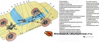
General structure of the working vehicle
The schematic diagram of the vehicle includes the following elements:
- brake mechanism;
- brake drive.
The brake mechanism implements the function of braking - achieving the torque that is necessary to reduce the speed of movement or stop.
The VAZ-2107 is equipped with a classic version of friction mechanisms based on friction force.
Their design can be represented by the following two options:
- disk (compression mechanism);
- drum (unclamping mechanism).
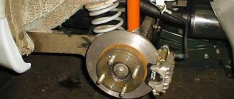
In the VAZ-2107, a disc mechanism is used on the front wheels, and a drum mechanism on the rear.
A brake actuator is needed to control the braking mechanisms. There are mechanical, pneumatic, hydraulic, electric and combined operating principles of drives. The VAZ-2107 uses the most common hydraulic principle, based on the action of brake fluid (a special oily substance).
The hydraulic drive circuit includes:
- brake pedal (to control the hydraulic drive);
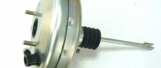
- vacuum booster (to create additional force when pressing the pedal);
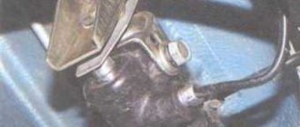
- master brake cylinder with an expansion tank (to ensure an increase or decrease in fluid pressure in the dual-circuit system, as well as to replenish fluid);
- wheel (or working) cylinders (to bring the control functions of the pedal to the brake mechanism);
- rear brake pressure regulator (to adjust the braking force as the vehicle weight increases);
- pipelines and hoses (for placing and moving brake fluid throughout the system).
The implementation of braking functions in the VAZ-2107 (as well as in related models - sedans 2101, 2103, 2105, 2106 and station wagons 2102, 2104) involves the use of two parallel independent hydraulic drive circuits. In the event of a malfunction of one circuit, the braking functions are redistributed to the second.
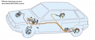
Operating principle of a hydraulic working vehicle
The functioning diagram of the VAZ-2107 brake system is typical. Pressing the brake pedal (through the vacuum booster) moves the piston in the master cylinder, which creates fluid pressure and forces it to move through the pipelines to the wheel brake mechanisms.
Under the influence of fluid pressure, the cylinder pistons help move the brake pads of the front wheels to the discs, and the rear wheels to the drums. The result of the movement of the pads is their contact with the discs and drums and the slowing down of the latter. The friction force of the braking wheels with the surface of the roadway leads to a general slowdown of the vehicle.
The braking stop circuit involves releasing pressure on the brake pedal and moving the fluid back to the master cylinder. This means a drop in fluid pressure in the system and loss of contact between the pads and drums and discs, that is, the cessation of braking.
The same principle underlies the braking process on “classic VAZ models (from 2002 to 2106). The only exception that the VAZ-2101 system circuit has is the absence of a vacuum booster.
Instructions for installing the HCD on VAZ 2101 – 2107
The package includes:
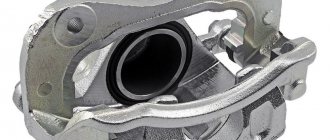
- Left caliper VAZ 2108 – 1 pc.
- Right caliper VAZ 2108 – 1 pc.
- Shoe guide VAZ 2108 – 2 pcs.
- Front brake flexible hose – 2 pcs.
- Faceplate – 2 pcs.
- Distance washer – 2 pcs.
- Brake disc boot – 2 pcs.
- Half ring – 2 pcs.
- Brake pads Ladasport VAZ 2108 – 1 set.
- Brake disc VAZ 2108 – 2 pcs.
VAZ 2101 axle shaft, modified – 2 pcs.
Work order.
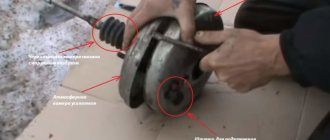
Place the car on a level surface. We install wheel chocks. Loosen the rear wheel mounting bolts. We jack up the car, completely unscrew the wheel mounting bolts and remove the wheel from the car. Remove the brake drum. We turn the axle shaft until the large holes coincide with the two nuts securing the brake shield. Using a 17 mm socket wrench with an extension, unscrew the nuts securing the brake shield. Turn the axle shaft and unscrew the remaining 2 nuts in the same way. We remove the semi-axle from the car. This can be done with a special puller or by securing the wheel with 2 bolts to the axle shaft.
With a sharp movement towards ourselves, we pull out the axle bearing from the flange of the rear axle beam. After unscrewing the bolts, remove the wheel. We take out the axle shaft. Remove the brake pads. Using a 10mm wrench, unscrew the brake pipe from the back of the brake shield. Remove the brake shield completely. We inspect the axle shaft seal and replace it if necessary. Take the modified axle shaft from the delivery kit. Install a half ring between the bearing and the oil reflective shield. Put the faceplate on and orient it so that the holes on the faceplate and the oil deflector plate line up. Place the brake disc boot on the rear axle beam. Install the axle shaft with the faceplate into the rear axle beam. Attention! The holes for attaching the brake mechanisms should be oriented so that the brake mechanism is located in front (in front of the bridge), the holes should be directed downward, as in the photo below. Tighten the 4 axle nuts. Attach the brake disc boot to the faceplate. Place the spacer on the axle shaft. Orient the washer so that the holes in the washer and the axle shaft line up. Install the brake disc and secure it to the axle flange. Install the caliper assembly onto the faceplate and tighten it with two M10 bolts. Attention. The fitting on the brake cylinder should point upward. Connect the brake hose to the brake pipe. Secure the brake hose with plastic ties
Secure in such a way that the hose does not have constant contact with other parts. Install the wheel. To secure the wheel, you must use extended bolts. Or replace the bolts with studs. Lower the car. Tighten the wheel bolts. Repeat steps 4-27 on the second side. Check the oil level in the rear axle gearbox. Add oil if necessary. Bleed the brake system.
Absolute vehicle malfunctions
During operation, the braking functions of the system deteriorate. This is due to wear and tear of components, assemblies and parts that require repair. Some vehicle malfunctions are included in a special “List...”, and driving with them is prohibited.
Inefficiency of the working vehicle
The most common malfunction of the brake system (including the VAZ-2107) is inefficiency, which is diagnosed by two main parameters (when carrying out a specialized instrumental study):
- increasing braking distance;
- increase in steady deceleration during braking.
Relative vehicle malfunctions
This list of faults does not apply to absolute (or categorical) faults. Their presence is associated with the convenience (or inconvenience) of driving.
Increased hydraulic pedal travel (as an option - a “soft” pedal)
The reasons for the “sinking” of the pedal are determined by the presence of air in the system; extreme wear of brake pads; failure of the main or wheel cylinders. The action plan for eliminating technical problems includes checking and repairing all components and assemblies of the system; and, if necessary, replacing failed ones and bleeding the system.
Shift towards the vehicle's trajectory when braking
The malfunction is due to either a failure of the working (wheel) cylinder or wear of the pads. Replacing them (or repairing them) will solve the problem.
Increased background noise, friction (grinding) in the brake mechanism
Deficiencies are localized mainly in the rear mechanisms and are determined by contamination of the mechanism, critical wear of the pads, breakage of spring elements, uneven wear of discs or drums. Fault repair involves washing and replacing mechanism parts.
Vibration when braking
This is a fairly common malfunction that is associated solely with critical or uneven wear of the discs or drums, and the repair will consist of replacing them. » alt=»»>
Replacing the parking brake cable:
In most cases, the tension of the handbrake cable is adjusted by its tension at the point of attachment to the equalizer. However, if adjustment cannot be made, replacement will be required:
- Remove the brake drum.
- Remove the muffler from the hanging clips and lower it to the ground.
- Dismantle the equalization device.
- Remove the cable end from the equalizer.
- Release the cable attachment to the body elements.
- Remove the opposite end of the cable from the brake mechanism by disconnecting it from the drive lever. Pull the cable out of the stationary shield.
- Carry out reverse laying, fixing and tensioning of the cable.
Summarize
The brake system of the VAZ-2107, like any other car, is an important component of an integral vehicle control system that ensures traffic safety.
Diagnostics and timely repair of vehicles is a vital necessity.
Let's first take a look at what brake systems are available in this car model. There are only two of them:
A working vehicle is used to allow the vehicle to reduce speed and stop. The parking lock fixes the vehicle in a stationary state when the driver needs it. They do not depend on each other, but setting off on a journey knowing that one of them is faulty is strictly prohibited. Naturally, the front and rear brakes should also always be replaced in a timely manner.
Brake system in Lada cars of the 2101-07 family
The braking system (TS) of any vehicle is designed to control the speed of movement, stop and hold it stationary for the required period of time.
It is one of the most important vehicle control systems, since road safety functionally depends on the degree of serviceability and efficiency of the braking system.
General structure of the braking system
The schematic diagram of the vehicle includes the following elements:
- brake mechanism;
- brake drive.
The brake mechanism implements the function of braking - achieving the torque that is necessary to reduce the speed of movement or stop.
The VAZ-2107 is equipped with a classic version of friction mechanisms based on friction force.
Their design can be represented by the following two options:
- disc (compression mechanism) front brakes;
- drum (unclosing mechanism) rear brakes.
A brake actuator is needed to control the braking mechanisms. There are mechanical, pneumatic, hydraulic, electric and combined operating principles of drives. The VAZ-2107 uses the most common hydraulic principle, based on the action of brake fluid (a special oily substance).
The hydraulic drive circuit includes:
- brake pedal (to control the hydraulic drive);
- vacuum booster (to create additional force when pressing the pedal);
- master brake cylinder with an expansion tank (to ensure an increase or decrease in fluid pressure in the dual-circuit system, as well as to replenish fluid);
- wheel (or working) cylinders (to bring the control functions of the pedal to the brake mechanism);
- rear brake pressure regulator (to adjust the braking force as the vehicle weight increases);
- pipelines and hoses (for placing and moving brake fluid throughout the system).
The implementation of braking functions in the VAZ-2107 (as well as in related models - sedans 2101, 2103, 2105, 2106 and station wagons 2102, 2104) involves the use of two parallel independent hydraulic drive circuits. In the event of a malfunction of one circuit, the braking functions are redistributed to the second.
How does it all work
The principle of operation of the VAZ 2107 brake system can be briefly described as follows:
- The driver, while driving along the highway, decides to slow down or stop.
- To do this, he presses the brake pedal with his foot.
- This force immediately falls on the valve mechanism of the amplifier.
- The valve slightly opens the supply of atmospheric pressure to the membrane.
- The membrane acts on the rod through vibration.
- Next, the rod itself exerts pressure on the piston element of the master cylinder.
- The brake fluid, in turn, begins to move the pistons of the working cylinders under pressure.
- Due to pressure, the cylinders are expanded or pressed (depending on whether disc or drum brakes are on a given vehicle axle). The mechanisms begin to rub the pads and discs (or drums), due to which the movement speed is reset.
Basic faults
The brake system itself is quite simple, but some of its elements require special attention. Main types of faults:
- The brake fluid leaks, resulting in a drop in pressure in the system. If a preliminary inspection does not find a leak, it is necessary to check the brake master cylinder. We bend the noise-insulating mat located under the brake pedal and inspect for streaks in the area of the rubber seal of the master cylinder. The presence of drips will indicate that the cause has been found and requires disassembling the cylinder and then replacing the cuff. If there is a vacuum booster, the brake master cylinder must be removed and inspected.
- When you release the brake pedal, the car drives sluggishly. Reason: the rear or front pads are jammed. Seized pads are identified by checking the heat of the corresponding wheel. We touch each disk - the hottest one will be jammed. In the case when these are the front wheels, you can, after removing the wheel, move the brake cylinder. If this fails, you will have to replace it with a new one. In the case of rear pads, the brake wheel cylinder will need to be replaced.
- When you press the pedal, braking does not occur, but it does when you press it several times in a row. This may indicate the presence of air in the system. The solution to the problem is to bleed the brakes to remove air.
- Problem with the handbrake. Most often this problem occurs in winter. It manifests itself in the fact that after a long period of parking, when the handbrake is released, the wheels remain locked. The reason is that the parking brake cable is frozen. During its operation, moisture gets there and freezes in winter. If the casing is severely damaged, it will have to be replaced.
Brake master cylinder diagram
Vibration when braking
This is a fairly common malfunction that is associated solely with critical or uneven wear of the discs or drums, and the repair will consist of replacing them.
Car shifts to the side when braking
The malfunction is due to either a failure of the working (wheel) cylinder or wear of the pads. Replacing them (or repairing them) will solve the problem.
The VAZ 2107 brake pedal fails: the main reasons
The brake system must be sealed and free of air. If the pedal begins to fail, then, with a greater degree of probability, we can say that depressurization has occurred, that is, air has entered the system.
- rust formation on the pedal linkage;
- failure of the vacuum booster;
- unadjusted distance between the cylinder piston and the pedal itself;
- lack of fuel fluid in the system.
It is also important to remember that brake fluid is an aggressive substance that can destroy thin pipes and even lines. That is why it is important to use only high-quality TZ. Low-quality liquid can form cracks through which it then flows out safely. But the flip side of the coin is that when you press the brake pedal, air leaks through these cracks.
↑ Checking wheel cylinder parts
↑ Wheel cylinders
Check the cleanliness of the working surfaces of the cylinder, pistons and thrust rings. The surfaces must be completely smooth, without roughness, to prevent fluid leakage and premature wear of seals and pistons. Eliminate defects on the cylinder surface by lapping or grinding. However, increasing the internal diameter of the cylinder is not allowed.
↑ Wheel cylinder parts
1 — piston assembly; 2 — cylinder body; 3 - thrust screw; 4 - thrust ring; 5 - crackers; 6 - spring; 7 — support cup; 8 - seal; 9 - piston; 10 - protective cap
Check the condition of the thrust screw 3, spring 6, support cup 7 and cotters 5. If necessary, replace damaged parts with new ones.
Replace the seals 8 with new ones. Check the condition of the protective caps 10 and replace them if necessary.
↑ Pads
Carefully check the pads for damage or deformation.
Check the elasticity of the tension springs, both upper and lower; if necessary, replace them with new ones.
The springs must not have residual deformations when stretched with a force of 343 N (35 kgf) for the lower springs and 411 N (42 kgf) for the upper ones.
Check the cleanliness of the linings, if dirt or traces of grease are found, thoroughly clean the linings with a wire brush and rinse with white spirit, in addition, check for any leakage of grease or oil inside the drum; eliminate the faults. Replace the pads with new ones if the thickness of the linings is less than 1.5–2 mm.
↑ Brake drums
Inspect the brake drums. If there are deep grooves or excessive ovality on the working surface, rebore the drums on the machine.
Then use a lathe to sand the drums with fine-grained abrasive stones. This increases the durability of the linings and improves uniformity and braking performance.
The largest permissible increase in the nominal diameter of the drum (250 mm) after boring and grinding is 1 mm. The limits of this tolerance must be strictly observed, otherwise the strength of the drum as well as the braking efficiency will be compromised.
Source