The vacuum booster of the VAZ 2107 brake system is considered a reliable unit, since it rarely fails. The first problems with the element occur after 150–200 thousand kilometers. If a malfunction is detected, the problem can be solved in two ways - complete replacement or repair of the unit. Having studied the design and principle of operation of the amplifier, the skilled owner of the “seven” can implement both options independently.
- Design and principle of operation of VUT
Video: how a vacuum brake booster works
- Video: how to check the vacuum brake booster on the “seven”
- Video: replacing the VAZ 2107 vacuum booster with your own hands
- Video: how to change the VUT diaphragm on a “classic”
Symptoms of a problem
- Stiff brake pedal when the engine is running.
- When you press the pedal, the engine starts to rev, and when you slow down sharply, it stalls completely. The described symptom of malfunction is typical for cars in which the vacuum for VUT operation is taken from the intake manifold. If the membrane or vacuum tubes are not sealed, when you press the brakes, unaccounted air will be sucked in, so the engine stalls and begins to stall. The described symptom of VUT malfunction does not apply to cars in which the vacuum is created by a vacuum pump.
How to check?
A torn diaphragm is the main cause of vacuum brake booster failure. The operating principle of the amplifier is based on the difference in pressure in the vacuum and atmospheric chambers, which provides additional retracting force on the pedals. If the vacuum chamber, for example, due to a rupture of the membrane, is connected to a medium with atmospheric pressure, the vacuum created will not be enough for the normal operation of the amplifier.
- Start the engine and press the brake pedal all the way. The appearance of hissing indicates that the VUT is not sealed, so air is leaking through it;
- Press the brake pedal vigorously 3-4 times. Keep it pressed and start the engine. If the vacuum seal is working properly, after starting the engine, the force on the pedal will change and it will go down a little.
Repair or replacement?
During production, parts of the amplifier housing are connected by rolling. At home, it is impossible to replicate the factory quality of rolling. Gaps in the contact areas of the housing parts will lead to leaks in the system. Therefore, in the event of a malfunction, a complete replacement is recommended.
System design
You can learn the operating principle and design of the VUT from the article “How a vacuum brake booster works.” But for proper replacement with your own hands, it is much more important to understand the general structure of the brake system with a vacuum booster. The VUT is attached to the engine shield and is connected only to the main brake cylinder and the pedal lever.
What does it consist of
- Frame
- Membrane (diaphragm)
- Fitting for air bleed from the chamber
- Bypass and atmospheric valve
- Air filter
- Pedal pusher and master cylinder piston rod
The body consists of two parts, separated by a rubber membrane or diaphragm. The first part is located closer to the main cylinder - the vacuum chamber. In it, from the intake manifold or carburetor through a hose and a fitting with a check valve, a vacuum (vacuum) is created.
The second is atmospheric, it has a connection with the outside air. This separation is necessary for it to perform its main task - to assist the driver when braking, to reduce the force on the pedal when pressed.
The diaphragm divides the body into two chambers. It is made of rubber to always remain elastic. It is not allowed to break it. In this case, the efficiency of the vacuum seal decreases and problems arise during engine operation; more on this below.
The fitting connects the housing cavity with vacuum to the engine intake manifold in the injection “sevens”, or the carburetor body under the throttle valves using a flexible hose. It is equipped with a check valve. This protects the vacuum booster from exhaust gases entering it. This can happen when the engine intake valves are not completely closed. Exhaust gases “break through” into the intake manifold through the hose and can damage the membrane.
The second function of the valve is to allow emergency braking in the event of an engine stop. It will close, maintaining a vacuum in the chamber. This will be enough for one or two clicks.
The air filter is located on the pedal assembly side. It prevents the penetration of dust and debris from the environment into the cavity of the amplifier.
There are two separate rods in the body. The first is connected to the brake pedal in the cabin, the second is connected to the pistons of the master brake cylinder. If the driver keeps his foot on the brake but does not apply pressure, there is no impact on the master cylinder. This is necessary so that the brakes do not activate and wear on the brake pads does not increase. We'll talk about how it works below.
Symptoms and diagnostics
If the VUT malfunctions, the force on the pedals during braking may increase many times over. Driving under these circumstances is unsafe. All symptoms must be immediately diagnosed and the broken unit repaired.
Typically, the vacuum booster is not checked during routine maintenance, so it is important to watch for the following symptoms:
- The pedal became hard. The main indicator that the VUT is worn out or is not working correctly. This may happen gradually or happen suddenly. In addition, the pedal may be positioned higher than usual.
- The braking distance has lengthened. This occurs because it is impossible to obtain the force on the master cylinder rod necessary for the design speed of stopping the vehicle.
- The engine stalls when the brakes are applied. This occurs when the amplifier diaphragm has lost its seal and allows air to leak past the seals. In addition to reduced braking ability, engine stalling can cause major problems on the road.
- The brake system stops working. The failure may be due to a malfunction of the VUT valves.
There is a simple test to evaluate the performance of a servo amplifier. To begin the test, you need to bleed the brakes with the engine off. Five or six clicks will be enough. This will release the vacuum from the tank. Then you should start the engine while lightly pressing the brake pedal. If the amplifier is working properly, the pedal will give a little and then harden. If the VUT is not working correctly, then either nothing will happen, or the pedal will push your foot immediately after starting the engine.
A defective amplifier must be immediately replaced or repaired. If you suspect a malfunction, you cannot continue operating the vehicle. The possibility of self-intervention depends on the specific type of device. Replacing most amplifiers is not difficult for a home mechanic, but it is better to do this procedure in a service station. Working with a repair kit (it may include a diaphragm, valves, rubber seals) clearly requires knowledge and qualifications.
Possible mechanism malfunctions
The first sign of a breakdown of the brake system vacuum booster is an increase in effort when pressing the pedal (if the device is in working order, pressing the brake pedal is soft and smooth). In this case, the brake mechanism continues to work, but causes inconvenience in driving. The driver needs to make more and more efforts to reduce speed in a timely manner. The part in question cannot be repaired, so if it malfunctions, it will need to be replaced. If you do not replace the vacuum booster on the VAZ 2107, then such operation of the car may result in an accident.
The design of the device in question includes the following parts:
- steel body or base;
- valve;
- polymer membrane;
- rubber membrane.
The following types of malfunctions of the mechanism in question are distinguished:
Brake force animation
A modern car is in most cases equipped with two intermediate systems that work as converters of pressure on the brake pedal into the force of pressing the pads against the discs: hydraulic and vacuum. The fluid circuit performs several functions simultaneously.
Its heart is the brake master cylinder (MBC), whose tasks include:
- Creating high braking force on the calipers by multiplying the pressure on the pedals and transferring it to the place of application.
- Reducing frictional wear of moving parts by replacing mechanical components with hydraulic ones.
- Distribution of braking force between the front and rear wheels.
- Providing design flexibility by creating work circuits that are independent from each other. This reduces the likelihood of brake failure.
- Providing technical simplicity compared to mechanical solutions.
- Simplify maintenance.
However, the speeds and masses of vehicles are so high that the hydraulic system's capabilities are insufficient for the force on the cylinder rod to be considered negligible.
avtoexperts.ru
A vacuum brake booster, like any other mechanism, has its own service life. In order to identify a breakdown in time and find its cause, you need to understand how this mechanism works. Therefore, we suggest further understanding the scheme of its operation, the most common causes of malfunctions and methods for independently diagnosing this unit.
Purpose
The vacuum brake booster, as you might guess, increases the pressure that the driver puts on the brake pedal. As a result, braking is much easier. Without it, the driver would have to press hard on the brake pedal, and still, braking would not be as effective.
Thus, the vacuum cleaner is an important driver’s assistant, which makes driving safer.
The device of the “vacuum generator” and the principle of operation
The vacuum amplifier is a sealed container separated by a rubber membrane with a rod into two chambers. One chamber is atmospheric, that is. the pressure in it is equal to the atmospheric pressure, and the second is vacuum. In reality, there is no complete vacuum in it, but only a greatly reduced pressure, but it is customary to call it vacuum. Hence the name of the amplifier.
True, in some cases, for stable operation of the system, a vacuum pump is responsible for providing vacuum. For example, in diesel engines, the pressure in the manifold decreases to a lesser extent than in gasoline engines, so the use of a vacuum pump is simply necessary. The latter can be either electrical or mechanical, powered by a camshaft. But in any case, the pump performs only an auxiliary function.
At rest, i.e. when the brake pedal is not operated by a person, both chambers communicate with each other through a vacuum valve, while the atmospheric valve located in the atmospheric chamber is closed. Since the pressure in both chambers is the same, the membrane is also at its original point, that is, in the center of the pump.
When the brake pedal is depressed, the vacuum valve closes and the atmospheric valve opens. As a result, different pressures arise in the chambers; accordingly, the membrane bends towards the vacuum chamber, since atmospheric pressure presses on it with enormous force. In this case, the rod, which is connected to the brake pedal and the hydraulic cylinder piston, is deflected to the side along with the membrane and actuates the piston of the master cylinder, which in turn increases the pressure of the brake fluid. As a result, it is transmitted to the pistons of the wheel brake cylinders connected to the pads. As a result, the braking process occurs.
It must be said that the brake pedal is necessarily connected not only to the vacuum membrane rod, but also to the hydraulic cylinder piston. This is necessary so that the brake system can operate even if the vacuum booster fails. For example, if the engine stalls, you can still apply the brakes. When the pedal returns to its original position, the atmospheric valve is blocked and at the same time the vacuum valve opens. Accordingly, a discharged pressure arises in both chambers, as a result of which the membrane with the rod also returns to its original position.
The most common faults
Most often, motorists have to deal with the following problems associated with the operation of the vacuum cleaner:
• Depressurization of the hose connecting the amplifier to the intake manifold;
• Wear of the vacuum valve;
• Depressurization of working chambers.
Typically, car enthusiasts have to deal with the first two breakdowns. As a rule, you can determine the depressurization of the system even by the sound of the engine. When you press the brake, the engine speed increases or, on the contrary, drops significantly until the engine stalls. This is due to the fact that air leaks affect the quality of the fuel mixture entering the cylinders, and accordingly, changes occur in the operation of the engine.
Note! If you hear a hissing sound when you press the brake pedal, this is a clear sign of depressurization of the system, resulting in air leaks. He is the source of this sound.
It is even easier to determine the complete failure of the vacuum seal, since pressing the brake becomes very difficult, much the same as when the engine is turned off. But there are situations when a given unit does not completely fail, so it is more difficult to determine the malfunction. But for an experienced motorist nothing is impossible.
Diagnosing the malfunction
First of all, we note that a vacuum booster is not a hydraulic booster, with which motorists often confuse it. If when the latter fails, a leak appears and the brake pedal may fail, then, as mentioned above, the failure of the vacuum seal only makes the brake pedal harder.
However, if the main brake cylinder comes out, brake fluid can be thrown into the booster, and the pedal may fail. But this is a separate part of the brake system, so we will discuss it in another topic.
How to change it yourself
Let's look at how to change the VUT using the example of the VAZ 2110, 2111, 2112. The design of the system is quite monotonous, therefore, after watching the video, you can replace the vacuum brake booster of the VAZ 2114 and many other cars.
- Remove the low brake fluid level sensor connector.
- Unscrew the 2 bolts 17 securing the brake cylinder to the VUT body. There is no need to unscrew the lines, just move the cylinder with the tank a little to the side.
- Disconnect the vacuum hose from the check valve. Check the condition of the valve and install it on the new brake booster.
- Unscrew the 4 bolts securing the VUT to the engine shield. The working space in the area of the pedal assembly on the interior side is limited, so an extended socket, extension and ratchet are best suited for unscrewing.
- Disconnect the brake sensor connector.
- Pull out the VUT along with the mounting bracket and the brake pedal.
- Using pliers, remove the locking plate of the brake pedal lever rotation axis.
- Pull out the “finger” that secures the VUT pusher in the lever.
- Unscrew the 2 nuts securing the vacuum body to the bracket.
The brakes stopped working
In the worst case scenario, the brake booster control valve fails completely, resulting in complete inoperability of the brake system. Fortunately, such an outcome is unlikely. But if suddenly it does occur, carefully stop the car, tow it home and contact a qualified specialist in the diagnosis and repair of brake systems. Depending on the severity of the case, the matter may be limited to only replacing the valve, but serious repairs of the entire brake system may be required.
The brake booster control valve is an important element of the braking system, ensuring driving safety. That is why the presence of the described symptoms should not be ignored or postponed “for later”. Contact a qualified mechanic who can professionally diagnose and repair your vehicle's brake system.
How to check the vacuum brake booster
Checking the vacuum brake booster is a simple procedure that even a novice car enthusiast can handle. To determine if a part is malfunctioning, it does not need to be removed from the machine; all you need to do is perform 3 simple tests that indicate the problem.
Test 1
The car must be started and allowed to idle for about 5-7 minutes. Next, the engine is turned off, and the driver needs to fully depress the brake pedal to create a vacuum in the brake booster. The pedal is then released and pressed down again.
If there is a problem with the vacuum brake booster, the second time you press the brake pedal, the pedal travel will be significantly less than the first time because vacuum can no longer be created. In a situation where the second press does not differ from the first along the pedal stroke, we can conclude that the system is working properly or, if there is no certainty, move on to the next test.
Test 2
When the car engine is turned off, you need to press the brake pedal several times (6-8). Next, the pedal is depressed as much as possible and the engine starts. If there are no problems with the operation of the vacuum brake booster, a vacuum will begin to create in the system. As a result, the membrane presses on the rod, it pulls the pusher, which is connected by a mechanism to the pedal. Accordingly, at this moment the pedal, even if it is pressed all the way, will begin to drop slightly even lower.
If the fully depressed pedal does not budge after starting the engine, we can conclude that no vacuum has been created in the system. Accordingly, there are malfunctions that interfere with this process.
Test 3
The third way to check the vacuum brake booster allows you to determine whether there are air leaks.
To carry out diagnostics, you need to start the car engine. Next, the pedal is pressed all the way and the engine is turned off. If within 30 seconds the pedal does not deviate from the maximum depressed state, there are no problems with the vacuum brake booster. When, after releasing the pedal, it begins to return to its reverse position under the action of the return spring, this indicates that the pressure inside the working chamber increases, which indicates a malfunction of the mechanism.
Checking the operation and replacing the vacuum booster check valve
Step-by-step instructions with photo accompaniment on how to check the operation of the check valve of the vacuum booster and replace it.
Step-by-step instructions with photo accompaniment on how to check the operation of the check valve of the vacuum booster and replace it.
If the first symptoms of poor performance appear with the brake system, then an inspection should be performed to find faults. Usually the first symptoms appear when you press the brake pedal. And this, in turn, is a malfunction of the vacuum brake booster - the main “assistant” of the entire braking system.
To check the functionality of the vacuum booster, with the car engine turned off, you need to make 5-6 consecutive presses of the brake pedal with an interval of 1-2 seconds and do not release the pedal for the sixth time - hold it pressed. Now, in this position, start the engine, the pedal should move forward. If nothing happens, then you need to check the vacuum hose and the operation of the check valve for leaks, which is what we will now do in this article.
The whole procedure is very simple and does not require additional outside help; everything can be done in the garage with your own hands. The most inconvenient and tedious thing is dismantling the trim under the hood, otherwise you won’t be able to get to the vacuum brake booster.
History of appearance
The automobile industry began to gain momentum at the end of the 19th century. At the dawn of the evolution of self-running crews, little attention was paid to brakes - they were simply not needed. The friction in the transmissions was so great that the vehicles slowed down sufficiently in the absence of traction. However, the power and weight of engines grew, and already at the beginning of the 20th century, many devices designed to stop vehicles were patented.
Some innovations of that period were ahead of their time. For example, four years after the appearance of Karl Benz's car, British engineer Frederick Lanchester patented a disc brake. It took several decades for this invention to become widely accepted.
The first use of air for braking was demonstrated on its model by the Chicago manufacturer Tincher. Pressure was generated by a small pump and could be used for braking, inflating tires, or sounding a horn. The 1928 Pierce-Arrow was the pioneer of vehicles equipped with a modern vacuum brake booster.
However, despite their effectiveness, until the mid-20th century, such systems were offered by automakers only as an option. The fact is that to operate the drum brakes, the force of the foot on the pedal was sufficient. It was only with the spread of a more efficient method of braking using a disc-pad pair that servos became standard equipment. The main dates in the history of the modern vacuum pump can be considered:
- 1920s - Several inventors work on actuators for aviation using vacuum in the intake manifold.
- 1927 - Belgian engineer Albert Devandre invented a vacuum brake servo.
- 1928 - the first production car with VUT.
- Second half of the 20th century - the system becomes commonplace for production models.
How does the braking system work?
To understand why the brake pedal sometimes fails, you need to understand the general principle of operation, as well as the design of the braking system. It is usually hydraulic, and the problems are common for different car models. The operating principle of the system is based on the fact that a special incompressible liquid is placed in a closed volume.
Hydraulic brakes include the following elements :
GTZ (brake master cylinder);
RTC (brake wheel cylinders);
brake discs, pads.
The working fluid here, in accordance with the name, is brake fluid, which has certain properties. The driver presses the brake, his force is transmitted to the GTZ filled with working fluid. The fact is that the device of this element contains a piston - it presses on the liquid, and through it the force is transmitted to the RTC. The latter are installed in the area where the wheels are located. Thus, the pads are pressed against the brake discs/drums. Sudden pressure on the pedal causes the pads to rigidly block the wheels.
Next, the driver releases his foot, and the return springs move the pads back. At the same time, the liquid is displaced into the GTZ. This short list represents the entire operation scheme of this system.
Recommended articles to read:
Purpose and location of the unit
The first classic Zhiguli models (VAZ 2101–2102), produced without amplifiers, were distinguished by a “tight” brake pedal. To stop the car suddenly, the driver had to exert considerable effort. In the 70s of the last century, the manufacturer began equipping cars with vacuum boosters (abbreviated as VUT), which significantly increased braking efficiency and made the driver’s work easier.
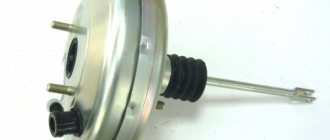
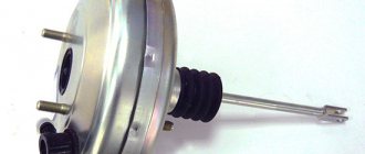
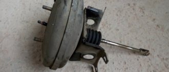
The unit in the form of a metal “barrel” is installed on the bulkhead between the engine compartment and the interior of the VAZ 2107, on the driver’s side. VUT attachment points:
- the body is screwed to the partition with 4 M8 nuts;
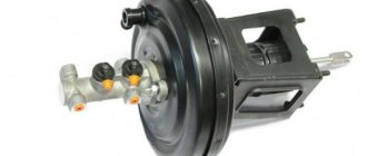
- the master brake cylinder is attached to the booster in front on 2 M8 studs;
- the push rod of the element goes inside the passenger compartment and is connected to the brake pedal lever.
The booster's job is to help the driver apply pressure to the master cylinder rod using vacuum force. The latter is created using vacuum taken from the engine through a special pipe.
The vacuum selection hose is connected to the intake manifold from the side of the channel leading to cylinder III. The second end of the pipe is connected to the fitting of the check valve installed outside the VUT housing.
Essentially, the vacuum booster does the physical work for the driver. The latter only needs to lightly press the pedal for the car to begin to slow down.
Design and principle of operation of VUT
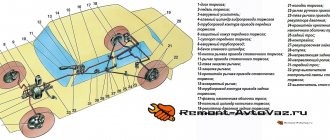
The vacuum amplifier is a metal “barrel” consisting of the following parts (the numbering in the list coincides with the positions in the diagram):
- The body is cylindrical in shape.
- Pressure rod of the main brake cylinder.
- A cover connected to the body by point rolling.
- Piston.
- Bypass valve.
- Brake pedal pusher.
- Air filter.
- Buffer insert.
- Internal plastic housing.
- Rubber membrane.
- Spring for return of the inner housing with membrane.
- Connection fitting.
- Check valve.
- Vacuum pipe.
The letter “A” in the diagram indicates the chamber for supplying vacuum, the letters “B” and “C” are the internal channels, and “D” is the cavity communicating with the atmosphere. Rod pos. 2 rests against the mating part of the main brake cylinder (abbreviated as GTZ), the pusher pos. 6 is attached to the pedal.
The unit is capable of operating in 3 modes:
- The engine is running, but the driver does not press the brake. Vacuum from the manifold is supplied through channels “B” and “C” into both chambers; the valve is closed and does not allow atmospheric air inside. The spring holds the diaphragm in its original position.
- Standard braking. The pedal is partially pressed, the valve releases air (through the filter) into chamber “G”, which is why the vacuum force in cavity “A” helps to press on the GTZ rod. The plastic body will move forward and rest against the piston, and the movement of the rod will stop.
- Emergency braking. In this case, the effect of vacuum on the membrane and housing is not limited; the master cylinder rod is squeezed all the way.
After releasing the pedal, the spring throws the body and membrane back to their original position, and the atmospheric valve closes. The check valve at the inlet of the pipe serves as protection against sudden air injection from the manifold.
Gas breakthrough into the intake manifold and further into the brake booster occurs on extremely worn engines. The reason is a loose fit of the intake valve to the cylinder head seat. During the compression stroke, the piston creates a pressure of about 7-8 atm and pushes some of the gases back into the manifold. If the check valve does not work, they will begin to penetrate into the vacuum chamber, reducing the efficiency of the VUT.
Video: how a vacuum brake booster works
↑ Brake light adjustment
If the brake light switch is too close to the pedal, then it does not return to its original position, valve 9 (see Fig. 7–2), pressing against body 22, separates cavities A and E, and the wheels are incompletely released when the pedal is released.
The position of the brake light switch is adjusted by moving it when nut 5 is released (see figure). Install it so that the brake light buffer lightly touches the pedal stop, while the pedal free play should be 3–5 mm. After completing the adjustment, tighten nut 5.
WARNING! Adjust the free play of the brake pedal with the engine not running.
Brake booster malfunctions
Since the braking force is replaced using vacuum, most VUT malfunctions are associated with loss of tightness:
- breakdown of the rubber diaphragm due to critical wear;
- air suction along the edge of the body - at the junction between the two covers;
- the same, through the seal on the GTZ rod;
- problems with the vacuum selection hose - cracks or suction at the joints.
Much less common is failure of the internal bypass valve, clogging of the air filter, and shrinkage of the spring due to natural wear. In very rare cases, the spring breaks into 2 parts.
One day, an acquaintance of mine encountered an interesting effect - the “seven” slowed down tightly after starting the engine. The malfunction was preceded by constant overheating of the brake discs and drums on all wheels. It turned out that two breakdowns occurred inside the vacuum booster at once - the valve failed and the return spring broke. When trying to start the engine, the VUT was automatically triggered by the vacuum, spontaneously squeezing the main cylinder rod. Naturally, all the brake pads were seized - it was impossible to move the car.
Sometimes there is a brake fluid leak between the GTZ flange and the vacuum booster. But this problem does not apply to VUT failures, because fluid is leaking from the main cylinder. The reason is wear and loss of tightness of the sealing rings (cuffs) inside the GTZ.
Troubleshooting
The first sign of loss of vacuum booster seal is not deterioration of the brakes, as many sources on the Internet describe the malfunction. When air just begins to leak through the leaky membrane, the VUT continues to function properly, since the motor manages to maintain a vacuum in the front chamber. The first symptom is changes in the operation of the engine itself:
- due to air leaks into the third cylinder, the engine begins to “trouble” at idle;
- crankshaft revolutions “float”, the stronger the suction, the greater the amplitude of oscillations;
- a running engine reacts to the brake pedal and stalls when pressed sharply;
- Gasoline consumption increases.
If a car owner ignores the primary symptoms, the situation gets worse - the pedal becomes harder and requires more physical effort to slow down and stop the car. The car can be used further; a breakdown of the VUT does not lead to a complete failure of the brakes, but it significantly complicates driving, especially if you are not used to it. Emergency braking will become a problem.
How to make sure that the vacuum booster is leaking:
- Loosen the clamp and remove the vacuum pipe from the fitting on the manifold.
- Plug the fitting with a tight homemade plug.
- Start the engine. If the revs level out, the problem clearly lies in the amplifier.
- Remove the high voltage wire and remove the spark plug for cylinder III. If the VUT fails, the electrodes will be smoked with black soot.
Whenever possible, I use the old “old-fashioned” method - I simply pinch the vacuum hose with pliers while the engine is running. If the third cylinder starts working and idle speed is restored, I proceed to checking the brake booster.
Similarly, the problem can be temporarily fixed while on the road. Disconnect the pipe, plug the fitting and calmly go to the garage or service station - the power unit will operate smoothly, without excessive fuel consumption. But remember, the brake pedal will become hard and stop responding instantly to light pressure.
Additional diagnostic methods:
- Press the brake 3-4 times and start the engine while holding the pedal. If it does not fail, the valve has probably failed.
- With the engine not running, disconnect the hose from the fitting, remove the check valve and firmly insert a pre-compressed rubber bulb into the hole. On a sealed amplifier it will retain its shape, on a faulty amplifier it will fill with air.
Using a bulb, you can accurately determine the location of the defect, but the vacuum booster will have to be removed. While pumping air into the chamber, wash the edges of the joints and the stem seal - bubbles will indicate the location of damage.
Video: how to check the vacuum brake booster on the “seven”
↑ Brake pedal design
1 - vacuum booster; 2 - pusher; 3 — brake pedal; 4 — brake light switch buffer; 5 — switch nut; 6 — brake light switch; 7 — pedal release spring; 8 – main cylinder.
The free play of the brake pedal when the engine is not running should be 3–5 mm. This value is obtained by adjusting the position of the brake light switch 6.
Replacement instructions
In the vast majority of cases, owners of "sevens" change the vacuum booster assembly, since repairing the unit does not always give a positive result. The main reason is difficulties in assembling, or more precisely, restoring the sealed factory rolling of the housing.
Replacement does not require special conditions or special devices; work is carried out in a garage or in an open area. Tools used:
- a set of sockets with an extension and a ratchet handle;
- socket wrench size 13 mm;
- 7 mm open-end wrench and caliper with depth gauge for adjustment;
- flat and Phillips screwdriver;
- pliers.
Along with the brake booster, it is worth changing the vacuum hose and clamps - old parts can cause air leaks.
Replacement of VUT is carried out in the following order:
- Loosen the clamp and disconnect the vacuum hose from the check valve fitting.
Assembly is performed in the same way, only in reverse order. Before installing a new VUT, be sure to adjust the length of the protruding part of the rod in order to provide the brake pedals with a slight free play. How to make the adjustment:
- Pull out the plastic buffer liner from the side of the GTZ flange, push the rod in until it stops.
- Using a depth gauge (or other measuring device), measure the length of the rod head protruding above the plane of the body. The permissible range is 1…1.5 mm.
It is also recommended to treat the rubber elements with a thick neutral lubricant before installation - this will extend the life of the unit.
Video: replacing the VAZ 2107 vacuum booster with your own hands
Unit repair - diaphragm replacement
This operation is unpopular among Zhiguli owners; usually car enthusiasts prefer to change the entire amplifier. The reason is that the result does not correspond to the effort expended; it is easier to buy and install the VUT assembled. If you definitely decide to disassemble and repair the vacuum amplifier, prepare the following tools and consumables:
- assembly spatula, powerful flat screwdriver;
- pliers;
- hammer;
- brush with metal bristles;
- large bench vice;
- repair kit for vacuum amplifiers VAZ 2103—2107;
- silicone sealant.
It is best to buy a repair kit from the Balakovo Rubber Products Plant. This company is a direct supplier of parts for AvtoVAZ and produces high-quality original spare parts.
To carry out repair work, the VUT must be removed from the vehicle, as described in the instructions above. Disassembly and replacement of parts is carried out in the following order:
- Place a mark on the body with a marker, flare the connections with the cover, bending the edges of the shell with a mounting blade.
After assembly, install the unit on the car, having adjusted the rod extension in advance (the procedure is described in the previous section). When finished, check the operation of the amplifier while running.