Thank you all for your response!
yaris
I have self-feeding cylinders.
It's all about the gap between the GTZ and the VUT rod! I have not seen anyone write about adjusting it in any article!
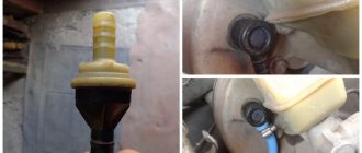
I quote: Before installing the master brake cylinder, we control the protrusion of the head of its adjusting bolt relative to the mounting plane of the master brake cylinder flange, which should be 1.25-0.2 mm
. To adjust the protrusion of the bolt head, turn it with an 8-point wrench.
This was the reason for the brakes being applied almost to the floor! But the “instructions” don’t say a word that the rod itself needs to be held with pliers and the “head” itself must be turned. And the key is not "on" 8
"But still "at
7
". I removed the GTZ three times to adjust the rod. And then this rod needs to be “inserted” back! I will say this is not very easy, since the pipeline is already connected and laid! It’s good that I didn’t leave the original brake fluid reservoir with its rubber hoses. I feel like I suffered even more then! The pedal began to take where it should be - in the middle! But “the music didn’t play for long!” Still, I guessed wrong.
Thanks again to Deeptown
for the hint where to dig, for the consultation at the moment when I stopped near the Dorogozhychi metro station with an oak pedal and almost blocked brakes. I had one adjustable wrench with me, thanks to it I unscrewed the GTZ and relieved the pressure. Then, on the floor with live brakes, I drove to the garage. There, within 5 minutes I removed everything, tightened the rod 5 turns and calmly drove home. But I see that I can add a couple more turns.
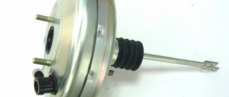
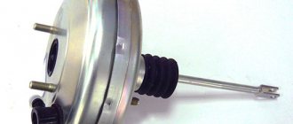
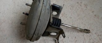
The vacuum brake booster (VBR) is one of the main components of the vehicle braking system. Even the slightest breakdown can trigger a failure of the entire system and lead to serious consequences.
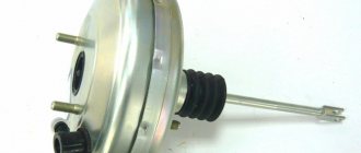
Brake booster
Almost all modern cars are equipped with vacuum brake boosters. They have a fairly simple design, but are very effective and quite reliable.
Purpose
The VUT serves to transmit and increase force from the pedal to the brake master cylinder (MBC). In other words, it simplifies the driver’s actions when braking. Without it, the driver would have to press the pedal with incredible force to force all the working cylinders of the system to function simultaneously.
Device
The VUT design consists of:
- housing, which is a sealed metal container;
- check valve;
- plastic diaphragm with rubber cuff and return spring;
- pusher;
- follower valve with rod and piston.
A diaphragm with a cuff is placed in the device body and divides it into two compartments: atmospheric and vacuum. The latter is connected through a one-way (non-return) valve to a source of air vacuum using a rubber hose. In the VAZ 2106, such a source is the intake manifold pipe. It is there that, during operation of the power plant, a vacuum is created, which is transmitted through a hose to the VUT.
The atmospheric compartment, depending on the position of the follow-up valve, can be connected both to the vacuum compartment and to the environment. The valve is moved by a pusher, which is connected to the brake pedal.
The diaphragm is connected to a rod, which is provided to push the master cylinder piston. When it moves forward, the rod presses on the GTZ piston, causing the fluid to be compressed and pumped to the working brake cylinders.
The spring is designed to return the diaphragm to its initial position upon completion of braking.
How it works
The functioning of the “vacuum tank” is ensured by the pressure difference in its chambers. When the car engine is turned off, it is equal to atmospheric pressure. When the power plant is running, the pressure in the chambers is also the same, but there is already a vacuum created there by the movement of the engine pistons.
When the driver presses the pedal, his force is transmitted to the follower valve through the pusher. Having shifted, it closes the channel that connects the compartments of the device. The subsequent stroke of the valve equalizes the pressure in the atmospheric compartment, due to the fact that the atmospheric channel opens. The pressure difference between the compartments causes the diaphragm to bend, compressing the return spring. In this case, the rod of the device presses on the GTZ piston.
The force created by the “vacuum driver” can exceed the driver’s force by 3–5 times. Moreover, it is always directly proportional to the applied.
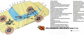
Location
VUT VAZ 2106 is installed in the engine compartment of the car on the left side of the engine shield. It is secured with four studs on the plate of the brake and clutch pedal bracket. The GTZ is fixed on the body of the “vacuum generator”.
Common breakdowns of VUT VAZ 2106 and their symptoms
Since the vacuum brake booster has a simple mechanical design, it rarely breaks down. But when this happens, it is better not to delay repairs, since driving with a faulty braking system is unsafe.
Breakdowns
Most often, the “vacuum tank” becomes unusable due to:
- violation of the tightness of the hose connecting the inlet pipe of the manifold and the VUT;
- check valve passage;
- rupture of the diaphragm cuff;
- incorrect adjustment of the rod protrusion.
Signs of a faulty VUT
Symptoms that the amplifier is broken may include:
- dips or too tight brake pedal travel;
- self-braking of the car;
- hissing from the amplifier housing;
- reduction in engine speed when braking.
Dips or difficulty moving the brake pedal
With the engine off and the power steering off, the brake pedal should be pressed with great force, and after 5–7 presses it should stop in the upper position. This indicates that the VUT is completely sealed and all valves, as well as the diaphragm, are in working condition. When you start the engine and press the pedal, it should move down with little force. If, when the power unit is not working, it fails, but does not squeeze out when the power unit is running, the amplifier is leaky and, therefore, faulty.
Spontaneous braking of the car
When the VUT depressurizes, arbitrary braking of the machine may occur. The brake pedal is in the upper position and is pressed with great force. Similar symptoms also occur when the protrusion of the rod is incorrectly adjusted. It turns out that due to its greater length, it constantly puts pressure on the piston of the main brake cylinder, causing arbitrary braking.
Hiss
A hissing “vacuum seal” is evidence of a rupture of the diaphragm cuff or a malfunction of the check valve. If a crack forms in the rubber cuff or detaches from the plastic base, air from the atmospheric chamber leaks into the vacuum chamber. This causes the characteristic hissing sound. In this case, braking efficiency decreases sharply, and the pedal falls down.
If the cuff is damaged, the seal of the chambers is compromised
Hissing also occurs when cracks form in the hose connecting the amplifier to the intake pipe of the manifold, as well as when the check valve, which is functionally designed to maintain a vacuum in the vacuum chamber, fails.
Video: VUT hissing
Reducing engine speed
A malfunction of the vacuum booster, namely its depressurization, affects not only the efficiency of the brake system, but also the operation of the power plant. If there is air leakage in the system (through a hose, check valve or diaphragm), it will enter the intake manifold, leaning the fuel-air mixture. As a result, when you press the brake pedal, the engine may suddenly lose speed and even stall.
Video: why the engine stalls when braking
How to check the vacuum booster
If the symptoms listed above occur, the vacuum unit must be checked. You can determine the functionality of the device without removing it from the car. For diagnostics, we need a rubber bulb from a hydrometer and a screwdriver (slotted or Phillips, depending on the type of clamps).
We carry out verification work in the following order:
- Turn on the parking brake.
- We sit in the cabin and press the brake pedal 5-6 times without starting the engine. On the last press, leave the pedal in the middle of its travel.
- We take our foot off the pedal and start the power plant. When the “vacuum” is working, the pedal will move down a short distance.
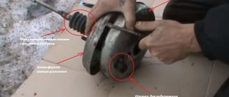
- If this does not happen, turn off the engine and move on to the engine compartment. We find the amplifier housing there, inspect the check valve flange and the end of the connecting hose. If they have visible breaks or cracks, we prepare to replace the damaged parts.
Video: checking VUT
Troubleshooting
The first sign of loss of vacuum booster seal is not deterioration of the brakes, as many sources on the Internet describe the malfunction. When air just begins to leak through the leaky membrane, the VUT continues to function properly, since the motor manages to maintain a vacuum in the front chamber. The first symptom is changes in the operation of the engine itself:
- due to air leaks into the third cylinder, the engine begins to “trouble” at idle;
- crankshaft revolutions “float”, the stronger the suction, the greater the amplitude of oscillations;
- a running engine reacts to the brake pedal and stalls when pressed sharply;
- Gasoline consumption increases.
Air leaking into the engine through the VUT causes the third cylinder to turn off - the engine begins to “trouble.”
If the car owner ignores the primary symptoms, the situation gets worse - the pedal becomes harder and requires more physical effort to slow down and stop the car. The car can be used further; a breakdown of the VUT does not lead to a complete failure of the brakes, but it significantly complicates driving, especially if you are not used to it. Emergency braking will become a problem.
How to make sure that the vacuum booster is leaking:
- Loosen the clamp and remove the vacuum pipe from the fitting on the manifold.
- Plug the fitting with a tight homemade plug.
- Start the engine. If the revs level out, the problem clearly lies in the amplifier.
- Remove the high voltage wire and remove the spark plug for cylinder III. If the VUT fails, the electrodes will be smoked with black soot.
Whenever possible, I use the old “old-fashioned” method - I simply pinch the vacuum hose with pliers while the engine is running. If the third cylinder starts working and idle speed is restored, I proceed to checking the brake booster.
Similarly, the problem can be temporarily fixed while on the road. Disconnect the pipe, plug the fitting and calmly go to the garage or service station - the power unit will operate smoothly, without excessive fuel consumption. But remember, the brake pedal will become hard and stop responding instantly to light pressure.
Additional diagnostic methods:
- Press the brake 3-4 times and start the engine while holding the pedal. If it does not fail, the valve has probably failed.
- With the engine not running, disconnect the hose from the fitting, remove the check valve and firmly insert a pre-compressed rubber bulb into the hole. On a sealed amplifier it will retain its shape, on a faulty amplifier it will fill with air.
Using a bulb, you can accurately determine the location of the defect, but the vacuum booster will have to be removed. While pumping air into the chamber, wash the edges of the joints and the stem seal - bubbles will indicate the location of damage.
Repair or replacement
Having discovered a faulty vacuum brake booster, you can go in two ways: replace it with a new one or try to repair it. It should be noted here that a new VUT without a master brake cylinder will cost approximately 2000–2500 rubles. If you don’t want to spend that much money and are determined to repair the unit yourself, purchase a repair kit for the old “vacuum unit.” It costs no more than 500 rubles and includes those parts that most often fail: cuff, shank cap, rubber gaskets, valve flanges, etc. Repairing an amplifier itself is not a very complicated process, but it is time-consuming. It involves removing the device from the car, disassembling, troubleshooting, replacing faulty elements, as well as adjustment.
Change the vacuum booster or repair it, the choice is yours. We will consider both processes, and start with replacement.
Replacing VUT with VAZ 2106
- thin slotted screwdriver;
- spanner set to “13”;
- socket wrench set to "13".
- Place the car on a flat surface and put it in gear.
- In the interior, we bend the carpet under the pedal bracket. We find there the junction of the brake pedal and the booster pusher.
- Using a slotted screwdriver, remove the spring retainer from the pedal mounting pin and the pusher shank.
After replacing the device, do not rush to install the master brake cylinder, since before this it is necessary to check and, if necessary, adjust the protrusion of the rod, which we will talk about after considering the VUT repair process.
Video: replacing VUT
Repair of the VAZ 2106 vacuum cleaner
- vice;
- slotted screwdriver;
- small hammer;
- pliers.
- We fix the vacuum booster in a vice in any convenient way, but only so as not to damage it.
- Using a slotted screwdriver and pliers, we flare the halves of the device body.
Adjusting the rod of the main brake cylinder VAZ 2106
If, when braking a car, you notice that the pressure on the brake pedal has noticeably increased, then you need to check the brake booster with the car stationary.
Repair
To get started, below is a complete list of tools that will be needed to replace it.
Flat screwdriver 13mm head Ratchet handle Extension
But before you begin this repair, you must first remove the brake master cylinder. After this, you need to fold back the carpet and pile inside the car, on the driver’s side, to gain access to the nuts for its fastening:
In the photo above you can see two side nuts on the right, and two more are on the left side, located in a similar place. Now we take a flat screwdriver and use it to pry off the lock washer of the rod that connects the vacuum booster rod to the brake pedal on the VAZ 2106.
Now we take it out when the top part is free.
Next, again, use a screwdriver to press on the rod so that it pops out from the back side:
With this all done, now you can move on. We unscrew all four nuts securing the amplifier, as is clearly shown in the picture below:
When all the nuts are unscrewed, from the reverse side, that is, from under the hood, you can remove the vacuum, since there are no more fasteners holding it:
Buying a new amplifier for a VAZ 2106 will cost 900 rubles. The price is certainly not low, although you can look for used ones in quite good condition. They will ask for no more than 300 rubles.
How to change brake pads follow the link.
Malfunctions
How should you check the VUT for serviceability without resorting to an inspection hole? This is done like this: when the engine is not running, you need to press the brake about 6 times. Then, holding this pedal, start the engine. The pedal should move forward a little, and if this does not happen, first of all you need to check the tightness of the hose connections and the operation of the check valve.
If your vacuum brake booster hisses, then you definitely need to check several places. The most common problem with VUT failure is the hose that connects it to the engine intake manifold. It is imperative to check whether there are any cracks or tears on it; you need to check whether the clamps are tightened. Also, the amplifier may fail due to internal parts, such as a valve. Over time, this valve becomes hard due to rubber wear, so the elastic septum may rupture.
You can simply purchase a vacuum brake booster repair kit and change the boots, sometimes this saves you from hissing. But this is worth doing if you are confident in the serviceability of the amplifier itself.
Signs of a malfunctioning vacuum brake booster include the case when the engine starts to stall. The first thing many car enthusiasts do is buy spark plugs and adjust the valves, but the engine still runs poorly. In such cases, it is worth carrying out a small check: close the amplifier hose so that it does not allow air into the engine. If the engine starts to work properly, then the problem is in the brakes.
How to check
If the force on the brake pedal during braking has noticeably increased compared to normal, check the vacuum brake booster on a stationary VAZ 2106.
1. Press the brake pedal 5-6 times with the engine not running. Stop the brake pedal in the middle of its travel.
2. Start the car engine. If the vacuum booster is working properly, the brake pedal should spontaneously move forward another short distance.
3. If the brake pedal does not move forward, open the hood, inspect flange a, connection b of the hose with the check valve...
4. ... hose from the check valve to the engine inlet pipe...
5. ...connect the hose to the engine inlet pipe.
NOTE Loosening of fasteners and damage to parts is not allowed. Tighten loose fasteners, replace damaged parts.
6. In case of spontaneous braking of the VAZ 2106 car, check the condition of the valve body shank seal (under the protective cap), to do this, bend the floor mat in the car interior and inspect the protective cap. Suction is not allowed.
7. Remove the cap from the housing cover and turn the cap inside out to facilitate subsequent installation. Start the car's engine. With the engine running at minimum crankshaft speed, rock the valve body shank with slight force in the transverse direction. The characteristic hiss of air passing inside the vacuum amplifier is not allowed.
8. Additionally, check the check valve of the vacuum booster; if it is faulty, the vacuum in the vacuum cavity of the booster does not remain under pressure when the engine load changes or when it stops. To check, hold valve 2 and disconnect vacuum hose 1 from it.
9. Remove the valve from the rubber seal of the flange and the vacuum booster.
10. Place a rubber bulb (for example, from a hydrometer) onto the valve fitting (short, larger diameter) and squeeze it. If the valve is working properly, the bulb will remain compressed. If the bulb straightens out, replace the valve and recheck the vacuum booster.
11. Install all the removed parts on the VAZ 2106 car in the reverse order of removal.
Removal
To remove the vacuum booster you must:
Remove the main brake cylinder (see Main brake cylinder VAZ 2106 removal and installation).
Disconnect the hose from the check valve, carefully holding the valve with your hand.
Next, inside the car, disconnect the bracket and remove the pin, disconnecting the booster pusher from the brake pedal.
Unscrew the nuts securing the amplifier and remove it.
Bleeding the system
After carrying out any work related to the replacement or repair of brake system parts, the brakes should be bled. This will remove air from the line and equalize the pressure.
Tools and tools:
- jack and wheel wrench;
- key to "8";
- rubber or silicone hose with a diameter of 6 mm;
- a small, clean, dry container (preferably transparent);
- brake fluid (to top up).
In addition to all this, you will definitely need an assistant to bleed the system.
- Place the car on a horizontally flat surface. Loosen the nuts securing the front right wheel.
- Raise the car body with a jack. Unscrew the nuts completely and remove the wheel.
- Remove the cap from the fitting of the working brake cylinder.
Video: bleeding the brakes
At first glance, the process of replacing or repairing a vacuum brake booster may seem somewhat complicated. In fact, you just have to understand everything in detail, and you won’t need the services of specialists.
The effectiveness of your car's brakes is important - if the brake system does not work effectively, an accident may occur. To ensure precise brakes, a booster is installed on all modern cars; it ensures that the vehicle stops instantly when you press the pedal.
Repair of the vacuum brake booster is necessary if the brakes become “wobbly” and you have to press the pedal with great force to brake.
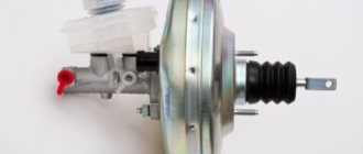
Master brake cylinder (GTC): device and malfunctions
The GTZ is an integral part of the brake system, which performs one of the key tasks - converting the force applied to the brake pedal to generate pressure in the system. The GTZ interacts through the “vacuum valve” rod with the brake pedal directly. The task of the GTZ is to evenly distribute pressure across all circuits.
In the photo: master brake cylinder of VAZ 2110
The brake cylinder is located on the brake “vacuum reservoir” cover. A brake fluid reservoir is mounted above it. The sections of the tank and the GTZ are interconnected by bypass holes, and are responsible for a specific section in the system. The reservoir itself is designed to replenish the loss of “brake fluid”. Visually, the tank has a transparent body, with a scale for monitoring the liquid level. In addition to the scale, sensors installed in the tank are used to signal the liquid level, displaying information on the “tidy”.
Location of GTZ
Types and design of GTZ
Structurally, gas turbine engines are divided into the following types:
For clarity, we will consider the design and principle of operation using the example of double-circuit GTZ. They are more popular than their predecessors. The latter were installed mostly on cars of the last century (various models of Moskvich, Zhiguli, GAZ, GAZ-53, 33 (first modification) trucks, etc. The dual-circuit system is considered more effective in terms of braking. Now it is equipped with Most of the modern cars are both domestic (Lada Kalina, Priora, “Ten” family, “Samar”, Granta, Vesta, Xray) and foreign (Renault Logan, Volkswagen Polo, KIA RIO, Hyundai Solaris, Opel Astra, Vectra, Chevrolet Lanos, Aveo, Cobalt, etc.) The advantages of a dual-circuit brake cylinder system are that if, for example, one circuit fails, the brakes on one pair of wheels are lost, but another circuit remains in the “battle” another pair of wheels, and therefore brakes, of which there are none.
Each of the circuits is responsible for a specific pair of wheels. So, if the car is rear-wheel drive, that is, there is a division, the first circuit is responsible for the front pairs of wheels, the second for the rear ones.
However, if we are talking about a front-wheel drive vehicle, then the distribution of responsibility occurs diagonally: L.P./P. Z. and P.P./L.Z.
The brake master cylinder has two main types:
• With bypass hole directly in the cylinder body.
• With bypass valve in the piston.
GTZ device
GTZ, where bypass valves are installed on the piston, are used for installation on cars with ABS systems. The fact is that in addition to bypass valves, such devices include valves to maintain excess pressure in different circuits, which is especially important when ABS is operating.
To make it clear, pistons are placed one behind the other in the brake cylinder body. The first piston is acted upon by a rod from the brake booster while the second piston is secured, essentially "free" and moved by increasing pressure or "direct" force from the other piston. In order for the pistons to “move” tightly along the cylinder, cuffs are installed at the edges. There is an additional seal in the space between the pistons. In addition, the device includes two springs, a travel stop, locking rings and a plug.
Principle of operation
From the pedal, a force is supplied to the first piston of the GTZ through the “vacuum chamber”, from which it begins to move. When moving, the holes in the cylinder are blocked, thereby increasing the pressure in the current section. Then, due to the pressure of the first section, the second piston begins to move, similarly blocking the hole of its “block”, increasing the pressure in it. When the desired pressure is reached, the machine slows down. Next, the springs “pull” the pistons back. Passing again through the same holes, the pressure decreases to its original value. Excess brake fluid used in operation is returned to the reservoir.
Operating principle of the master cylinder
In cases where there is a leak in the system of one of the circuits, the operation of the unit continues, but with some changes, including operational efficiency. If the leak occurs in the first “compartment,” then the first piston will move until it hits the second. Then, moving together until the plug, they will create pressure in the second “compartment”. But, if there is a leak in the second “block”, then the pressure in the first will not rise until both pistons meet and hit the plug. Only then will the pressure in the primary circuit increase and the brakes will apply.
Signs, malfunctions and resource
Let's talk about the signs and malfunctions of the GTZ. So:
1. Pedal dips. Serious damage is often due to the fact that the pistons do not work and, accordingly, do not generate the required pressure. As a result, the pads (especially if they are drum brakes) cannot compress sufficiently. It requires disassembling the part and purchasing the necessary spare parts or the unit as a whole.
Brake cylinder disassembled
2. Soft pedal. This often indicates that some air has accumulated in the system. The solution is simply simple - you need to bleed the system. To do this, unscrew the relief valve and press the pedal until “clean” liquid, without bubbles, flows out of the holes.
Repair of vacuum brake booster VAZ 2106, 2107, 2108, 2109, 2110
The vacuum brake booster (abbreviated as VUT) of VAZ vehicles makes the driver’s work easier - it enhances the effect of pressing the pedal in the braking system (TS). This unit consists of the following main parts:
- valve;
- metal case;
- diaphragms;
- piston;
- rod;
- powerful return spring;
- a pusher that connects to the brake pedal;
- protective cover;
- flange for installing a check valve.
The body of the device is divided into two halves by a diaphragm, and the master brake cylinder is installed on the side where the vacuum is created. A vacuum (vacuum) is created by connecting this part of the housing to the intake manifold of the internal combustion engine, and when the engine is not running, the channel closes the check valve installed in the VUT flange. Air (vacuum) with the help of a rod and piston when pressing the brake enhances the braking effect, thereby making the driver’s work easier - there is no need to press the pedal with great force. After releasing the pedal, a powerful return spring allows the diaphragm inside the housing to return to its original position. When the engine is turned off, no vacuum is created in the system and the vacuum brake booster does not operate.
On VAZ-2106-07 and VAZ-2108-10 cars, brake boosters are installed that differ in appearance, but the principle of operation of the devices is the same. We check the serviceability of the VUT as follows: press the brake pedal and start the engine - if the pedal “falls” (lowers under the pressure of the foot), the VUT works.
The main problem with a vacuum booster is damage to the diaphragm. When the diaphragm is ruptured, air penetrates from the outer part of the housing into the vacuum cavity, and a vacuum is not created in the device. But the malfunction may not necessarily lie in the device itself - often the VUT does not work due to air leaks or for other reasons:
- the “vacuum” check valve is faulty;
- there is air leakage from the hose connecting the intake manifold to the brake booster;
- there is no compression in the internal combustion engine cylinder where the vacuum comes from.
It should be noted that the vacuum brake booster on VAZ 2106-10 vehicles is connected by a hose to the fourth cylinder of the engine.
Repair of the vacuum brake booster of VAZ 2106, 2107, 2108, 2109, 2110 should begin with the dismantling of this unit, then the VUT must be disassembled.
Tuning the brake system of VAZ-2106
The brake system of a car is the main mechanism responsible for safety on the road. The manufacturer produces cars with a braking system that fully meets all the technical characteristics of the vehicle.
The braking system in the VAZ 2106 is not the strong point of this car, but it can be improved
The exception to the rule is domestic cars that were developed and produced several decades ago. Their braking system does not quite meet modern technological requirements, which is pushing VAZ owners to make drastic decisions. Increasingly, they are improving and modernizing the braking system of vehicles. In this article we will look at how to properly tune the VAZ-2106 brakes in order to improve their performance and safety during vehicle operation.
Removing the vacuum booster 2106-07
Removing the VUT on a VAZ classic car is quite simple, and if you have minimal plumbing skills, this work is not difficult to complete. We remove the unit as follows:
- we turn off the engine, disconnect the main brake cylinder (GTC) from the “vacuum chamber”, the cylinder is held on by two nuts. There is no need to disconnect the brake pipes and hoses from the turbocharger; we simply move the cylinder to the side;
- we pull the hose off the check valve, while holding the valve so as not to pull it out and break it;
- in the cabin, remove the fixing bracket on the brake pedal and release the VUT pusher;
- then in the cabin we unscrew the four nuts that hold the “vacuum unit”, dismantle the unit - it is removed in the engine compartment.
Installation of BSZ on VAZ 2106
When choosing a contactless ignition kit, pay attention to the engine size of your “six”. The distributor shaft for a 1.3 liter engine should be 7 mm shorter than for more powerful 1.5 and 1.6 liter power units
To install BSZ on a VAZ 2106 car, you should prepare the following set of tools:
- open-end or socket wrenches with dimensions of 7-13 mm;
- flathead and Phillips head screwdrivers;
- pliers;
- drill with a 4 mm drill (to mount the electronic unit in the side member you will have to make 2 holes for self-tapping screws).
To drill 2 holes for the switch, you can use a hand drill instead of an electric one
I highly recommend purchasing a 38 mm socket wrench with a long handle for unscrewing the ratchet. It is inexpensive, around 150 rubles, and is useful in many situations. Using this key, it is easy to turn the crankshaft and set pulley marks to adjust the ignition and timing.
With a 38 mm spanner it is very convenient to turn the crankshaft using the ratchet nut
The first step is to dismantle the old system - the main distributor and coil:
- Pull out the high-voltage wires from the sockets of the distributor cover and disconnect it from the body by unlocking the latches.
- When turning the crankshaft, set the slider at an angle of approximately 90° to the engine and place a mark on the valve cover opposite. Unscrew the 13 mm nut securing the distributor to the block.
- Unscrew the clamps of the old coil and disconnect the wires. It is advisable to remember the pinout or sketch it.
- Loosen and unscrew the nuts securing the clamp, remove the coil and distributor from the car.
When removing the ignition distributor, keep the washer-shaped gasket installed between the part platform and the cylinder block. It may be useful for a contactless distributor.
Before installing the BSZ, it is worth checking the condition of the high voltage cables and spark plugs. If you doubt the performance of these parts, it is better to change them immediately. Serviceable spark plugs must be cleaned and the gap set to 0.8-0.9 mm.
Install the contactless kit according to the instructions:
- Remove the BSZ distributor cap and, if necessary, replace the sealing washer from the old spare part. Turn the slider to the desired position and insert the distributor shaft into the socket, lightly pressing the pad with a nut.
- Replace the cover, securing the latches. Connect the spark plug cables according to the numbering (the numbers are indicated on the cover).
- Screw the coil of the contactless system to the body of the VAZ 2106. To ensure that terminals “B” and “K” are in their original position, first unfold the body of the product inside the mounting clamp.
- Place the wires from the ignition switch and tachometer onto the contacts according to the diagram above.
- Install the controller next to the spar by drilling 2 holes. For convenience, remove the expansion tank.
- Connect the wiring harness to the distributor, switch and transformer. The blue wire is connected to terminal “B” of the coil, the brown wire is connected to terminal “K”. Place a high-voltage cable between the distributor cover and the central electrode of the transformer.
If there were no annoying mistakes during the installation process, the car will start immediately. The ignition can be adjusted “by ear” by loosening the distributor nut and slowly turning the housing at idle engine speed. Achieve the most stable operation of the motor and tighten the nut. Installation is complete.
Disassembling vacuum booster 2109
It is not difficult to disassemble VUT 2108-2109, but for disassembly it is necessary to fix the device. We disassemble the node in the following order:
- clamp the “vacuum sealer” in a vice;
- using a screwdriver on the body, we bend the grooves with which the two halves are held together;
- when almost all the rivets are straightened, it is necessary to hold the outer part of the body - a spring is installed inside the device, and it can shoot. If the old diaphragm is put back into place, there is no need to push the screwdriver far inward, as the rubber seal may be damaged;
- remove the rubber covers from the fastenings (2 pcs.);
- dismantle the plastic casing together with the diaphragm and pusher assembly;
Typically, the repair kit for the VAZ-2109 vacuum amplifier contains a diaphragm, a cuff, a boot, covers (2 pcs.) and a valve. All parts should be changed so that you don’t have to redo the work later. When assembling a vacuum amplifier, it is better to immediately fix the diaphragm on a plastic casing, this will make it easier to mount the unit.
Unit repair - diaphragm replacement
This operation is unpopular among Zhiguli owners; usually car enthusiasts prefer to change the entire amplifier. The reason is that the result does not correspond to the effort expended; it is easier to buy and install the VUT assembled. If you definitely decide to disassemble and repair the vacuum amplifier, prepare the following tools and consumables:
- assembly spatula, powerful flat screwdriver;
- pliers;
- hammer;
- brush with metal bristles;
- large bench vice;
- repair kit for vacuum amplifiers VAZ 2103—2107;
- silicone sealant.
To carry out repair work, the VUT must be removed from the vehicle, as described in the instructions above. Disassembly and replacement of parts is carried out in the following order:
- Place a mark on the body with a marker, flare the connections with the cover, bending the edges of the shell with a mounting blade.
- Carefully separate the elements, holding the lid with your hands, as there is a large, powerful spring installed inside.
- Remove the rod and seal, remove the diaphragm from the inner housing. When disassembling, lay out all the parts one by one on the table so as not to confuse anything during the installation process.
- Clean the housing and the membrane contact areas with a brush. If necessary, dry the inside of the chambers.
- Reassemble the vacuum booster elements in reverse order, using new parts from the repair kit.
- Aligning the marks on the cover and body, insert the spring and compress both halves in a vice. Roll carefully using a pry bar, hammer and screwdriver.
- Check the tightness of the VUT using a rubber bulb inserted into the hole in the vacuum hose.
After assembly, install the unit on the car, having adjusted the rod extension in advance (the procedure is described in the previous section). When finished, check the operation of the amplifier while running.
Video: how to change the VUT diaphragm on a “classic”
Vacuum brake boosters rarely bother Zhiguli owners with breakdowns. There are cases when the factory VUT worked properly throughout the entire life of the VAZ 2107. If the unit suddenly fails, there is no need to panic - a malfunction of the vacuum booster does not affect the operation of the brake system, only the pedal becomes hard and uncomfortable for the driver.
Repair of UAZ vacuum brake booster
Problems with the vacuum booster of UAZ vehicles can be identified by the following symptoms:
- the engine suffers, and since on UAZ engines the vacuum hose goes to the manifold of the first cylinder, if the VUT is faulty, this particular cylinder is not completed;
- a hissing is heard under the hood - the diaphragm is poisoning the air;
- the brake pedal is hard and does not press when starting the engine;
- There are wet leaks between the turbocharger and the amplifier (brake fluid is leaking).
If leaks of the brake fluid are detected in the area of the VUT, it is necessary to urgently change or repair the GTZ, but if the liquid has already entered the vacuum booster, most likely the VUT will also have to be repaired.
Another common malfunction in the brake system is failure of the check valve. This simple mechanism is very easy to check - you just need to blow into it. The valve should be blown freely in one direction (when rarefied air is supplied from the manifold), but air flows in the opposite direction with great difficulty. If the valve is faulty, it is blown freely in both directions.
Device
The operating principle of this mechanism is based on the influence of atmospheric pressure of the external environment directly on the discharged area. The device itself looks like a chamber, which is divided into two halves by a special elastic membrane.
Its first part is connected to the atmosphere, and the second is connected to the exhaust manifold of the engine, which creates a lower pressure. Due to different pressures, the membrane bends towards the rarefied air, and part of its energy is transferred to the elements of the car’s braking system.
Replacing VUT on UAZ vehicles
The amplifier is removed on cars produced by the Ulyanovsk Automobile Plant according to the same principle as on VAZ cars. Let's consider replacing VUT using the example of a UAZ-31519 car:
- first of all, we unscrew the two fastenings of the GTZ to the “vacuum”, usually the cylinder is secured with nuts 17, without disconnecting the brake pipes, we move it to the side;
- under the hood, in the area of the windshield, unscrew the 2 bolts of the VUT amplifier bracket, the standard bolts are 14 mm turnkey;
- in the cabin, at the connection of the rod with the brake pedal, pull out the cotter pin; for this you will need pliers;
- remove the connecting pin;
the two lower nuts of the amplifier bracket are located in the car interior, they are turnkey 17, unscrew this fastener;
- pull off the hose from the fitting of the device, dismantle the VUT;
- disconnect the bracket from the “vacuum” - to do this, unscrew the four nuts (they are 17 mm);
- the check valve is not included with the part, so we move it from the old VUT to the new one;
- We connect the bracket to the new amplifier, carry out the assembly - we install all the parts in their places.
Generator VAZ 2106: purpose and functions
A car generator is a small electrical device whose main task is to convert mechanical energy into electrical current.
In the design of any car, a generator is needed to charge the battery and feed all electronic devices while the engine is running. The generator's task is to ensure uninterrupted operation of all electrical systems of the machine and the battery.
How exactly does the generator work on a VAZ 2106? All processes of energy conversion from mechanical to electrical are carried out according to a strict scheme:
- The driver turns the key in the ignition.
- Immediately, the current from the battery through the brushes and other contacts enters the excitation winding.
- It is in the winding that the magnetic field appears.
- The crankshaft begins to rotate, from which the generator rotor is also driven (the generator is connected to the crankshaft by a belt drive).
- As soon as the generator rotor reaches a certain rotation speed, the generator enters the self-excitation stage, that is, in the future, all electronic systems are powered only from it.
- The generator performance indicator on the VAZ 2106 is displayed in the form of a control lamp on the dashboard, so the driver can always see whether the device has enough charge for full operation of the car.
Standard device for the "six"
Design of the G-221 generator
Before talking about the design features of the VAZ 2106 generator, it should be clarified that it has unique clamps for mounting on the engine. On the body of the device there are special “ears” into which studs are inserted and tightened with nuts. And so that the “ears” do not wear out during operation, their internal parts are equipped with a high-strength rubber gasket.
The generator itself consists of several elements, each of which we will now consider separately. All these devices are built into a light-alloy cast housing. To prevent the device from overheating during long-term operation, the case has many small holes for ventilation.
The device is securely fixed in the engine and connects to various car systems
Winding
Due to the fact that the generator has three phases, windings are installed in it immediately. The purpose of the windings is to generate a magnetic field. Of course, only special copper wire is used for their manufacture. However, to protect against overheating, the winding wires are covered with two layers of heat-insulating material or varnish.
Thick copper wire rarely breaks or burns out, so this part of the generator is considered the most durable
Relay regulator
This is the name of the electronic circuit that controls the voltage at the output of the generator. The relay is necessary to ensure that a strictly limited amount of voltage reaches the battery and other devices. That is, the main function of the relay regulator is to control overloads and maintain an optimal voltage in the network of about 13.5 V.
A small plate with built-in circuitry to monitor the output voltage
Rotor
The rotor is the main electric magnet of the generator. It has only one winding and is located on the crankshaft. It is the rotor that begins to rotate after the crankshaft starts and gives movement to all other parts of the device.
The rotor is the main rotating element of the generator
Generator brushes
The generator brushes are located in brush holders and are needed to generate current. In the entire structure, it is the brushes that wear out the fastest, since the main work of generating energy falls on them.
The outer side of the brushes can quickly wear out, which is why there are interruptions in the operation of the VAZ 2106 generator
Diode bridge
A diode bridge is most often called a rectifier. It consists of 6 diodes that are placed on a printed circuit board. The main job of a rectifier is to convert alternating current into direct current to maintain stable operation of all electronic devices in the car.
Due to its specific shape, drivers often call the diode bridge a “horseshoe”
Pulley
The pulley is the driving element of the generator. The belt is tensioned simultaneously on two pulleys: the crankshaft and the generator, so the operation of the two mechanisms is continuously interconnected.
One of the generator elements
Features of repair of UAZ vacuum amplifiers
Unlike the vacuum amplifiers of VAZ cars, the VUT housing on UAZ cars is very durable, and it is not at all easy to halve it. You can bend the protrusions using a pry bar and a hammer, but this way the work is done in violation of the technology - according to the instructions, you need to rotate one half relative to the other. The biggest problem during disassembly is the “halving” of the body - sometimes these parts boil so much that it is impossible to disassemble the assembly. Car owners are advised not to press one body into another under any circumstances - then turning will definitely not work.
Another problem in repairing “vacuum units” is the low quality of spare parts in the repair kit; sometimes the installed parts are not enough for six months. Motorists advise not to do repairs, but to buy a new spare part, although there is another disadvantage - VUT for cars like UAZ-469 or UAZ-452 is not cheap, about 3 thousand rubles. As an option, you can pick up a “vacuum” from a foreign car at a car disassembly shop, whose mountings fit the main brake cylinder, and install it on the car by fitting it. The result is cheaper and more reliable - imported parts, even in used condition, last for several years without any complaints.
Absolute vehicle malfunctions
During operation, the braking functions of the system deteriorate. This is due to wear and tear of components, assemblies and parts that require repair. Some vehicle malfunctions are included in a special “List...”, and driving with them is prohibited.
Inefficiency of the working vehicle
The most common malfunction of the brake system (including the VAZ-2107) is inefficiency, which is diagnosed by two main parameters (when carrying out a specialized instrumental study):
- increasing braking distance;
- increase in steady deceleration during braking.
Such faults can be determined by eye. After driving a passenger car on a dry road at a speed of 40 km/h, when braking, the car travels a distance exceeding 12.2 m. In this case, according to paragraph 2.3.1 of the traffic rules, the use of the vehicle is prohibited (even to the parking or repair site) . This malfunction may be due to:
- presence of air in the system;
- fluid leakage from the system;
- worn out pads;
- failure of the main or wheel cylinders.
In other words, almost the entire vehicle should be subject to monitoring. Repair (replacement) of components and assemblies will require bleeding the system to remove air from it.
Leakage of the working vehicle
During vehicle operation, components, assemblies and parts are subject to wear, which leads to depressurization of the system and leakage of brake fluid. This most often occurs in brake hoses or wheel cylinders. Fault repair is carried out by monitoring leaks and replacing damaged elements.
Leakage of the system also excludes the possibility of operating the car (according to paragraph 2.3.1 of the traffic rules).
Ineffective parking vehicle
This defect is the most common when the car moves involuntarily even with the handbrake locked. This is due to wear on the pads, discs or drums, as well as stretching of the cable elements.
According to the requirements of the “List...”, a parked vehicle must ensure that the passenger car is stationary:
- on a slope of up to 16% at full load;
- on a 23% slope when equipped.
In the event that these requirements are not met, the vehicle can only be driven to a parking or repair site. Repair of the malfunction is ensured by adjusting the cable tension with a special nut or replacing worn parts.
Adjusting the rod of the vacuum brake booster UAZ
Often, after replacing the VUT, problems appear, and the car no longer brakes as well as it did before with a working “vacuum system” - the brake pedal takes off at the very end, or the system does not fully release the brakes. The whole point here is the rod that presses on the GTZ piston - it may not be adjusted from the factory. This rod has an adjusting screw, which is secured with a locknut. On UAZ cars (we don’t take the “Patriot” model into account), we check the rod adjustment as follows:
- push the rod all the way back;
- take a metal ruler or feeler gauge to adjust the valves and lay it along the body;
- We measure the protrusion above the body with a caliper - the rod should extend approximately 7.8-8.0 mm;
- if this distance does not correspond to the norm, loosen the lock nut and use the adjusting screw to increase or decrease the length of the rod;
- Having established the desired size, fix the screw with a lock nut.
Even on the UAZ Hunter, the pedal can “take” at the very end, and it has a large free play. It is necessary to pay attention to the position of the pedal - if it is too low from the floor in the cabin, it needs to be adjusted:
- unscrew the brake light mounting nuts on the brake pedal;
- disconnect the wires from the brake light sensor;
- Use two 19 mm nuts to raise the pedal, press the brake to check the free play, and if the pedal is adjusted normally, tighten the nuts.
Troubleshooting
The first sign of loss of vacuum booster seal is not deterioration of the brakes, as many sources on the Internet describe the malfunction. When air just begins to leak through the leaky membrane, the VUT continues to function properly, since the motor manages to maintain a vacuum in the front chamber. The first symptom is changes in the operation of the engine itself:
- due to air leaks into the third cylinder, the engine begins to “trouble” at idle;
- crankshaft revolutions “float”, the stronger the suction, the greater the amplitude of oscillations;
- a running engine reacts to the brake pedal and stalls when pressed sharply;
- Gasoline consumption increases.
Air leaking into the engine through the VUT causes the third cylinder to turn off - the engine begins to “trouble.”
If the car owner ignores the primary symptoms, the situation gets worse - the pedal becomes harder and requires more physical effort to slow down and stop the car. The car can be used further; a breakdown of the VUT does not lead to a complete failure of the brakes, but it significantly complicates driving, especially if you are not used to it. Emergency braking will become a problem.
How to make sure that the vacuum booster is leaking:
- Loosen the clamp and remove the vacuum pipe from the fitting on the manifold.
- Plug the fitting with a tight homemade plug.
- Start the engine. If the revs level out, the problem clearly lies in the amplifier.
- Remove the high voltage wire and remove the spark plug for cylinder III.
If the VUT fails, the electrodes will be smoked with black soot. If soot is observed on the spark plug of cylinder III, and the remaining spark plugs are clean, you need to check the condition of the vacuum brake booster
Whenever possible, I use the old “old-fashioned” method - I simply pinch the vacuum hose with pliers while the engine is running. If the third cylinder starts working and idle speed is restored, I proceed to checking the brake booster.
Similarly, the problem can be temporarily fixed while on the road. Disconnect the pipe, plug the fitting and calmly go to the garage or service station - the power unit will operate smoothly, without excessive fuel consumption. But remember, the brake pedal will become hard and stop responding instantly to light pressure.
Additional diagnostic methods:
- Press the brake 3-4 times and start the engine while holding the pedal. If it does not fail, the valve has probably failed.
- With the engine not running, disconnect the hose from the fitting, remove the check valve and firmly insert a pre-compressed rubber bulb into the hole.
On a sealed amplifier it will retain its shape, on a faulty amplifier it will fill with air. To check the tightness of the amplifier and the functionality of the check valve, you can use a rubber bulb
Using a bulb, you can accurately determine the location of the defect, but the vacuum booster will have to be removed. While pumping air into the chamber, wash the edges of the joints and the stem seal - bubbles will indicate the location of damage.
Adjusting the GTZ gazelle rod
Message by Catmaps » Fri Mar 13, 2015 15:30 pm
I finally installed this device on my 24-10. The idea of replacement had been in my head for a long time, but what prompted me to take action was that the brake pedal became difficult to return, and the lower the temperature, the lazier it returned. Despite the fact that the bushings in the rods from the pedal to the amplifier were recently changed and lubricated. There were two options for replacement: either the ADS and the old master cylinder or the amplifier + BOSCH GTZ from Business. Why exactly two options, and not 5-10? They're all just NEW! I’m somehow used to installing new parts on my cars, I’ve played enough with old ones both with our cars and with foreign ones, naturally, if there is no alternative, then a bulkhead. Well, that's it, a slight digression from the topic.
Having studied the Internet and read reviews on the installation and operation of the device itself, by the way, there are not so many of them and everything is not described very smoothly, I decided to install BOSCH, it is still a foreign product, well, with GTZ, and mine has already worked for 24 years. VUT can be installed without any major modifications on all cars with VUT (sorry for the tautology), i.e. where on the engine shield there is a VUT mounting bracket. So, for trouble-free implementation, the following details are needed: 1. The VUT itself with the Gazelle business GTZ - BOSCH 0 204 702 834, also known as 3302-3510008-20 - 1 pc. 2. VUT bracket (adapter) - 3302-3510162 - 1 pc. 3. Check valve - 31029-3552010 or 2103-3510045 - 1 pc. 4. Adapters for tubes from thread M10x1.0 to M10x1.25 - WP R-137 - 2 pcs. (BOSCH has an M10x1.0 thread like on foreign cars, we have M10x1.25) If desired, you can replace all the plastic bushings in the pedal drive rods and the vacuum hose: 5. Brake pedal axle bushing - 13-3504023 - 6 pcs. (clutch pedal in addition) 6. Pusher axle bushing - 21-3504039 - 8 pcs. (clutch pedal in addition) 7. Vacuum booster hose - 21213-3510050 (I installed this one because it is the longest ready-made) To connect the fluid level sensor you need: 8. Connecting block for the brake and coolant level sensor 2108-21099 , 2110 - 9025SBP Those who especially wish can, instead of pipe adapters WP R-137, make or re-roll the brake pipes themselves: 9. Brake pipe tip M10x1.0 - WP Z105 10. Brake pipe tip M10x1.1.25 - WP Z112 11. Copper tube diameter 4, 75 - WP or another By the way, WP has a bunch of tips and adapters, you can sculpt anything https://www.pwpnet.pl/index.php?l=ru I twisted the pusher ear from an old VUT.
The VUT itself looks beautiful, the size is the same in length, but slightly larger in diameter. There is one point in the location of the fixed VUT, the bracket (hereinafter referred to as “adapter hardware”) is not symmetrical, and the VUT rod is not located in the center relative to the mounting holes on the bracket of the engine shield (“center”).
I installed the “adapter piece” differently from the way it should be on the Gazelle, I turned it 180 degrees, i.e. The VUT has become shifted relative to the “center” to the right (relative to the movement). In this position, the VUT does not rest against the engine splash guard and there is no need to bend or tap anything, but it becomes necessary to ensure the straight movement of the VUT rod; misalignment is not good and also the plastic pusher bushings will wear out quickly. To do this, I slightly bored out the holes in the engine shield bracket and placed two washers between the ear and the pusher, one simple and the other a Grover.
If the “adapter piece” is screwed on as it should, the VUT will rest against the mudguard and you will need to crush it, then not only that, the VUT rod will rest against the pusher and they will again need to be aligned somehow.
And you also need to remember to screw the pusher ear onto the VUT rod correctly, as it is written in the smart book.
I assembled everything, filled the brake fluid with LM DOT4, and bled it. It took almost 1 liter of brake fluid. Well, what can I say about work? the pedal is so soft and soft, and of course the effort cannot be compared, now you just touch the pedal and the car stops. The only thing I want is even less pedal travel, but I’m probably completely crazy already
In terms of finances, the breakdown is as follows (December 2014 - January 2015): VUT and adapter - 4500 RUR Valve, hose, bushings - 300 RUR Adapters and tips 6 pcs. - 200 re.
GTZ VAZ 2110 signs of malfunction, purpose of the device, performance check replacement
Despite the fact that these two units are inextricably linked with each other, in our material we will consider them separately.
This will allow you to understand in detail all the nuances and features of the operation and repair of the two devices. I – main cylinder body; 2 – low pressure sealing ring; 3 – drive piston of the “left front-right rear brake” circuit; 4 – spacer ring; 5 – high pressure sealing ring; 6 – pressure spring of the sealing ring;
7 – spring plate; 8 – piston return spring; 9 – washer; 10 – locking screw;
II – drive piston of the “right front-left rear brake” circuit; 12 – connecting sleeve; 13 – tank; 14 – brake fluid emergency level sensor; A – gap
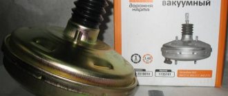
Vacuum booster
The braking system of a car certainly cannot be called perfect, so it has to be supplemented with devices that help improve efficiency. One of them is a vacuum booster.
Application and purpose
Today, a vacuum amplifier is in great demand because it is highly efficient.
Its tasks are extensive, but the amplifier copes with them all perfectly:
- The degree of resistance of the brake pedal increases;
- Reduces the load on the brake system;
- Acts as a highly efficient auxiliary unit;
- Has a positive effect on the service life of the brake system, etc.
This element has the following components:
- Dense body, for the manufacture of which a high-strength polymer is used;
- The diaphragm, which is also called the collecting node;
- Monitoring or control specialized valve;
- Pusher. It allows you to return the engine elements to their original position when there is no power;
- Main piston rod of the brake system cylinder (main);
- Switch return spring.
The body of this spring has two cellular divisions, which are divided into vacuum and atmospheric. Cells are often called chambers.
- The vacuum chamber is a cell directly connected to the brake master cylinder.
- The atmospheric chamber is a cell located opposite the brake pedal. Its open part of the body rests on the brake pedal.
It is also worth noting the diaphragm, which performs two very important tasks:
- Corrects the position of the piston in space;
- Pumps brake fluid to the main brake cylinders.
Installing a vacuum booster involves a serious change in the sensitivity of the pedal, so it is strongly recommended not to apply a large and sudden force to it in the “first couple”. Pressing should be done carefully and smoothly.
Malfunctions and ways to check them
It is possible that you may need to replace the vacuum booster on your VAZ 2110. The cause may be various malfunctions, the characteristic symptoms of which are as follows:
- When you press the brake pedal, a hissing noise occurs, and at the same time, the engine speed often increases;
- The car starts to shake;
- Spark plugs stop working efficiently;
- Fuel consumption increases noticeably.
Before replacing the vacuum booster on a VAZ 2110, it should be checked.
This procedure is performed as follows:
- As with normal bleeding of brakes, with the engine not running, press the gas pedal several times;
- After 5 or 6 presses, keep the pedal in the down position, resting it on the floor, and start the engine;
- After starting, the pedal itself will move forward a little.
There is also a high probability of damage to the diaphragm, on which a hole is formed over time. You can purchase the diaphragm with a repair kit, the cost of which is no more than 500 rubles.
Replacement
To replace an element, you need to understand the main issue - how to remove the vacuum booster from a VAZ 2110. Directly replacing the old element with a new one will not be difficult, just like the reassembly process.
Therefore, we will tell you about the main thing - dismantling the amplifier. Let's start with the fact that the procedure is not complicated, but it requires accuracy and sequence of steps. If you follow the recommendations, the work will take little time and will not take much effort.
- Disconnect the block with wires, which includes brake fluid level sensors in its design.
- Hold the booster check valve with one hand and carefully disconnect the hose with the other. It is advisable to disconnect the hose with a strong hand, since this will require a lot of force.
- Remove the two bolts connecting the booster and master cylinder.
- Carefully remove the cylinder from the amplifier.
- There is no point in disconnecting the brake lines.
- Give access to the dashboard, which will allow you to unscrew the nuts holding the brake pedal bracket. There should be 4 of them.
- It is recommended to dismantle the bracket and amplifier through the engine compartment, since there is enough free space for such manipulations.
- Remove the pin lock plate. To do this, pry the finger with a screwdriver and squeeze it out.
- Now you can easily disable the brake pedal and booster.
- To disconnect the amplifier and bracket, you will have to unscrew the two nuts on the mount.
- A new one is installed in place of the dismantled old vacuum amplifier, and the reassembly procedure is performed in strict sequence of the dismantling process.