In a car, the adsorber absorbs fuel vapor from the gas tank ventilation system and supplies it to the intake, because according to environmental standards, the gas tank must be isolated from the atmosphere.
From Wikipedia ;
Adsorber (from Latin ad - on, with and sorbeo - absorb) is a device for absorbing (thickening) a surface layer of a solid, called an adsorbent (absorber), of dissolved or gaseous substances, not accompanied by a chemical reaction. The adsorber is used in chemical, oil refining and other industries. The process occurring inside this apparatus is called adsorption.
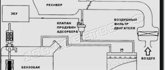
Gasoline vapor filtration system. The diagram is quite conventional, but it reflects the essence. Gasoline vapor from the tank passes through a carbon filter, is cleaned and supplied to the inlet through a solenoid valve controlled by the ECU.
Now the first question is - why filter gasoline vapors if they still go into the intake? The answer is simple - adjusting the internal combustion engine control program by adding the nth number of clean air at the inlet is much easier than making adjustments based on the fuel-air mixture (gasoline vapor from the tank) of an unknown proportion.
And now the answer to the main question - why delete it? So, although some manufacturers claim that this device will have enough resources for the entire life of the car, we know that they are lying)
In general, over time, the adsorber becomes clogged and stops passing air. As a result, we get excess pressure in the tank, which interferes with the normal operation of the fuel pump. In the cabin (sometimes under the hood) we get a periodic smell of gasoline, the vapors of which are squeezed out of the ventilation tube. And the engine starts running on a rich mixture due to lack of air.
Now guess how our country solves this problem? That's right, most people simply throw out the adsorber and turn off the system as shown in the diagram:
A fuel filter from a carburetor classic is usually placed on the tube from the gas tank, and the solenoid valve, through which clean air should flow into the engine, is simply shut off with a bolt.
In the picture I already wrote that this is wrong and here’s why. This method of removing the adsorber only partially solves the problem. Yes, the smell of gasoline disappears, the tank is ventilated, but no air is supplied to the intake and the engine continues to run on a rich mixture.
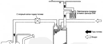
And now the following diagram:
And now it already shows how it SHOULD be done. The same filter from the classics is put on the hose from the valve to the adsorber, which now serves as an air filter and prevents dirt from getting into the receiver. This is how the fuel-air mixture is brought to normal parameters.
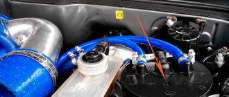
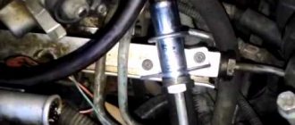
Well, now a couple of visual photos of what it all really looks like:
Everything is clear here, one tube goes to the gas tank, the second through the valve to the engine.
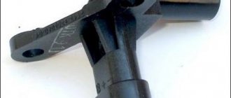
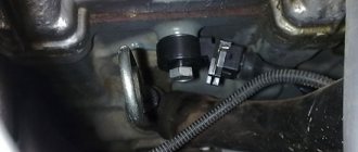
Bottom part of the adsorber. There is a fitting for supplying air from the atmosphere so that a vacuum is not created in the adsorber.
So this is all done on my machine. I didn’t take a photo of the tube from the tank, it’s hard to get to it even without a phone
» How to remove
Gasoline vapor recovery system VAZ 2110 injector
The article is educational in nature and may contain errors; it is recommended for car enthusiasts with a poor understanding of the adsorber.
The article is written in relatively simple words for better understanding
1) What is an adsorber
Adsorber or aAdsorber are often confused - the correct word is “adsorber”... A container with activated carbon, most often looks like a barrel (cylinder) with inlet and outlet hoses
Let's start with the definitions:
Sorption (from Latin sorbeo - absorb) - absorption by a solid or liquid of various substances from the environment. Adsorption is the accumulation of something on the surface of a sorbent. Adsorber (from Latin ad - on, with and sorbeo - absorb) - a device for absorbing dissolved or gaseous substances (fuel vapor) by a surface layer of a solid, called an adsorbent (activated carbon), not accompanied by a chemical reaction Gasoline vapor recovery system (EVAP) — Evaporative Emission Control) is designed to prevent the leakage of gasoline vapors into the atmosphere.
3) Euro-2 and Russia-83
The question arises: why are there no adsorbers on cars with Russia-83 standards, but on cars with Euro-2 and higher standards there is one?
Let's compare two cars - VAZ 21083 and VAZ Priora, namely the power system: VAZ 21083:
Through the drain hose (15), the tank is connected to a separator (19), which traps gasoline vapors. The condensate from the separator is drained back into the tank. The separator communicates with the atmosphere through a two-way valve (21), which prevents excessive increase or decrease in pressure in the fuel tank. The filler neck is connected to the tank with a gas-resistant rubber hose secured with clamps. The plug is sealed.
Those. When the pressure in the fuel tank increases or decreases, gasoline vapors are released into the atmosphere.
Fuel vapors that have passed through the tube from the tank into the separator (16) are partially condensed in it. The condensate from the separator is drained back into the tank through a tube. A gravity valve is installed in the upper part of the separator, which prevents fuel from leaking out of the tank when the vehicle rolls over. Fuel vapors accumulate in the adsorber (1) through the gravity separator valve and the tube connected to it in the adsorber (1) when the engine is not running. When the engine is running and other necessary conditions, the valve (14) communicates with the adsorber cavity with the throttle assembly - and the sorbent is purged: gasoline vapors are mixed with air and discharged through the throttle assembly into the intake manifold and further into the engine cylinders.
Those. Fuel vapor accumulates in the adsorber, during engine operation it is purged by the valve and enters the receiver, and then into the engine itself to burn out.
Lada Priora Hatchback ✤ℨℰȴеℋÅЯ МОШℵИЯ!!! › Logbook › The main thing about the pressure in the fuel system.
Fuel pressure in the car system is one of the important parameters that is used in engine diagnostics. The behavior of the car in various operating modes depends on the pressure. How to measure the pressure in the fuel system with your own hands
For example, buy a device to check fuel pressure. A kit with a fuel pressure gauge, adapter and drain will cost you 1400-1500 rubles. Pay 300-400 rubles to the service station and take measurements there. You can also measure the pressure in the fuel system with an air pressure gauge, which is used to measure tire pressure. Here at this point in more detail. Let's take the example of the tenth VAZ 2110 family. Otherwise, the procedure is similar to any other car. The peculiarity of pressure gauges is that their initial scale values have relative inaccuracy. What does it mean. If the air pressure gauge has a scale of up to 16-20 atm (when the measurement limit for fuel is 5-7 atm), then pressure measurements will not be accurate due to this error, which will fall within the initial values of the instrument scale. Therefore, it is correct to check the fuel pressure with a fuel pressure gauge with a limit of 6-7 atm.
We take a pressure gauge and wrap a piece of foam (plumbing flax) under the pipe and put on an oxygen hose with an internal diameter of 9 mm. Secure with clamps. Place a rag on the generator (so as not to start a fire under the hood). Unscrew the plastic cap on the fuel rail.
put the hose on the pressure gauge
Under the cap there is a hole with a nipple. Unscrew it from the wheel cap. Due to the residual pressure in the rail after removing the nipple, gasoline will splash out.
If desired, you can relieve the pressure in the vehicle's fuel system. To do this, you need to remove the fuel pump fuse and wait until the running car stalls.
We put the second end of the hose on the ramp hole and secure it with a clamp. We remove the rag from the generator and start the engine. Don’t forget to cover the generator with a rag again before removing the hose from the ramp. That's it, now you know how to check the pressure in the fuel system in the field.
attach the hose with pressure gauge to the fitting
check the fuel pressure in the system
By the way, instead of clamps, you can use the classic adjusting bolt bushing. It screws perfectly onto the ramp fitting. To seal, we put a suitable rubber ring on the fitting. On the other side of the bushing we solder a fitting onto which we put a hose with a pressure gauge.
What pressure should be in the VAZ 2110 fuel system? 2.8–3.2 bar (2.8–3.2 atm)
How to measure fuel pressure in a system where there is no return? On VAZ 2110 with 1.6 liter engines, the pressure in the ramp is constant and amounts to 3.6-4.0 atm. Otherwise, the measurement technique is similar. Alternative ways:
It is measured at the outlet fitting of the fuel pump module - this is the one with one tube. You will need a flexible gas-resistant hose with an internal diameter of about 8 mm and a pressure gauge (you need to remove the tube and put on a hose with a pressure gauge instead). The pressure should be 5-7 atm. Close the return line, as is done on an internal combustion engine with a drain ramp, but you must turn it off again at the fuel pump itself. We pull off the second hose (double) and insert a plug into the removed hose, made, for example, from an old fuel filter (saw off the nipple from it and plug it). A single hose must be put on the pump fitting, and now the measurement must be made at the fuel rail. According to the power system diagram, everything will be clear.
Adsorber VAZ 2112 16 valves signs of malfunction
It seemed like such an inconspicuous element, which at first glance is not important for the car, but without which it cannot work properly. Dips appear, the engine “troubles” and the gas tank may even collapse! And all this is due to a faulty adsorber valve. Many people don’t know what it is, how it works and MOST IMPORTANTLY what it affects. Today I will try to put everything into simple terms and describe the main symptoms of a malfunction. It will definitely be useful, so read - watch... ARTICLE CONTENTS
First, let's start with a definition.
An adsorber (from Latin sorbeo - absorb) is a car system that serves to capture gasoline vapors that come out of the tank. When the engine is running, they are sent to the fuel injection system, namely the intake manifold . When the engine is turned off, some of the vapors are captured by the separator (it directs them back to the tank), and the remaining vapors enter the adsorber, where they are neutralized.
Unit performance characteristics
An injector is a device that mixes air and fuel flows in a ratio of 14 to 1. The more accurately this happens, the higher the power of the vehicle engine. The running performance of the “iron horse” depends on the ratio of atmospheric pressure of the surrounding air and vacuum. Sensors that monitor engine parameters of VAZ 2112 and 2110 help optimize fuel injection.
There is a ramp on the intake manifold where the mixture of air and fuel is localized. Pumping from the fuel tank is carried out by a fuel pump operating on an electric drive. In ideal condition, the VAZ 2112 engine is characterized by tightness, ensuring the proper level of pressure in the system. The second important element of the system is the throttle valve.
Under normal conditions, the mentioned element is responsible for the amount of gasoline supplied to the VAZ 2110 engine. The fuel supply system includes:
- a gasoline pump, which is driven by the engine rotor;
- tank;
- filter;
- tubes;
- ramp in the motor;
- flexible pipes;
- throttle assembly;
- sensor circuit (located between the filter and the throttle).
It is possible to understand exactly what is different between the VAZ 2110 engine and a later model with an injection system only after a detailed inspection. From a constructive point of view, the new and flock shapes of the “heart” of the car are no different. Inconsistencies appear at the level of small details. For example, a VAZ 2112 or 2110 engine has exactly 8 valves. Don't overlook the thermostat.
An injection engine is characterized by the presence of a large number of parts that often fail. It is during preventive inspections that the thermostat with an injection form of fuel injection is necessarily checked. If the motor is not regularly inspected, the likelihood of prolonged downtime due to breakdown increases.
Why was the adsorber created?
Actually, this is a tribute to the environmental standard, namely EURO-2. Essentially this is a large filter that catches light hydrocarbons. According to the new standards, it is unacceptable for gasoline vapors to enter the atmosphere, because this contributes to air pollution.
Also, couples should not enter the car interior, because this is, to put it mildly, harmful! ON old carburetor cars, such a filter and its valve simply did not exist; the system there is a little different. BUT the carburetor went away along with the old standards, now there is only an injector and a filtration system is MANDATORY.
And now in more detail
How can I check the functionality of this device? The fundamental element in the absorber is the valve. To understand the function, let’s look at how the adsorber works. When a car is parked, a huge amount of gasoline vapor can accumulate in its tank. Some of the vapor is caught by the recuperator, and the rest settles back into the tank. The part that was caught goes into the adsorber. When the engine is running, the absorber valve closes and interrupts the access of vapors, now they are sent to the combustion chamber. What is it for? When you start the car, our device prevents vapors from entering the exhaust manifold, thereby reducing the amount of harmful substances in the gas.
How to get rid of the smell of gasoline
To understand where the smell of gasoline may be coming from in your car, you should study the car's fuel supply diagram. Let's look at the example of a car of the tenth family: 1 - injectors; 2 — fitting plug for monitoring fuel pressure; 3 — injector ramp; 4 — bracket for fastening fuel pipes; 5 — fuel pressure regulator; 6 — adsorber with solenoid valve; 7 — hose for suction of gasoline vapors from the adsorber; 8 — throttle assembly; 9 - two-way valve; 10 - gravity valve; 11 - safety valve; 12 - separator; 13 — separator hose; 14 — fuel tank plug; 15 - filling pipe; 16 — filling pipe hose; 17 — fuel filter; 18 — fuel tank; 19 — electric fuel pump; 20 — fuel drain line; 21 - fuel supply line.
Osipov Mikhail, VAZ 2112, Toyota Camry, driving experience 11 years.
Hi all! My name is Mikhail, now I’ll tell you a story about how I managed to exchange my two-wheeler for a 2010 Camry. It all started with the fact that I began to be wildly irritated by the breakdowns of the two-wheeler, it seemed like nothing serious was broken, but damn it, there were so many little things that really started to irritate me. This is where the idea arose that it was time to change the car to a foreign car. The choice fell on the melting Camry of the tenth years.
Yes, I had matured morally, but financially I just couldn’t handle it. I’ll say right away that I am against loans and taking a car, especially not a new one, on credit is unreasonable. My salary is 24k a month, so collecting 600-700 thousand is almost impossible for me. I started looking for different ways to make money on the Internet. You can’t imagine how many scams there are, what I haven’t tried: sports betting, network marketing, and even the Vulcan casino, where I successfully lost about 10 thousand ((The only direction in which it seemed to me that I could make money was currency trading on the stock exchange, they call it Forex. But when I started delving into it, I realized that it was very difficult for me. I continued to dig further and came across binary options. The essence is the same as in Forex, but it’s much easier to understand. I started reading forums, studying trading strategies. I tried it on a demo account, then opened a real account. To be honest, I didn’t manage to start earning money right away, until I understood all the mechanics of options, I lost about 3,000 rubles, but as it turned out, it was a precious experience. Now I earn 5-7 thousand rubles a day. I managed to get the car buy after half a year, but in my opinion this is a good result, and it’s not about the car, my life has changed, I naturally quit my job, I have more free time for myself and my family. You’ll laugh, but I work directly on the phone)) If If you want to change your life like me, then here’s what I advise you to do right now: 1. Register 2. Practice on a Demo account (it’s free). 3. As soon as you get something on the Demo account, top up your REAL ACCOUNT and go to REAL MONEY!
Which is better: carburetor or injector?
And now a little about which VAZ-2110 engine will be more reliable: an injector or a carburetor? But you need to look at this issue from different angles. For example, beginners will like the injector. Constant speed, there is no need to shut off the air supply in cold weather, and starting off is much easier. But there is another advantage - the car is more responsive at high speeds. Even at a speed of 120 km/h, when you press the gas pedal, the car quickly picks up speed. With carburetor engines this happens much more slowly. Therefore, overtaking in a car with an injector is safer. But when starting from a traffic light, the carburetor will easily “break” the injector. And the reason is higher torque at the bottom. And the cost of maintenance, of course, is higher for injection “tens”, since sometimes it is not easy to make an accurate diagnosis in the event of a breakdown.
Surprise: Husbands Want Their Wives to Do These 17 Things More Often If you want your relationship to be happier, you should do the things on this simple list more often.
11 Weird Signs That You're Good in Bed Do you also want to believe that you please your romantic partner in bed? At least you don't want to blush and apologize.
15 Cancer Symptoms Women Most Often Ignore Many signs of cancer are similar to symptoms of other diseases or conditions, which is why they are often ignored.
Pay attention to your body. If you notice
7 Body Parts You Shouldn't Touch with Your Hands Think of your body as a temple: you can use it, but there are some sacred places that you shouldn't touch with your hands. Research showing.
13 signs that you have the best husband Husbands are truly great people. What a pity that good spouses don't grow on trees. If your significant other does these 13 things, then you can s.
These 10 little things a man always notices in a woman Do you think your man doesn’t understand anything about female psychology? This is wrong. Not a single little thing can be hidden from the gaze of a partner who loves you. And here are 10 things.
Components
In fact, this is a large plastic jar with activated carbon inside, because it is this composition that perfectly fights gasoline vapors. The main parts can be described as follows:
As you can see, there is absolutely nothing complicated. Separator - serves to catch part of the gasoline, then sends it back to the tank. Gravity valve - almost never used, but it is needed in emergency situations, for example during accidents, it prevents fuel from overflowing from the tank (for example, when a car overturns).
The pressure sensor is a very necessary thing - it monitors the pressure of gasoline vapors inside the tank, if necessary, it opens and resets it, preventing the structure from being damaged.
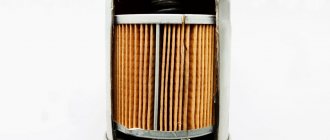
The filter part is, as I wrote above, a large jar into which coal powder is poured, in fairly large granules. This is done so that vapors can pass and condense freely.
Connecting tubes are needed to connect all the main parts, filters, sensors and valves, I think this is clear.
Solenoid valve - used to switch modes for capturing gasoline vapors, we will talk about it in more detail below.
Checking the functionality of the adsorber
To make sure that the malfunction is related specifically to the valve of this element, you can send the car for a full diagnosis. But this is expensive, so let’s first try to identify possible problems ourselves.
First of all, you need to see if the controller is generating errors, for example, “open circuit control.” If everything is fine, then it will use a manual check. To do this, just prepare a multimeter, a screwdriver and several wires. After this you need to follow a few simple steps:
- Raise the hood of the car and find the valve you need.
- Disconnect the wiring harness from this element. To do this, you must first release the special lock that secures the pad.
- Check if there is voltage going to the valve. To do this, you need to turn on the multimeter and switch it to voltmeter mode. After this, the black probe of the device is connected to the ground of the car, and the red probe is connected to the connector marked “A”, which is located on the wiring harness. The next step is to start the engine and see what readings the device gives. The voltage should be the same as the battery. If it is not there at all or is too small, then you will probably have to look for a more serious problem. If everything is fine with the voltage, then you can move on to the next step.
- Remove the purge valve. To remove it you need to use a screwdriver to slightly loosen the clamps. After this, you can easily move the valve slightly up and smoothly pull it out along a small bracket. After this, the device must be connected directly to the battery terminals. One wire goes to the purge valve (to “+”), and the second is connected to “minus”. After this, both conductors are connected to the corresponding battery terminals. If there is no click, then the valve is completely out of order and it is best to replace it.
Removing the absorber
The unit is located in the front right compartment of the engine compartment, removal begins with:
Loosen the clamps and remove the pipes (hoses)
We remove the unit after loosening the tightening clamp
The independent replacement is completed, all you have to do is watch the video and get to work, there is nothing difficult about replacing, just decide for yourself whether the environment is important to you or not.
How to check the adsorber valve
A specific question is how to check the operation of the adsorber valve? This device is found on a huge number of new cars. It is designed to absorb excess carbon gases from the car's gas tank. Thus, this mechanism prevents the release of gases into the atmosphere. It was necessary to use a device of this type after the introduction of new restrictive standards Euro-3 and higher. When working properly, the car has a low level of pollutant gases in the exhaust, and there is also an at least insignificant decrease in fuel consumption. But, like any device, this motor element also tends to break. Failure can occur due to clogging of the adsorbent inside the absorber, also due to a specific mechanical effect on the absorber body. In any case, difficulties begin when the engine operates...
First, a little definition.
The adsorber valve is actually located on a can that has activated carbon inside, it is actually installed in the gas tank (or nearby, maybe in the power system) and absorbs excess gasoline vapors. This “can” absorbs them, condenses them and sends them back to the power system. But for proper and long-term operation it must be ventilated.
Characteristics of the VAZ 2110 injector 8 valves with a working volume of 1.5 and 1.6 liters.
• Engine VAZ 2111 1.5 l. 8-valve injector ➤ Displacement – 1499 cm3 ➤ Number of cylinders – 4 ➤ Number of valves – 8 ➤ Cylinder diameter – 82 mm ➤ Piston stroke – 71 mm ➤ Power – 76 hp (56 kW) at 5600 rpm ➤ Torque - 115 Nm at 3800 rpm ➤ Compression ratio - 9.9 ➤ Power system - distributed injection ➤ Acceleration to 100 km/h - 14 seconds ➤ Maximum speed - 167 kilometers per hour ➤ Average fuel consumption – 7.2 liters • Engine VAZ 21114 1.6 l. 8-valve injector ➤ Displacement – 1596 cm3 ➤ Number of cylinders – 4 ➤ Number of valves – 8 ➤ Cylinder diameter – 82 mm ➤ Piston stroke – 75.6 mm ➤ Power – 81.6 hp (60 kW) at 5600 rpm ➤ Torque - 115 Nm at 3800 rpm ➤ Compression ratio - 9.6 ➤ Power system - distributed injection ➤ Acceleration to 100 km/h - 13.5 seconds ➤ Maximum speed - 170 kilometers per hour ➤ Average fuel consumption – 7.6 liters
Basic faults
The main malfunction characteristic of the VAZ 2110 is the appearance of the engine tripping effect. Malfunctions can occur for various reasons. Let's consider the factors that cause unstable engine operation, as well as methods of elimination. If the stove doesn't heat up, look here, and about replacing the valves here.
Poor quality fuel
The first thing you need to check is how high-quality the fuel was poured into the vehicle. If the gasoline was of poor quality, then most likely one of the elements of the fuel system was forgotten. So, the motorist will have to find out what the fuel supply scheme is and find parts that could have failed. So, the first element that comes under scrutiny is the spray nozzles. Malfunctions of the injectors can cause unstable operation of the engine, which will lead to tripping. A special stand is used to diagnose and clean the unit, but many motorists carry out the process themselves, using carburetor cleaning fluid. Also, unstable engine operation may be caused by clogged fuel filters. One is located under the rear right wheel, and the second is in the fuel pump. There is a filter mesh on the fuel pump intake that needs to be replaced. The process is quite complicated, since you have to remove the rear seats and remove the fuel supply element. But the fuel filter under the wheel can be changed quickly and without any problems.
Ignition system
Damage to spark plugs or high-voltage wires can also cause tripping. So, it is necessary to check all the elements using a tester, as well as visually inspect them. If there is damage, it is recommended to replace the entire set.
Sensors and ECU
Another major reason for engine tripping is the failure of one of the engine sensors, as well as a malfunction in the electronic control unit. To carry out diagnostics you need to connect to the “brains”. Next, based on the errors shown, find the faulty meter and replace it. If this does not help and the error in the ECU remains, then it is recommended to reset, and in some cases flash the control element.
Maintenance
Engine maintenance is carried out every 10-12 thousand kilometers. The schematic map is available from official representatives of the manufacturer. But, as practice shows, it all comes down to changing the oil and oil filter. Many car enthusiasts ask the question - what is the best engine oil to pour into the VAZ 2110 8-valve power unit? The best option remains semi-synthetic motor oil of domestic or foreign production labeled 10W-30 or 10W-40.
Engine chip tuning circuit
Not many car enthusiasts can boast of a powerful 2110 engine. Thus, to improve the power characteristics of the engine, it is necessary to carry out chip tuning of the VAZ 2110. To do this, they usually turn to specialists, but more and more vehicle owners are doing the process themselves.
The chip tuning scheme is quite simple. To perform the operation yourself, you will need an OBD II cable (USB-Auto), a laptop computer and software. It is worth remembering that there are three options for modifying the power unit: for power (but this will increase consumption), for reducing consumption (leading to a loss of power) and balanced (balance between the optimal indicators of consumption and power). Typically, chip tuning of a VAZ 2110 is done with the aim of reducing fuel consumption, therefore, if the owner of the car decides to do it himself, then it is necessary to select the appropriate software. But, it is recommended not to take risks and turn to professionals for help.
How the system works - operating principle
Why am I focusing on the solenoid valve, because it is practically the key one in this system.
For a better understanding, I am posting a diagram of an injection car, and in this case it is a VAZ of the 10th family.
So, fuel vapor rises to the top of the tank and stops at the separator, which is combined with a gravity sensor (as I wrote above, it prevents fuel from leaking out in the event of an accident - capsizing from the tank). In it they partially condense and return back (in the form of liquid fuel).
However, the other part of the evaporation bypasses the gravity valve and passes into the adsorber, where they actually accumulate. Accumulation occurs when the engine is not running! IT IS IMPORTANT.
After starting the engine, the solenoid valve opens - thereby connecting the adsorber cavity (where the gases are trapped, as it were) with the intake manifold or throttle assembly (in different cars in different ways). THE PROCESS OF THE SO-CALLED PURGE BEGIN! The vapors are mixed with air (from the street), which is supplied through the throttle assembly, then enter the intake manifold and then into the engine cylinders, where they are burned with the air-fuel mixture.
The system is very simple if you understand how it works.
How does the controller monitor the operation of the injector?
When determining the specific position and opening time of the injector design, the specific volume of fuel entering the valves of the VAZ-2110 cylinder is determined. At the same time, thanks to special sensors installed on the motor, the on-board computer records specific values and transmits them to the controller.
Subsequently, the controller, based on the information coming from the on-board computer, makes a decision on the position and duration of opening of the injector damper. If the controller malfunctions, the injectors will not be adjusted correctly, and the engine may stall while driving.
Gasoline vapor recovery system
Gasoline vapor recovery system device.
When operating a vehicle, gasoline vapors accumulate in its fuel tank. To prevent vapors from entering the atmosphere, a gasoline vapor recovery system is used. The main element of this system is the adsorbing filter (adsorber). In addition, the system includes a separator, an emergency shut-off (gravity) valve, a safety valve and a two-way gas tank valve. The separator serves to separate vapors from gasoline and prevent fuel from entering the adsorber when the tank is fully filled and possible expansion of the fuel.
To prevent fuel leakage when the vehicle rolls over, the gasoline vapor recovery system is equipped with an emergency blocking valve. When this valve deviates from the vertical by more than 90 degrees, it closes.
A two-way valve is used to connect and disconnect the fuel tank from the adsorber under various operating modes of the system.
Gasoline vapor recovery system operating principle.
The engine is switched off.
When the car engine is turned off, pressure is created in the fuel tank due to the evaporation of fuel. Fuel vapor enters the separator. Fuel can also get there under pressure when the tank is fully filled. If gasoline enters the two-way valve pipeline due to excessive pressure, the blocking and safety valves will operate. In this case, an emergency release of pressure to the outside occurs.
The pressure that should be in the fuel system:
- at the moment the ignition is turned on - at least 3 atmospheres;
- with idle speed - about 2.5 atmospheres;
- with the fuel pressure regulator tube removed, approximately 3.3 atmospheres;
- when adding gas, the pressure should increase to 3 atmospheres and drop to 2.5.
- After fuel enters the systems, turn off the ignition and monitor the pressure gauge readings. If the ramp is working properly, the pressure should be about 0.7 bar, and then stabilize at this mark.
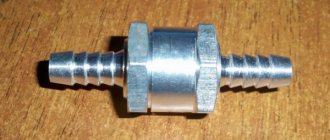
- If the pressure drops to zero, this is a sign of a faulty fuel pressure regulator (FPR). It will be necessary to remove and replace it or install a new check valve for the fuel pump motor.
- Raise the rpm to 3000, watching the pressure gauge needle. If the arrow goes down, there is a problem with the fuel pump.
- If the fuel pump does not provide the required pressure, the strainer is probably clogged, and maybe the fuel filter of the pump is clogged.
- If the above signs are not confirmed, it is necessary to check the TPS, IAC, mass air flow sensor, and engine cylinder compression.
What does the adsorber valve do?
Many problems are related specifically to the adsorber valve. In essence, this is a very simple device that opens or closes under certain conditions (the engine is running or turned off).
If the valve works well, then there are no problems at all; you may not even know about its presence in your system.
However, when a breakdown occurs, for example, the adsorber cavity itself becomes clogged, or the valve does not work. The car may subsequently suffer serious damage. Because the cavity is not purged, and the pressure from the tank is not relieved.
see also
- Ventilation in an outdoor toilet
- Ventilation of the under-roof space in a cold attic
- How to ventilate the floor in a bathhouse
- Sign of a dove in the ventilation
- Height of the pipe for ventilation in the house
- The ventilation in the kitchen is not working, who should I contact?
- Installation of ventilation valves in plastic windows
- The apartment has poor ventilation, what should I do?
- Ventilation in a house made of aerated concrete
- Smoking room ventilation
- Drilling walls for ventilation
Tank ventilation. It smells like gasoline. The reason has been found - logbook of Lada 2108 German 1991 on DRIVE2
About a month ago, when it was sunny outside and over +24 degrees, the smell of gasoline appeared several times while driving. Having crawled around the entire engine compartment, I still couldn’t find any leaks. Then I decided to check if the tank cap was closed (it’s locked with a key). — It turned out to be open, and when I unscrewed it a little, it made a good fuss. — the smell of gasoline stopped. Then, when after a while the aromas began again, I stopped, again relieved the pressure in the tank through the cap, and the smell went away.
After reading on the Internet about tank ventilation, as far as I understand, I should have a two-way valve
but I do not have it. In its place is a rubber plug, under which there is nothing.
As far as I understand, this valve is not present on injection machines, those with an adsorber. But I don’t have it either.
Having removed the bumper from one side, the following picture was revealed to the front door:
1 - this tube is connected to the top of the tank (as I understand it is just ventilation) 2 - it is connected to a gravitational (whatever it is) sensor, and then goes somewhere forward behind the tank. - It turns out that my system is closed. There is no ventilation. Now I ride with the lid not tightly screwed on. When it is opened, nothing happens. But how can I properly do this ventilation? After all, it’s not an option to ride like this all the time. I’m thinking of doing it like on a classic, putting out a ventilation tube next to the neck, and I’m thinking of throwing out the separator altogether... But what kind of tube should I put out? Where to connect the rest?—-
Everything seems simple, BUT: 1. I have a gravity valve (No. 10 on the injection diagram). It is not on the carburetor, and judging by its appearance, it has been there since the factory.2. The hose (No. 20) which in the carburetor circuit goes from the separator to the valve (No. 21) is connected to a metal hose and goes behind the tank (there was no way to track where exactly it goes) I had and still have a carburetor car. There is clearly no collective farm or alterations. Everything is in the same condition and it’s clear that it was like this from the factory. If I start remaking the system according to the carburetor diagram, then where should I put the second hose? Which one is from the gravity sensor?—UPD 2:
I climbed under the car again:
1 - the hose connects to the filler neck 2 - goes to the separator 3 - goes from the separator through the gravity sensor
A flexible hose after the separator and gravity sensor is connected to a metal
He goes around the tank and goes somewhere forward
In the evening I tracked down where this highway goes
It comes out in the engine compartment, where it is plugged with a bolt... Now it’s clear why it stank of gasoline in hot weather: The gasoline expanded, the vapors created pressure, which came out under the hood through this plugged tube. Well, you can breathe a sigh of relief and bring this hose out under rear bumper. —Everything is fine, but from all this I have a question: is it still like it was from the factory? Where did this pipe connect under the hood? The car is an export car - from Germany, it was and is carburetor. Initially there was an automatic choke, but then it was converted to a regular one.
Repair of the vapor removal system from the gas tank - logbook Lada 2110 Drakosha 2001 on DRIVE2
Hi all. It all started with the fact that when I opened the gas cap, it hissed very loudly, louder than ever, so there was no pressure. and this is of no use. Last visit to the guys on the server, from above I saw leaks from the tank. I disassembled the seat and pressed from the fuel module. changed the rubber band + worn out, smells bad. I checked after a while. presses the 2 bolts again hmmm. I planned to take the elevator. but somehow I looked under the car and there was a puddle under the left rear wheel. oh... Benz these are pipes leading to the separator .. but it’s under the left arch, and in theory everyone has it under the right one?! or I'm wrong?
The pipes are all rotten and all clogged. and how I hadn’t noticed before.
The pipes are kind of strange... Antoshka walked around the entire market, then the bakery, there are no such pipes anywhere... Well. then the collective farm
How it was: the system was like this: a gas-tight tube 40 cm from the tank, and in it there is a metal tube running directly under the arch, with a bunch of bends, and from there a 40 cm tube to the separator, and from the separator there is a 40 cm pipe, and such a metal pipe is connected to containers, but there is only one stump, no valve, etc.
How they did it. The tank tube was not changed, it was also metal. but from 99 fuel, cut to the required size and bent as necessary, so a tube for the separator, a tube from the separator 30cm, and a two-way valve.
Now at least it can withstand some pressure :-)))
The photo was taken and didn’t come out because... Tired and tired :-(if I do it later, I’ll post it
The fuel system of a car is designed to store fuel reserves, purify fuel and air from impurities, and supply air and fuel to the engine cylinders. The fuel system consists of a fuel tank, fuel module, fuel filter, fuel rail with injectors, air filter, fuel pipes, air ducts, throttle valve, intake module and gasoline vapor recovery system.
The air entering the engine cylinders is cleaned of dust by an air filter. The air filter is installed in the engine compartment on three rubber supports. The filter element is replaceable and made of special paper. To prevent contaminated air from entering the intake tract, there is a sealing lip at the top of the element. To replace the filter element, the filter cover is removed. Clean air passes through the mass air flow meter (for details, see 8.4) through the air duct to the throttle valve.
The throttle valve regulates the amount of air entering the engine cylinders. The operation of the shock absorber from the gas pedal is a cable. The shock absorber rotates around an axis in the housing (pipe). The throttle body is attached to the intake flange.
Throttle group: 1 - throttle control sector; 2, 4 — fittings for connection to the engine cooling system; 3 — fitting for removing gas from the crankcase; 5 — throttle position sensor; 6 — idle speed regulator; 7 — fitting for connecting to the adsorber; 8 — throttle valve; 9 — throttle body pipe
The housing has a channel for coolant. The channel is connected to the cooling system by rubber hoses. Circulating coolant through the throttle body prevents the body's internal air spaces from freezing in the winter. The housing contains fittings for connection to the adsorber and the crankcase ventilation system.
The throttle body with the throttle position sensor and idle speed control mounted on it (for details, see 8.4) forms the throttle assembly.
The fuel supply is stored in a tank with a capacity of 43 liters. The fuel tank is steel, welded from two stamped parts. The tank is suspended from the bottom of the vehicle on two steel clamps. The filler neck of the fuel tank is located on the right side of the car and is closed with a lid. Fuel is supplied from the tank by a submersible electric pump.
The pump is installed in the fuel tank. To access the pump, a hatch with a cover is made in the bottom of the car under the rear seat cushions.
A strainer is installed at the inlet of the fuel pump, which traps small solid particles of debris that enter the fuel tank along with gasoline. The pump is driven by an ECU command (see 8.4) when the ignition is turned on. If no attempt is made to start the engine, after 2-3 seconds the ECU will turn off the fuel pump.
Fuel pump: 1 - protrusion for attaching the filter; 2 — fuel intake hose for connecting the filter; 3 - body; 4 — electrical connector block; 5-outlet pipe (complete) for connection to the fuel module cover with a corrugated tube
On a car with an MP7.0 model ECU, when the engine is first started after connecting the battery, the fuel pump can only be turned on simultaneously with the starter; in the future, the fuel pump will work as switched on in cars with other types of ECU. However, after three consecutive starts without starting the engine, the fuel pump will only be activated simultaneously with the starter.
From the pump, through the corrugated hose of the fuel module (see below), gasoline enters the fuel line and then into the fuel filter, where the fuel is more thoroughly cleaned.
The fuel filter is a paper filter installed in a non-separable metal housing.
Clean fuel enters the fuel rail through the fuel line.
Fuel filter for engine 21124 (1.6i): 1 - inlet pipe; 2 - body; 3 — fuel flow direction arrow (marked on the filter housing); 4 - outlet pipe
The fuel filter for the 2112 (1.5i) engine has threaded fittings.
The fuel rail holds the four injectors and supplies them with fuel. The connection of the rack to the nozzles is sealed with rubber rings. The ramp is attached to the header with bolts.
The fuel pressure regulator is a bypass valve that maintains an operating pressure in the system (fuel line) of 284-325 kPa for the 2112 engine or 378-390 kPa for the 21124 engine, which is required for proper operation of the injection system (see 8.4 for more details).
In accordance with EURO II environmental requirements, the car is equipped with a fuel vapor recovery system; the super-fuel space of the tank is connected to the atmosphere not directly, but through the elements of this system.
Separator location on a vehicle with engine 21124 (1.6i):
1 - separator; 2 — bracket for fastening the separator; 3 - gravity valve
On a car with a 2112 engine, a safety valve is also installed here. On a vehicle with a 21124 engine, the safety valve is located in the fuel tank cap.
Adsorber: 1 — adsorber body; 2 pipes for connecting the internal cavity of the adsorber with the atmosphere; 3 — adsorber purge valve; 4 — valve connecting pipe; 5 - adsorber connection pipe
The system consists of a separator, canister gravity valve, canister purge valve, check valve, connecting pipes and hoses. The separator and gravity valve are mounted under the left rear fender of the vehicle. In the separator, gasoline vapors are partially condensed and returned to the fuel tank. The gravity valve prevents fuel from leaking from the tank when the vehicle rolls over.
From the separator, non-condensed gasoline vapors pass through pipes and connecting pipes into the adsorber, which prevents vapors from entering the atmosphere. An adsorber is a container in which gasoline vapors are absorbed by activated carbon. When the engine is running at high engine speed, the ECU sends a signal to open the canister purge valve, and gasoline vapors are drawn into the intake module receiver.
Characteristics of the fuel system of the 2112 (1.5i) engine
Diagram of the fuel system of the engine 2112 (1.5i): 1 - injectors; 2 - fuel rail; 3 — diagnostic fitting of the fuel rail (to check the fuel pressure, closed with a screw cap); 4 - adsorber; 5 - check valve; 6 — throttle valve; 7 - gravity valve; 8 - safety valve; 9 - separator; 10 - filling tube; 11 — fuel filter; 12 — fuel supply line; 13 - fuel line connecting the output of the fuel module to the fuel filter; 14 — fuel module; 15 — fuel tank; 16 — fuel drain hose; 17 - fuel pressure regulator
Location of elements of the engine fuel system [Engine with decorative trim removed.] 2112 (1.5i) in the engine compartment: 1 - receiver; 2 — throttle valve; 3 — tube for supplying air to the throttle valve; 4 — air filter; 5 — fuel pressure regulator; 6 — throttle control cable; 7 — fuel rail; 8 — diagnostic device; 9 — adsorber check valve; 10 - adsorber
Air is supplied to the intake valves of the cylinders of the 2112 (1.5i) engine through the receiver and the intake manifold. These elements of the intake tract are connected to each other by rubber connections.
The fuel pump is combined with the fuel level sensor into one unit - the fuel module (often called the electric fuel pump). The pump pressurizes fuel from the tank through the fuel filter into the fuel line.
The fuel pressure regulator is installed on the fuel rail. Excess fuel is returned to the tank via the return line.
Fuel module of engine 2112 (1.5i): 1 - fuel level sensor; 2 - connecting block; 3 — inlet pipe; 4 — outlet pipe (discharge); cover 5 modules; 6 — module cover guide; 7 — electric fuel pump in a plastic casing; 8 - suction chamber
Fuel rail for engine 2112 (1.5i) complete with injectors: 1-
hose for supplying fuel to the fuel rail; 2 — fuel line hose for draining fuel into the tank; 3, 4, 5 and 6 - nozzles; 7 — diagnostic fitting (for checking fuel pressure, closed with a screw plug); 8 — fuel rail; 9 — fuel pressure regulator;
Characteristics of the fuel system of engine 21124 (1.6i)
Location of engine fuel system elements [Engine with plastic cover removed.] 21124 (1.6i) in the engine compartment: 1 - intake module; 2 — throttle valve; 3 — tube for supplying air to the throttle valve; 4 — air intake; 5 — air filter; 6 — fuel rail; 7 — throttle control cable; 8 — fuel rail fitting; 9 — adsorber check valve; 10 - adsorber
Engine intake module 21124 (1.6i): 1 - flange with an o-ring for attaching the throttle valve; 2- receiver; 3- Intake manifold flange with O-ring for connection to the head
Fuel system diagram for engine 21124 (1.6i): 1 - injectors; 2 - fuel rail; 3 — diagnostic fitting of the fuel rail (to check the fuel pressure, closed with a screw cap); 4 - adsorber; 5 - check valve; 6 — throttle valve; 7 - gravity valve; 8 - separator; 9 — fuel line hose connecting the fuel filter to the tee; 10 — fuel line hose connecting the fuel filter to the outlet of the fuel module; 11 — fuel module; 12 — fuel filter; 13 - filling tube; 14 — fuel tank; 15 — hose connecting the fuel filter and the fuel module with the fuel line; 16, 18 — metal fuel pipes; 17 — connecting pipe; 19 - fitting for connecting the fuel rail to the fuel line
Air is supplied to the intake valves of the engine cylinders through the intake module.
The engine intake module 21124 is made of special plastic and is a one-piece element.
Engine fuel module 21124 (1.6i): 1 - inlet pipe (for supplying fuel to the pressure regulator); 2 outlet pipes (discharge); cover 3 modules; 4- fuel level indicator sensor; 5- suction chamber; 6 — module cover guide
There are two valves on the filler cap: one for emergency release of fuel vapor pressure from the tank (which is possible when the ambient temperature rises), and the other for drawing air from the atmosphere when the fuel is consumed by the tank. (this eliminates the occurrence of a strong vacuum in the tank).
The fuel pump is combined with the fuel level sensor and fuel pressure regulator into one unit - the fuel module (often called the electric fuel pump).
Engine fuel pressure regulator 21124 (1.6i): 1- hole for draining excess fuel; 2, 4 — sealing rings; 3 holes for fuel supply to the regulator; 5- body; 6 - terminal for connecting the regulator to ground
On a vehicle with a 21124 (1.6i) engine, fuel from the pump (through the outlet pipe of the fuel module) enters the fuel filter. Clean gasoline is returned through the fuel line and through the tee to the inlet pipe of the fuel module, and then supplied to the fuel rail. Excess fuel is drained through the pressure regulator into the tank. The fuel pressure regulator is installed in the fuel module cover.
Fuel hose for engine 21124 (1.6i) assembled with injectors: 1 - fitting for connecting to the fuel line; 2- fuel rail; 3 - diagnostic fitting (for checking the working pressure, closed with a screw plug); 4, 5, 6 and 7 - injectors
Lada VAZ-2110 (2111, 2112). Fuel system for VAZ-2111, -2112 engines
Fuel supply diagram for an engine with a fuel injection system: 1 - injectors; 2 — fuel pressure regulator fitting cover; 3 — injector ramp; 4 — bracket for fastening fuel pipes; 5 — fuel pressure regulator; 6 — adsorber with solenoid valve; 7 — pipe for suction of gasoline vapors from the adsorber; 8 — throttle valve; 9 - two-way valve; 10 - gravity valve; 11 - safety valve; 12 - separator; 13 — separator tube; 14 — fuel tank cover; 15 - filling tube; 16 — filling hose; 17 — fuel filter; 18 — fuel tank; 19 — electric fuel pump; 20 — fuel drain hose; 21 - fuel supply line.
Fuel is supplied from a tank located under the floor in the rear seat area. The fuel tank is made of steel and consists of two molded halves welded together. The filler neck is connected to the tank with a gas-resistant rubber hose secured with clamps. The plug is sealed.
The fuel pump is electric, submersible, rotary, two-stage, installed in the fuel tank. The developed pressure is at least 3 bar (3 atm). The fuel pump is activated by a command from the injection system controller (with the ignition on) via a relay. There is a hatch in the bottom of the car for access to the pump under the rear seat. From the pump, fuel under pressure is supplied through a hose to the fine filter, and then through steel fuel hoses and rubber hoses to the fuel rail.
The fine fuel filter is non-removable, in a steel housing, with a paper filter element. There is an arrow on the filter housing that must coincide with the direction of fuel movement.
The fuel rail is used to supply fuel to the injectors and is connected to the intake manifold. On the one hand, it has a fitting for monitoring fuel pressure, on the other, a pressure regulator. The latter changes the pressure in the fuel rail - from 2.8 to 3.2 bar (2.8-3.2 atm) - depending on the vacuum in the receiver, maintaining a constant difference between them. This is necessary for accurate dosing of fuel by injectors.
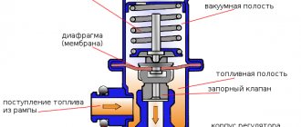
The fuel pressure regulator is a fuel valve connected to a spring-loaded diaphragm. The valve is closed by a spring. The diaphragm divides the regulator cavity into two isolated chambers: “fuel” and “air”. The “air” is connected to the receiver by a vacuum hose, and the “fuel” is connected directly to the rail cavity. When the engine is running, the vacuum, overcoming the resistance of the spring, tends to retract the diaphragm, opening the valve. On the other hand, the fuel presses on the membrane, also compressing the spring. As a result, the valve opens and some of the fuel enters the tank through the exhaust pipe. When you press the accelerator pedal, the vacuum behind the throttle valve decreases, the diaphragm is lower
closes the valve under the action of a spring - fuel pressure increases. If the throttle valve is closed, the vacuum behind it is maximum, the diaphragm pulls the valve harder - the fuel pressure drops. The pressure drop is determined by the spring force and the size of the valve opening and cannot be adjusted. The pressure regulator cannot be separated; if it fails, it must be replaced.
The injectors are attached to the rail using a rubber O-ring. The injector is an electromagnetic valve that allows fuel to pass through when voltage is applied to it and is blocked by the action of the return spring in the de-energized state. At the outlet of the injector there is a nozzle through which fuel is injected into the intake manifold. The injectors are controlled by the injection system controller. If there is a break or short circuit in the injector winding, it should be replaced. If the injectors are clogged, they can be washed without disassembling them at a special stand at a service station.
The closed loop injection system uses a vapor recovery system. It consists of an adsorber installed in the engine compartment -
section, separator, valves and connecting pipes. Fuel vapor from the tank is partially condensed in the separator, and the condensate is discharged back into the tank. The remaining vapors pass through gravity and two-way valves. The gravity valve prevents fuel from leaking from the tank when the vehicle rolls over, and the two-way valve prevents the pressure in the fuel tank from becoming too high or low.
Then the fuel vapor enters the adsorber, where it is absorbed by activated carbon. The second adsorber nozzle is connected by a hose to the accelerator assembly, and the third is connected to the atmosphere. However, when the engine is turned off, the third fitting is closed by an electromagnetic valve, so that in this case the adsorber does not communicate with the atmosphere. When the engine starts, the injection system controller begins to send control pulses to the valve with a frequency of 16 Hz. The valve communicates the absorber cavity with the atmosphere, and the absorbent is purged: gasoline vapors are drawn through the tube into the recipient. The higher the engine air consumption, the longer the control pulses and the more intense the pumping.
In an open loop injection system, the vapor recovery system consists of a separator with a two-way check valve.
The air filter is installed in the left front part of the engine compartment on three rubber mountings (supports). The filter element is made of paper; after installation, its waviness should be parallel to the axis of the car. After the filter, the air passes through the mass air flow sensor and enters the intake pipe leading to the throttle valve. A throttle assembly is attached to the receiver. By pressing the accelerator pedal, the driver opens the throttle, changing the amount of air entering the engine and therefore the fuel mixture - after all, the fuel delivery is calculated by the controller based on air flow. When the engine is idling and the throttle valve is closed, air flows through the idle air control valve, a valve controlled by the controller. The latter, by changing the amount of supplied air, maintains a given minimum speed (in a computer program). The idle air control cannot be separated; if it fails, it must be replaced.
Signs of a malfunctioning canister valve
As it becomes clear, problems arise with the power system:
It is also worth noting that the reason is not always in the valve; often the can of activated carbon itself (that is, the adsorber cavity itself) can become clogged. If necessary, it must be replaced or disassembled and cleaned - dried, that is, the filtration of gases must be restored so that they pass unhindered.
Now a useful video.
If you experience these malfunctions, then you definitely need to look - check the valve and, if necessary, change it, fortunately it costs a penny. And also the cavity itself with activated carbon.
Signs of malfunction of the VAZ-2110 power system
Considering the number of power system components, it is quite difficult to unambiguously determine the cause of the malfunction. But, if you know the main “symptoms” of a breakdown, then the process of finding the cause will speed up many times. So, we list the main signs of failure of power system components:
- The car stalls (does not start). Check the operation of the fuel pump by listening to the sound from under the rear seat (with the ignition on).
- The revolutions “float”. This may be due to a malfunction of the idle air control or fuel pressure regulator in the rail.
- The engine "troits". As a rule, the cause is faulty injectors.
The fuel system of the VAZ 2110 16-valve injector has exactly the same features as the 8-valve injector.
Adsorber operation
I will try to briefly and clearly explain the principle of operation of the adsorber and purge valve. This unit is poorly described on the Internet and very often there are erroneous opinions on the principle of its operation.
The adsorber is primarily designed to reduce environmental pollution from gasoline vapors. Everyone knows that gasoline evaporates very well. So, on cars without an adsorber, gasoline evaporates into the atmosphere, and on cars with an adsorber, these vapors are burned in the engine cylinders.
The principle of operation of the adsorber on different cars is the same, the only difference is in the shape and location of the adsorber and the purge valve. For some, it is installed in the engine compartment, and, for example, for the Lacetti, it is installed under the bottom near the rear wheel, and the purge valve is in the engine compartment.
Fuel vapor from the tank enters the adsorber (a container with activated carbon) through a fitting marked “TANK”, where it accumulates while the engine is not running. The second canister fitting with the inscription “PURGE” is connected by a tube to the canister purge valve, and the third with the inscription “AIR” is connected to the atmosphere.
1 - AIR vent fitting, 2 - TANK fitting for the tube for supplying fuel vapors from the tank to the canister, 3 - PURGE fitting for the tube for removing fuel vapors from the adsorber to the valve
When the engine is stopped, the purge solenoid valve is closed, and in this case the adsorber does not communicate with the intake manifold.
When the engine is running, the electronic unit, controlling the solenoid valve, purges the adsorber with fresh air due to the vacuum in the intake manifold. That is, the vapors are sucked out of the adsorber.
Gasoline vapors are mixed with air and discharged into the intake manifold behind the throttle and then enter the engine cylinders.
Principle of operation
Gasoline vapors generated in the tank rise upward and first enter the separator through an opening at the neck of the tank. There they condense and drain back into the tank. That part of them that does not have time to turn into condensate, through the gravity valve through the steam line, goes directly into the absorber, where it is absorbed by activated carbon. This happens when the engine is not running.
Otherwise, while the car is moving, with the engine warm, the control system opens the solenoid valve and the absorber is purged. Gasoline vapor, together with air entering through another valve, is blown into the engine intake pipe, where it is burned.
It turns out to be a kind of double effect.
- firstly, the atmosphere is not polluted by unnecessary, harmful fumes;
- secondly, we have, albeit small, fuel savings. After all, if there were no absorber, the fuel would simply evaporate.
In a word, everything was described as an ecologist, everyone is fine, everyone is happy.
VAZ 2110 | Evaporative Evaporative Recovery System (EVAP)
Evaporative Evaporative Recovery System (EVAP)
The EVAP system adsorbs fuel vapors and burns them as part of the combustible mixture during normal engine operation.
Any fuel vapor recovery system must include an adsorber filled with activated carbon, into which gasoline vapors are collected. The difference between one system and another may lie in the control of evaporation removal. Below is a description of a system typical for the models of the car brand described in this Manual, which should provide the owner with information sufficient to understand the principle of fuel vapor removal on his car.
The description below does not purport to uniquely correspond to the description of the system used on a particular vehicle, but gives an idea of the typical circuit adopted for the removal of fuel vapors on models equipped with a fuel injection system. While all of the components listed below are required in any EVAP system, there may be additional devices included that are unique to your vehicle. Refer to the VECI label and the vacuum hose routing diagram located under the vehicle's hood.
The fuel filler cap is equipped with a two-way safety valve. The valve is used to release vapors accumulated in the fuel tank into the atmosphere in the event of a failure of the EVAP system.
Another shut-off (unloading) valve is installed on the fuel tank and serves to regulate the removal of fuel vapor from the tank into the carbon adsorber, depending on the presence of excess or negative pressure in the tank (depending on the ambient temperature).
VAZ 2110 - modifications
VAZ-21100. The base model which was produced from 1996 to 2000. The car was equipped with an 8-valve carburetor VAZ-21083 engine with a displacement of 1.5 liters and a power of 69 horsepower.
VAZ-21101. This modification has been produced since 2004, equipped with an 8-valve gasoline injection engine with a displacement of 1.6 liters.
VAZ-21102. Like the previous modification with an 8-valve injection engine, but with a volume of 1.5 liters.
VAZ-21103. Modification of the “tens” with a 16-valve injection engine with a working volume of 1.5 liters.
VAZ-21103M. A restyled modification of the VAZ-21103, equipped with a 16-valve petrol injection engine with a displacement of 1.5 liters and a power of 92 horsepower. Produced since 2002.
VAZ-21104. The modification is equipped with a 16-valve petrol injection engine with a working volume of 1.6 liters.
VAZ-21104M. A restyled modification of the VAZ-21104, equipped with a 16-valve petrol injection engine with a displacement of 1.6 liters. Produced since 2004.
VAZ-21106 GTI. The engine of the VAZ-21106 GTI is the most powerful and expensive modification that has been produced since 2000. The car was equipped with a 2-liter 16-valve Opel C20XE gasoline engine with a capacity of 150 horsepower. The car was fitted with a body kit with swollen arches, and the track was widened by 76 millimeters. It was equipped with R15 wheels with low-profile tires.
VAZ-21106 Coupe. Coupe VAZ-21106 in a coupe body. A distinctive feature of the car was the presence of only two doors, which were lengthened by 250 millimeters, while the body was shortened by 170 millimeters. The engine was installed the same as in the previous VAZ-21106 GTI model.
VAZ 21106 WTCC. A sports modification of the 106 model, it participated in the 2008 FIA WTCC international championship.
VAZ 21107. Modification of the car for rally competitions. It was equipped with a welded safety cage and a different suspension design.
VAZ 21108 "Premier". A modification with a body lengthened by 170 millimeters in the rear door area, which provided more convenient entry and exit of passengers. It was equipped with a 1.5-liter injection 16-valve engine.
VAZ 21109 “Consul”. 4-seater luxury limousine based on the VAZ-2110 car. In addition to the length of the body, the dimensions of the rear door were also increased, for more convenient entry and exit of passengers. Equipped with a 1.5 liter engine and R14 or R15 wheels. Overall dimensions: length - 4950 mm, width - 1700 mm, height - 1440 mm. Fuel consumption in the urban cycle is 9.5 liters per 100 kilometers.
VAZ 2110-91. Modification of the VAZ-2110 with a 1308 cm3 rotary piston engine. The car could reach speeds of up to 240 km/h, and acceleration from 0 to 100 km/h took 6 seconds.
A car with a 16-valve injection engine in the Gran Lux configuration includes:
- Electric windows;
- Door locking;
- Trunk lock lock;
- Velvet seat upholstery;
- Immobilizer;
- Heated front seats;
- Ventilated 14-inch brake discs;
- Rear spoiler with additional brake light;
- Fog lights.
Operating principle of the adsorber
Many people mistakenly believe that when the engine starts, voltage is immediately applied to the canister valve and it opens, purging the canister. I even saw “manuals” and “training videos” about this. In fact, the purge valve is controlled by the ECU using special algorithms based on readings from temperature, air flow, etc. sensors.
The greater the engine air consumption, the longer the duration of the ECU control pulses and the more intense the purging.
It is impulses, and not just the supply of voltage! Therefore, there is such a thing as “adsorber purge duty cycle,” which ranges from 0% to 100%.
Here is the duty cycle of the canister purge in the Chevrolet Explorer diagnostic program. During the entire trip, this is only the first signal from the ECU to purge, equal to only 6%. So this is a complex and important process in the operation of the engine.
Possible malfunctions in the operation of the device
The VAZ 2114 absorber, due to its intended purpose, is susceptible to clogging and at some point may become faulty. Problems are not easily determined and often only by secondary symptoms, for example, increased pressure in the fuel tank. It’s just that gasoline vapors, due to wear of the separator, remain locked in the space of the tank and begin to put pressure on its walls. An increase in pressure can be detected when unscrewing the tank cap - a characteristic hissing sound is heard.
Sometimes the gas tank cap simply shoots out of the neck, which means that the pressure has reached a critical level and the adsorber must be urgently changed. If there is a problem with the adsorber, the engine speed begins to jump up and down. Many car owners write on forums that you can remove the VAZ absorber and not suffer. But everything is not so simple, and there are never unnecessary parts in cars.
As for malfunctions, the problem area of this adsorbent system is the purge valve. You can repair it yourself
All you need is a flathead screwdriver, but be careful when removing it. The point is in the valve fastening, it is often not metal, but plastic, it is not difficult to break it
The mount is located on the engine cover. There are also clamps on the valve itself, which also require a careful approach. We remove them and take out the problematic part.
If you blow into the valve and air comes out of it, this means a 100% malfunction. A normal part will not allow air to pass through. If there is a problem with the valve, the car experiences problems when starting the engine hot, and gasoline consumption increases. If the problem is not corrected, there will be a Check Engine and loss of normal driving dynamics. Failure of the adsorber seal and failure of the purge valve can cause unstable engine operation at idle until it stops.
So, let's move on to valve repair. In its upper part there is an adjusting screw fixed with epoxy resin. Screw the screw in until it stops, counting the turns so that if something happens, you can return the canister valve to its original position. You can drop a little carburetor flushing fluid into the valve fittings. Then we blow it in the open position with compressed air. The repairs are done. The reason that the adsorber valve becomes clogged is low-quality gasoline, as well as particles of the filler of the adsorber itself. Therefore, it is not necessary to immediately change the faulty part. In addition to the signs already indicated, a malfunction of the adsorbing parts of the fuel system can be detected by the smell of gasoline in the cabin. Usually this means either a break in one of the pipes of the VAZ absorber system, or a failure of the already described purge valve.
The valve can also wear out due to heat near the radiator, and there is nothing you can do to help it. The quality of the material from which the adsorber valve is made is not the best. The only solution can be to replace or change the location to a cooler one, for example, closer to the adsorber itself.
Canister valve. How to check it
The principle of checking on most cars is the same, but we will look at the example of the Chevrolet Lacetti.
Problems with the canister purge valve can be divided into several main points:
It is very easy to check the pulses, wiring and valve winding with the Chevrolet Explorer program, in the “mechanism control - canister purge valve test” tab. When you click on the “ON” button in the program diagram, we will see the following signals
This means that the ECU is giving a command to the valve. At the same time, the sound of clicks will emanate from the valve in time with these signals, which, in turn, means that the pulses reach the valve and the winding is intact, since the valve is activated.
By the way, if you don’t have a diagnostic adapter yet, then I advise you to definitely read the diagnostics section and purchase an adapter.
The electrical part is OK. We checked this. But to be sure that the valve is not physically jammed, it can be removed and checked. It is very easy to dismantle and it takes me no more than 30 seconds.
Solenoid valve malfunctions
If the adsorber is in uninterrupted mode almost all the time, the purge valve can easily stop functioning. This will damage the fuel pump. If the adsorber does not ventilate properly, gasoline will gradually accumulate in the intake manifold.
This leads to some rather unpleasant “symptoms”:
- At idle, so-called dips appear.
- Traction is impaired (it seems that the vehicle is constantly losing power).
- When the engine is running, the sounds of the valve operating are not heard.
- Fuel consumption increases noticeably.
- When opening the gas tank cap, a hissing and whistling sound is heard.
- The fuel tank sensor literally lives its own life (it can show that the gas tank is full, and a second later - that there is nothing in it).
- An unpleasant gasoline “aroma” appears in the car interior.
Sometimes the filter element, on the contrary, makes too loud sounds, which are also not the norm. To make sure that the cause is a faulty valve and not a timing belt, just press the gas sharply. If the sound effect remains the same, then most likely the problem is in the canister valve.
In this case, it is recommended to slightly tighten the adjusting screw of the device. However, you need to tighten it no more than half a turn. Holding too tightly will result in a controller error. If such manipulations do not help, then you need to conduct a more detailed diagnosis.