Many car enthusiasts would like to replace the standard incandescent light bulbs in their cars with LEDs . The advantage of the latter is undoubtedly - low current consumption, durability, higher light output, no heating. It's nice to leave the headlights on and discover in the morning that the battery had no intention of being discharged. This article will help you replace car light bulbs with LEDs yourself and avoid common mistakes.
The main points that we need to learn:
1. Voltage in the vehicle’s on-board network . Typically this is 12 - 13 V when the engine is off and 13 - 14.5 V when the engine is running.
2. The supply voltage of a typical LED is 3.5 V. Depending on the color, this can be: for yellow and red LEDs - 2 - 2.5 V; for blue, green, white - 3-3.8 in. The typical current of a low-power LED is 20 mA, and a high-power LED is 350 mA. 3. Not all LEDs , unlike light bulbs , illuminate the space around them. This must be taken into account when replacing indicator lamps , for example, in the dashboard . When purchasing, you should pay attention to the type of lens or, if possible, ask the seller. Narrow-beam LEDs have a small lens at the end. In general, try to check this when purchasing, or even better, buy and try several different ones. 4. An LED , like a battery , has a plus and a minus . The minus is called the cathode, the plus is the anode; in the diagrams they are depicted like this:
It should be clear to you that you can just pick it up and turn it on
LED into the car's on-board network - this means it is guaranteed to burn out.
Calculation of a resistor for an LED
To compensate for the resistance of the LED, you must first select a resistor with a higher resistance. Such a calculation will not be difficult for those who know what Ohm’s law is.
Mathematical calculation
Based on Ohm's law, we calculate using the following formula:
where Un is the network voltage; Uvd is the voltage for which the LED is designed; Ivd – current.
Let's say we have an LED with the following characteristics:
2.1 -3.4 volts – operating voltage (Uvd). Let's take an average value of 2.8 volts.
20 amperes - operating current (Ivd)
220 volts – mains voltage (Un)
In this case, we obtain the resistance value R = 10.86. However, these calculations are not enough. The resistor may overheat. To prevent overheating, you need to take into account when choosing its power, which is calculated using the following formula:
Please note that the resistor is connected to the positive terminal of the diode. Determining the polarity of the diode is quite simple: the positive contact in the bulb is larger in size than the negative one. For clarity, we recommend watching the video:
For clarity, we recommend watching the video:
Graphic calculation
The graphical method is less popular for calculating a resistor for an LED, but can be even more convenient. Knowing the voltage and current of the diode (they are also called current-voltage characteristics - I-V characteristics), you can find out the resistance of the desired resistor from the graph presented below:
Here is a calculation for a diode with a rated current of 20 mA and a power supply voltage of 5 volts. Drawing a dotted line from 20 mA to the intersection with the “led curve” (blue color), we draw an intersecting line from the Uled straight line to the straight line and get a maximum current value of about 50 mA. Next, we calculate the resistance using the formula:
We get a value of 100 Ohms for the resistor. We find the dissipation power for it (we take the current strength from Imax):
Theory
To ensure that the LEDs do not burn out, it is important to correctly calculate the limiting resistor.
Mathematical calculation
You can do the necessary calculations yourself; for low values, you do not need a calculator. Or using a special program that does the calculations for you. When calculating the resistance of a quenching resistor, you need to know Ohm's law. R = U-ULED /ILED U - mains voltage;
ULED is the value of the voltage that is optimal for the operation of the diode. I LED is the current for which the element is designed to operate. To prevent overheating of the resistor during operation, it is necessary to additionally calculate the optimal power for this voltage. P = (U-ULED)*ILED
In this circuit, a resistor is connected to the cathode of the luminous element.
Connecting super-bright and powerful LEDs to 12V
First, let's look at how to connect one powerful, super-bright LED to 12 Volts. Let's say we have at our disposal a device whose operating current is 350 mA. At the same time, the voltage drop across it in operating mode is approximately 3.4 Volts. It is easy to calculate that the power consumption of such a device is 1 W.
It is clear that you cannot connect it directly to 12 Volts. We will have to somehow “extinguish” some of the tension. In the simplest cases, quenching (current-limiting) resistors are used for these purposes. It is connected to the LED in series. The power supply circuit for one LED is shown in the photo.
To calculate the value of the current-limiting resistor, use the formula:
Armed with a calculator, it is easy to calculate that the resistance will be about 25 ohms. It will dissipate power, which is calculated using the formula:
In our example, the power will be about 3 watts. It is quite difficult to find a resistance of such power, so two 100 Ohm resistors with a power of 2 W, connected in parallel, can be used as a quenching resistor.
In principle, based on these calculations, it is already possible to create a practical design. By connecting the LED to 12V via a switch, you can organize additional lighting for the car’s engine compartment, trunk or glove box.
We have shown that the creation of such a scheme is possible, but its application is irrational. It is easy to see that two-thirds of the power consumed by the structure comes from the quenching resistor and is therefore wasted. Below we will tell you how to avoid unnecessary losses.
How to connect to 12 volt car
Connecting LEDs to the vehicle's on-board network does not differ significantly from connecting to other power sources. Just don’t forget that a car’s battery in normal condition produces not 12 Volts, but approximately 14 Volts.
Even when connecting, you must remember that not every car has an on-board voltage stabilization system that works reliably. Therefore, when calculating quenching resistors, it is better to take the supply voltage equal to 15 - 17 volts. This will somewhat reduce the brightness of the glow, but will significantly extend the service life, since the LED will operate in a “gentle” mode.
Calculation of LED resistor (using formulas)
When calculating, two quantities are calculated:
- Resistance (value) of the resistor;
- power dissipated by it P.
The voltage sources powering the LEDs have different output voltages. In order to select a resistor for an LED, you need to know the source voltage (Uist), the operating voltage drop across the diode and its rated current. The formula for calculation is as follows:
R = (Uist - Un) / In
When we subtract the nominal voltage drop across the LED from the source voltage, we get the voltage drop across the resistor. Dividing the resulting value by the current, according to Ohm's law, we obtain the value of the current-limiting resistor. We substitute the voltage expressed in volts, the current in amperes and get the nominal value expressed in ohms.
The electrical power dissipated by the damping resistance is calculated using the following formula:
P = (In)2 ⋅ R
Based on the obtained value, the power of the ballast resistor is selected. For reliable operation of the device, it must be higher than the calculated value. Let's look at an example of a calculation.
Example of calculating a resistor for a 12 V LED
Let's calculate the resistance for an LED powered by a 12V DC voltage source.
Let's say we have at our disposal a popular super-bright SMD 2835 (2.8mm x 3.5mm) with an operating current of 150mA and a voltage drop of 3.2V. SMD 2835 has an electrical power of 0.5 watts. Let's substitute the original values into the formula.
R = (12 - 3.2) / 0.15 ≈ 60
We find that a quenching resistor with a resistance of 60 Ohms is suitable. The closest value from the standard E24 series is 62 ohms. Thus, for the LED we have chosen, we can use a ballast with a resistance of 62 Ohms.
Now let's calculate the power dissipation across the resistance.
P = (0.15)2 ⋅ 62 ≈ 1.4
Almost one and a half watts of electrical power will be dissipated at the resistance we have chosen. This means that for our purposes we can use a resistor with a maximum permissible power dissipation of 2W.
All that remains is to buy a resistor with a suitable value. If you have old boards from which parts can be desoldered, then you can select a resistor based on the color marking. Use the form below.
On a note! In the example above, the current limiting resistor dissipates almost three times as much energy as the LED. This means that taking into account the luminous efficiency of the LED, the efficiency of our design is less than 25%.
To reduce energy losses, it is better to use a source with a lower voltage. For example, you can use an AC/AC 12/5 volt DC/DC converter for power supply. Even taking into account the efficiency of the converter, the losses will be significantly less.
Results
In conclusion, the following considerations need to be taken into account when connecting ultra-bright LEDs:
- the most important parameter of an LED is its operating current;
- energy is uselessly dissipated on quenching resistors;
- by using a serial connection, you can reduce losses while simultaneously reducing the number and power of resistors used;
- in the car’s on-board network there is not 12 volts, but somewhat more, and for reliable operation of the connected light-emitting diodes, this factor must be taken into account.
Having remembered all the above connection aspects, you can easily power any LED, in any quantity, from any 12 Volt DC power source.
Parallel connection
Quite often it is necessary to connect several diodes to one source. Theoretically, to power several parallel-connected LEDs, one current-limiting resistor can be used. In this case, the formulas will look like this:
R = (Uist - Un) / (n ⋅ In)
P = (n ⋅ Iн)2 ⋅ R
Where n is the number of parallel-connected LEDs.
Why can't you use one resistor for several parallel diodes?
Even in “Chinese” products, manufacturers install a separate current-limiting resistor for each LED. The fact is that in the case of a common ballast for several LEDs, the probability of failure of light-emitting diodes increases many times over.
If one of the semiconductors breaks, its current will be redistributed through the remaining LEDs. The power dissipated on them will increase and they will begin to heat up intensely. Due to overheating, the next diode will fail and the process will then take on an avalanche-like character.
Example of correct resistor connection
Online calculator
The online calculator for LEDs presented below is a convenient addition that will perform all the calculations independently. With its help, you don’t have to draw or calculate anything manually. All you need is to enter the two main parameters of the LED, indicate their number and the voltage of the power source. With one click of the mouse, the program will independently calculate the resistance of the resistor, select its value from the standard range and indicate the color marking. In addition, the program will offer a ready-made switching circuit.
LEDs today have found application in almost all areas of human activity. But, despite this, for most ordinary consumers it is completely unclear why and what laws apply when operating LEDs. If such a person wants to arrange lighting using such devices, then many questions and searching for solutions to problems cannot be avoided. And the main question will be: “What kind of thing are these resistors, and why do LEDs need them?”
A resistor is one of the components of the electrical network
, characterized by its passivity and, at best, characterized by resistance to electric current. That is, Ohm’s law must be valid for such a device at any time.
The main purpose of the devices is the ability to vigorously resist electric current. Thanks to this quality, resistors are widely used
if necessary, artificial lighting devices, including the use of LEDs.
Why is it necessary to use resistors in the case of LED lighting devices?
Most consumers know that an ordinary incandescent light bulb produces light when directly connected to any power source. The light bulb can work for a long time and burns out only when the filament heats up excessively due to the supply of too high voltage. In this case, the light bulb, in some way, implements the function of a resistor, because the passage of electric current through it is difficult, but the higher the applied voltage, the easier it is for the current to overcome the resistance of the light bulb. Of course, it is impossible to put such a complex semiconductor part as an LED and an ordinary incandescent light bulb on the same level.
It is important to know that an LED is an electrical device.
, for the operation of which it is not the current strength itself that is preferable, but the voltage available in the network. For example, if a voltage of 1.8 V is selected for such a device, and 2 V comes to it, then most likely it will burn out - if the voltage is not reduced in time to the level required by the device. It is precisely for this purpose that a resistor is required, through which the power source used is stabilized so that the voltage supplied by it does not damage the device.
In this regard, it is extremely important:
- decide what type of resistor is required;
- determine the need to use an individual resistor for a specific device, which requires calculation;
- take into account the type of connection of light sources;
- planned number of LEDs in the lighting system.
Is it possible to do without resistors?
Indeed, in some cases it is possible not to use a current-limiting resistor. The LED we reviewed can be directly powered by two 1.5V batteries. Since its operating voltage is 3.2V, the current flowing through it will be less than the rated one and it will not require ballast. Of course, with such power supply, the LED will not produce the full luminous flux.
Sometimes in alternating current circuits capacitors are used instead of resistors as current-limiting elements (more about capacitor calculation). An example is backlit switches in which the capacitors are “watt-free” resistances.
Video “Features of connecting diode lamps in cars”
What needs to be taken into account and what mistakes should not be made - recommendations from a specialist in connecting diode lighting sources are given in the video below (author - Amateur Radio channel).
12 V power supplies are widely used due to their versatility and practicality. This voltage is both safe for humans and sufficient for the operation of many electrical appliances. LEDs were no exception. Today, the range of LEDs has expanded so much that connecting them to 12 volts is not entirely easy. Even 12-volt LEDs with a similar voltage drop require knowledge of certain nuances. In this article we will try to understand in as much detail as possible all 12 V power sources and give practical recommendations for connecting any LEDs to them.
Parallel connection
The need for parallel connection arises when the power source voltage is not enough to power several series-connected LEDs. Theoretically, in the simplest version, it would be possible to separately combine all the anodes and all the cathodes of the emitting diodes. Then connect them to the voltage source, observing the polarity. But such a circuit is not operational, since the differential resistance of an open LED is too low, which provokes a short circuit. As a result, all LEDs in the circuit will flash once and go out forever.
But as they say: “There are no rules without exceptions.” In Chinese illuminated toys and lighters, you can see that the LEDs are powered directly from batteries without any intermediate elements. Why don't they burn out? The fact is that the current in the circuit is limited by the internal resistance of round AG1 batteries. Their power is not enough to harm the LED.
You can limit a sharp increase in current in the load using a resistor. How to do this correctly with one LED is described in detail in this article. For a chain of several LEDs connected in parallel with one resistor, the circuit will take the following form. But this option is not suitable for designing lighting devices with high reliability. Why? The answer to this question lies in the structural features of semiconductors. During the production of semiconductor elements, it is impossible to obtain two absolutely identical devices. Even LEDs from the same batch will have different differential (internal) resistance, on which the forward voltage depends. This applies not only to LEDs, but also to other semiconductors. Among diodes, transistors and thyristors, you also cannot find two devices with equal electrical parameters.
From the second diagram it can be seen that resistor R1 limits only the total current of the circuit, which is then distributed among the branches with LEDs depending on their resistance. According to Ohm's law, the LED with the lowest pn junction resistance will receive the largest portion of current. And most likely it will be greater than the nominal value, which will accelerate the degradation of the crystal. Operating an LED in overcurrent mode will sooner or later lead to failure due to an open circuit. The remaining LEDs will distribute the current of the burnt element among themselves, which will also lead to a sharp loss of brightness.
Below is the only correct option for parallel connection of LEDs. Here a limiting resistor is connected in series with each LED. This circuit solution makes it possible to equalize the currents in each individual branch, not allowing them to exceed the operating value.
Calculation example
To consolidate theoretical knowledge, we will consider parallel connection of LEDs using a specific example. The circuit includes two LEDs: low-current red and powerful one-watt white, which for convenience can be powered from different switches.
Given:
- voltage source U = +5 V;
- LED1 – red light with ULED1 = 1.8 V and ILED1 = 0.02 A;
- LED2 – white light with ULED2 = 3.2 V and ILED2 = 0.35 A.
It is necessary to calculate the parameters and select resistors R1 and R2.
When connected in parallel, the same voltage of 5 V is applied to both branches (R1-LED1 and R2-LED2). The resistance of each resistor is determined by the formula: We round the resulting value of R2 to the nearest larger value from the standard E24 series - 5.1 Ohms. Substituting it back into the formula, we find the real current in the second branch: Taking into account the possible deviation of the resistance of the selected resistor, which for the E24 series can reach 5%, a current of 0.33 A is optimal. Reducing the operating current by about 4% will not greatly affect the brightness, but will allow the LED to operate without overload.
The power that the resistors must dissipate will be determined taking into account the recalculation of the LED2 current using the formula: Resistor R1 is suitable for any type, either planar or with leads with a resistance of 160 Ohms and a power of 0.125 W. The housing of resistor R2 must effectively remove heat during long-term operation of the lamp. Therefore, we choose it with a double power reserve, namely: 5.1 Ohm - 1 W.
Main conclusions
The above formulas need to be adjusted in practice. Even within the same batch, LEDs have different indicators. To get accurate results, it is advisable to insert into the formulas the numbers obtained when testing ice bulbs.
It is also necessary to take into account the temperature of the environment. This means that calculations are carried out differently for indoor use than for outdoor use. If fuses are included in the circuit, their resistance is also taken into account. After all, every electrical appliance has it.
Resistor calculation formulas
The calculation of resistor resistance for LEDs is based on Ohm's law. The initial parameters for how to calculate a resistor for an LED are:
- circuit voltage;
- LED operating current;
- voltage drop across the emitting diode (LED supply voltage).
The resistance value is determined from the expression:
R = U/I,
where U is the voltage drop across the resistor, and I is the forward current through the LED.
The LED voltage drop is determined from the expression:
U = Upit - Ust,
where Upit is the circuit voltage, and Usv is the nameplate voltage drop across the emitting diode.
Calculating an LED for a resistor gives a resistance value that will not be in the standard range of values. You need to take a resistor with a resistance closest to the calculated value on the larger side. This takes into account possible voltage increases. It is better to take the value next in the series of resistances. This will slightly reduce the current through the diode and reduce the brightness of the glow, but at the same time any change in the supply voltage and diode resistance will be leveled out (for example, when the temperature changes).
Before choosing a resistance value, you should evaluate the possible decrease in current and brightness compared to the specified value using the formula:
(R - Rst)R•100%
If the obtained value is less than 5%, then you need to take a larger resistance, if from 5 to 10%, then you can limit yourself to a smaller one.
An equally important parameter that affects the reliability of operation is the power dissipation of the current-limiting element. Current passing through a resistive section causes it to heat up. To determine the power that will be dissipated, use the formula:
P = U•U/R
Use a limiting resistor whose permissible power dissipation will exceed the calculated value.
Example:
There is an LED with a voltage drop across it of 1.7 V with a rated current of 20 mA. It must be connected to a circuit with a voltage of 12 V.
The voltage drop across the limiting resistor is:
U = 12 - 1.7 = 10.3 V
Resistor value:
R = 10.3/0.02 = 515 Ohm.
The nearest higher value in the standard series is 560 ohms. With this value, the reduction in current compared to the specified one is slightly less than 10%, so there is no need to take a higher value.
Power dissipation in watts:
P = 10.3•10.3/560 = 0.19 W
Thus, for this circuit, you can use an element with a permissible power dissipation of 0.25 W.
Watch this video on YouTube
What it is
LEDs have long been popular lighting devices. This is due to their excellent energy efficiency and long service life (compared to conventional light bulbs). In addition, prices continue to fall as production of these products increases.
Main advantages:
- durability – up to 10 years of continuous glow;
- durability - not afraid of shocks and vibrations;
- variety - many standard sizes and colors of light;
- low energy consumption - about 10 times more economical than a conventional light bulb with similar characteristics;
- fire safety - due to low energy consumption they do not overheat, therefore they are not capable of causing a fire.
LED (light emitting diode) is an abbreviation for light emitting diode. From the school physics course we know that it is polar. Therefore, the LED will not work if the polarity is not observed, and there is also a possibility of it burning out (breakdown will occur). The reverse breakdown voltage of the semiconductor structure is 4-5 volts. At the same time, it can still work if connected correctly, but destructive processes will begin in it, which will significantly reduce its service life.
LED element close up
Simply put, a light-emitting diode (LED) is a semiconductor device that glows when electric current passes through it. Because light is generated in a solid semiconductor material, LEDs are described as solid-state devices. The term "solid-state lighting" distinguishes this technology from other sources that use heated filaments (incandescent and tungsten halogen) and discharge (fluorescent) lamps.
Connecting LED using a simple circuit with a resistor and diode - option 2
Another simple circuit shows how to connect LEDs to 220 V AC voltage is not much more complicated and can also be classified as a simple circuit.
Let's consider the principle of operation. With a positive half-wave, the current flows through resistors 1 and 2, as well as the LED itself. In this case, it is worth remembering that the voltage drop across the LED will be the opposite for a conventional diode - VD1. As soon as the negative half-wave of 220 V “enters” the circuit, the current will flow through a conventional diode and resistors. In this case, the direct voltage drop across VD1 will be opposite to the LED. It's simple.
With a positive half-wave of the mains voltage, current flows through resistors R1, R2 and LED HL1 (in this case, the forward voltage drop across LED HL1 is the reverse voltage for diode VD1). With a negative half-wave of the mains voltage, current flows through diode VD1 and resistors R1, R2 (in this case, the forward voltage drop across diode VD1 is the reverse voltage for LED HL1).
Calculation part of the scheme
Rated mains voltage:
UC.NOM = 220 V
The minimum and maximum network voltage is accepted (experienced data):
UC.MIN = 170 V UC.MAX = 250 V
The HL1 LED with the maximum permissible current is accepted for installation:
IHL1.DOP = 20 mA
Maximum calculated peak current of LED HL1:
IHL1.AMP.MAX = 0.7*IHL1.ADP = 0.7*20 = 14 mA
Voltage drop across LED HL1 (experienced data):
UHL1 = 2 V
Minimum and maximum effective voltage on resistors R1, R2:
UR.RMS.MIN = UC.MIN = 170 V UR.RMS.MAX = UC.MAX = 250 V
Calculated equivalent resistance of resistors R1, R2:
REQ.CALC = UR.AMP.MAX/IHL1.AMP.MAX = 350/14 = 25 kOhm
Maximum total power of resistors R1, R2:
PR.MAX = UR.RMS.MAX2/REQ.CALC = 2502/25 = 2500 mW = 2.5 W
Estimated total power of resistors R1, R2:
PR.CALC = PR.MAX/0.7 = 2.5/0.7 = 3.6 W
A parallel connection of two MLT-2 type resistors having a total maximum permissible power is accepted:
PR.ADOP = 2·2 = 4 W
Calculated resistance of each resistor:
RCALC = 2*REQ.CALC = 2*25 = 50 kOhm
The nearest higher standard resistance of each resistor is taken:
R1 = R2 = 51 kOhm
Equivalent resistance of resistors R1, R2:
REKV = R1/2 = 51/2 = 26 kOhm
Maximum total power of resistors R1, R2:
PR.MAX = UR.RMS.MAX2/REQ = 2502/26 = 2400 mW = 2.4 W
Minimum and maximum peak current of LED HL1 and diode VD1:
IHL1.AMP.MIN = IVD1.AMP.MIN = UR.AMP.MIN/REQ = 240/26 = 9.2 mA IHL1.AMP.MAX = IVD1.AMP.MAX = UR.AMP.MAX/REQ = 350/ 26 = 13 mA
Minimum and maximum average current of LED HL1 and diode VD1:
IHL1.AVG.MIN = IVD1.AVG.MIN = IHL1.RMS.MIN/RF = 3.3/1.1 = 3.0 mA IHL1.AVG.MAX = IVD1.SV.MAX = IHL1.RMS.MAX/ CF = 4.8/1.1 = 4.4 mA
Diode reverse voltage VD1:
UVD1.BR = UHL1.PR = 2 V
Design parameters of diode VD1:
UVD1.CALC = UVD1.REV/0.7 = 2/0.7 = 2.9 V IVD1.CALC = UVD1.AMP.MAX/0.7 = 13/0.7 = 19 mA
A VD1 diode of type D9V is accepted, which has the following basic parameters:
UVD1.Add = 30 V IVD1.Add = 20 mA I0.MAX = 250 µA
Disadvantages of using a diagram for connecting LEDs to 220 V according to option 2
The main disadvantages of connecting LEDs using this scheme are the low brightness of the LEDs due to the low current. IHL1.CP = (3.0-4.4) mA and high power on resistors: R1, R2: PR.MAX = 2.4 W.
Working with a 220 V network
The simplest mains voltage indicator without a power source is made from a resistor, a current limiter (transistor), a rectifier (diode) and any LED. Resistor resistance is 100 - 150 kOhm.
Diode characteristics:
- current 10-100 mA;
- voltage 1-1.1 V;
- reverse voltage 30-75 V.
At 220 V, 3 Hz, the LED lights up. You can adjust the frequency and increase the brightness by changing the capacitance of the capacitor. Such an indicator operates at a minimum voltage of 4.5 V. In addition to the mains current, it can determine the serviceability, on and off state of an electrical appliance.
DC Voltage Check
To check the 12-volt network and the integrity of the connections, you can make another LED indicator (you need 2 multi-colored LED elements). To limit the current, you can use a resistor with a resistance of 50-100 Ohms or an incandescent light bulb with low power. One of the LEDs lights up when a voltage of the appropriate polarity is connected.
This device is suitable for working with alternating and constant voltage networks of 5-600 V.
Indicator for microcircuits - logic probe
Devices for indicating microcircuits are called logic probes. This indicator is three-level (3 LEDs are included in the circuit).
A logic probe allows you to:
- determine phase, short circuit, resistance of the electrical network;
- establish the presence of voltage 12 - 400 V;
- determine the poles for direct current;
- check the condition of diodes, transistors and other parts;
- determine the integrity of the electrical network by ringing;
- diagnose relay and coil breaks;
- ring chokes and motors;
- determine the terminals of transformers.
The power source is a 9 V battery. When the pins are closed, a current of 110 mA is consumed. After opening, no current is consumed; there is no need to install a switch or mode switch.
When checking a network with a resistance of 0 - 150 Ohms, 2 LEDs light up, and when the indicator increases, one LED lights up. At 220-380 volts the third one lights up, the rest flicker. If the circuit is broken, the LEDs will not light up. At zero on the contact 0.5 V, one transistor opens (KT315B), at 2.4 V - the second (KT203B).
It is possible to replace transistors with others having similar parameters.
Voltage indicator on two-color LED
Another simple indicator chip - with a two-color LED. Some home craftsmen use it to determine the operating mode of the lamp. For example, a basement light switch equipped with an indicator is mounted on a staircase. If it is on, the glow is red, after turning it off it is green.
Option for car
The circuit for indicating the battery charge and vehicle network voltage consists of:
- RGB LED;
- 3 zener diodes;
- 3 bipolar transistors (BC847C);
- 9 resistors;
The level is determined by color. Green glow at 12-14 V, blue at 11.5 V, red at 14.4 V).
If no errors were made when assembling the circuit, one of the resistors (2.2 kOhm) and the transistor (8.2 V) determine the minimum voltage limit. When the indicator decreases, the transistor corresponding to the blue glow connects the crystal.
If the voltage does not decrease or increase, the current passes through 2 resistors, a 5.6 V zener diode and an LED, a green glow appears (the transistors corresponding to red and blue turn off). When the voltage increases to 14.4 V, the red light comes on.
Graphic calculation
In most cases, they use mathematical calculations, but the graphical method is more visual and in some cases it is much more convenient to use.
To build a graph, you need to know the characteristics of the luminous element: current and voltage. Now you can find out the resistor resistance from the graph:
It shows the calculation with a dotted line for an element that requires 20mA of current to operate. Next, we connect the point of intersection of the dotted line with the “ICE curve”, marked in blue, with the diode voltage value. The line crosses the maximum current scale, where the desired value is indicated. After this, you need to calculate the resistance of the current-limiting resistor: R=ULED/Imax Its power: P=I2*R
LED strip connection diagrams can be found here.
LEDs have become an indispensable part of our lives; they are used as indicators on household appliances, in the form of decorative LED strips and as part of optocouplers in industry, and also as more environmentally friendly and economical lighting. There is nothing complicated in using LEDs, the main thing is to remember to use a ballast resistor, thanks to which the current will flow to the luminous elements in a limited manner, and they will not break. Now you know how to calculate the required resistor resistance, different methods of connecting diodes and what they are used for.
Assembly steps
Approximate sequence of assembly and testing in operating mode.
- find the technical specifications in the documentation, how many volts drop on each LED;
- draw up a connection diagram taking into account the supply voltage;
- calculate the power consumption of the entire electrical circuit;
- select a power supply or driver suitable for power;
- calculate the resistor when using a stabilized voltage supply;
- find the correct polarity on the LED legs;
- solder the wires to the diode components;
- connect the power supply;
- place the diodes tightly on the radiator and secure them;
- we turn on the entire structure to the 220V network after closing our eyes;
- if nothing exploded, then we measure energy consumption, heating, current consumption;
- we adjust the current if it turns out to be higher or lower than the calculated one;
- warm up for 30 minutes
- for Chinese diodes, the temperature at the electrical contact should not exceed 60°; for branded ones, this is indicated in the specifications; it can be a maximum of 130° - 150°.
Aluminum star
Installation on a cooling system most often requires good equipment and skills. Therefore, it is better to buy low-power diodes 1W, 3W, 5W directly on an aluminum or copper substrate in the form of a star. This way you will not overheat the legs and damage the diode chip. The star is then placed on the radiator using heat-conducting paste.
Calculation of a quenching resistor for an LED
First of all, let's figure out how to calculate the resistance of the quenching resistor, what it depends on and what power the resistor should be to power the LED from the power source. The current (I) flows through the resistor and the LED from the same source. The voltage across the resistor is equal to the difference between the supply voltage and the voltage across the LED (VS-VL). Here we need to calculate the resistance of the resistor (R), at which voltage I will flow through the circuit, and voltage VL will flow across the LED.
Let's assume that we will power the LED from a 5V battery; as a rule, this supply voltage is used to power microcontroller circuits and other digital equipment. Let's calculate the voltage value across the quenching resistor, for this we need to know the voltage drop across the LED, this can be found in the reference book for a specific LED.
Approximate voltage drop values for LEDs (AL307 and other low-power ones in a similar package):
- red – 1.8…2V;
- green and yellow – 2…2.4V;
- white and blue - 3...3.5V.
Let's say that we use a blue LED, the voltage drop across it is 3V. We calculate the voltage on the quenching resistor – Udres = Upit – Ulight = 5V – 3V = 2V. To calculate the value of the quenching resistor, we need to know the current through the LED. The rated current of a particular type of LED can be found in the reference book. For most low-power LEDs (like AL307), the rated current is in the range of 10-25mA.
Let's assume that for our LED the rated current for its sufficiently bright glow is 20mA (0.02A). It turns out that a voltage of 2V will be extinguished across the resistor and a current of 20mA will pass. Let's perform the calculation using the formula of Ohm's law:
R = U / I = 2V / 0.02A = 100 Ohm.
P = U * I = 2V * 0.02A = 0.04 W.
Thus, 0.04 W is clearly less than the rated power even for the lowest-power resistor MLT-0.125 (0.125 W). Let's do the calculation for a red LED (voltage 2V, current 15mA).
- Udream = Upit – Ulight = 5V – 2V = 3V.
- R = U / I = 3V / 0.015A = 200 Ohm.
- P = U * I = 3V * 0.015A = 0.045 W.
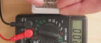
When connecting LEDs, do not forget that they have polarity. To determine the polarity of the LED, you can use a multimeter in continuity mode or an ohmmeter. The use of quenching resistors is justified for powering low-power LEDs; when powering high-power LEDs, you need to use special LED drivers and stabilizers.