How to replace crankshaft bearings without removing the engine
The uninterrupted operation of the power unit depends on the serviceability of each individual element. If a characteristic metallic knock is noticed during its operation, this is usually caused by wear or rotation of the upper/lower sliding element. In this case, replacing the engine liner is carried out quickly in order to protect the engine from major repairs.
How to choose
Regardless of the reason for repairing the engine and replacing the liners, boring the crankshaft is a must. Installation of new parts is only possible on a polished or new mechanism. If there is damage and potholes on only one neck, all elements are processed to achieve a single overall size. Standard parts are installed during the engine assembly line. For example, repair crankshaft liners for VAZ cars are sold in four versions. That is, boring can be done a maximum of four times. Motors for cars such as Moskvich and GAZ have an additional fifth and sixth grinding of up to 1.5 and 1.2 mm, respectively. The best option would be for the person who did the grinding to select the required sizes. Boring may lead to the need to select elements whose size will significantly exceed the previous one. This depends on the depth of the potholes on the necks and their number. The inserts are sold as sets for both types of necks.
What to do if the connecting rod bearing has turned
If you notice symptoms of rotating bearings, you should go to a car service center or to your garage if you are going to replace them yourself, but it is better to turn off the engine and transport them by tow or tow truck, if possible.
Turning the connecting rod bearings is less costly and labor-intensive, if you stop operating when knocking is detected, than turning the main bearings. If you did not pay attention to extraneous knocking noises in the engine and continued to drive in this condition, then, perhaps, the cranked connecting rod bearings will lead to an expensive overhaul of the engine.
Basically, if one connecting rod bearing has turned, then it is replaced with a new one and the repair is complete. In this case, since the connecting rod itself has not been changed, the service life of the repaired crankshaft journal-connecting rod pair will be less than expected.
A desirable step in replacing a connecting rod bearing is to also replace the corresponding connecting rod. It often happens that if the connecting rod bearing is turned, the connecting rod lock breaks.
The optimally effective repair for bearing problems is considered to be boring the crankshaft and replacing the bearings with connecting rods. The crankshaft neck on which the rotated liner sat has nicks and scratches. Therefore, it is necessary to grind the crankshaft. All connecting rod bearings have the same dimensions and are completely interchangeable with each other.
The procedure for replacing connecting rod bearings in a garage:
- We install the car over the pit.
- We install anti-roll bars (shoes).
- Unscrew and remove the exhaust pants.
- If the engine design provides for various suspensions for the gearbox, then unscrew and remove them too.
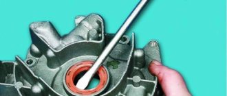
- Remove the oil pan. It is convenient and quick to use a screwdriver for this task.
- Unscrew the oil receiver.
- We unscrew the bridge fastenings and remove it.
- Now you have access to the internal combustion engine crankshaft. Raise the front wheel with a jack and turn the raised wheel in 4th or 5th gear.
- We turn the wheel and set the connecting rods not strictly vertically, but at an angle.
- Next, unscrew the nuts securing the connecting rods and remove the bed in which the connecting rod bearing is seated with tension.
- We remove the second liner from the crankpin (below, the video clearly shows how to do this).
- We look at the removed sliding bearings. Rotated bearings have scratches and mechanical damage, often flattening them.
- We wipe the seats of the beds for the connecting rod bearings and install new bearings in them.
- To prevent the lower bed from being confused (since it can be rotated 180 degrees and installed in a different position), half numbers are stamped on the ends (part of the number is on the end of the bed, the other half of the number is on the connecting rod). There are also numbers stamped on the bottom of the bed, which can be used to compare where the numbers on other beds point.
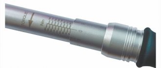
- We do the installation. We tighten the bed nuts with a torque wrench (you cannot overtighten or under-tighten). For different engines there are different tightening torques. There are tables with tightening torques for specific engine parts.
What are crankshaft bearings?
Connecting rod systems The
crankshaft bearings are the plain bearings for the connecting rods that rotate the shaft. The rotation here is a consequence of a microscopic explosion occurring in the combustion chambers of the engine cylinders.
The high speed and heavy loads that arise in this system force the friction of the parts between each other to be minimal, otherwise the engine will fail almost instantly. And this absolutely cannot be allowed. What helps protect the engine?
To prevent this from happening, important engine parts have a thin oil film, which is provided by a special lubrication system of the automobile engine. The appearance of such protection is possible only with fairly high oil pressure
That is, the crankshaft liner parts provide some protection, extending the life of such an important part.
There are connecting rod and main crankshaft bearings. The first are located between its connecting rods and journals. The main ones have a similar role, but their location corresponds to the space between the crankshaft and its passage through the housing of the internal combustion engine.
Repair
Replacing main bearings requires wrench and screwdriver sets and a micrometer. Repair of main liners includes several operations.
- First of all, you need to provide access to the car from below. That is, it should be installed above an inspection hole or on an overpass.
- Remove the negative wire from the battery terminal.
- Next, dismantle the engine sump (this is the easiest way to access; you can start disassembling from above and hang the engine).
- After this, the crankshaft rear oil seal holder is removed from the cylinder block.
- Then remove the camshaft drive cover with the gasket.
- Then remove the chain from the crankshaft sprocket-pulley.
- Next, you need to mark the relative position of the bearing caps relative to the cylinder block and the connecting rods relative to their caps.
- Then, using a 14mm wrench, unscrew the nuts of the connecting rod cover and dismantle it with the liner.
- These operations are repeated for all connecting rods.
- When completed, the lids are moved up.
- Then the main bearings are removed from the caps and connecting rods.
- Next, use a 17 wrench to unscrew the bolts of the crankshaft main bearing caps.
- First, remove the cover of the last one.
- It opens access to the thrust half-rings in the grooves of the rear crankshaft support. They are removed by pressing on the ends with a thin screwdriver.
- These operations are repeated for the remaining bearing caps. In this case, you need to hold the crankshaft. It should be noted that the covers are designated by numbers, and the countdown is from the toe of the crankshaft.
- It is then removed from the crankcase.
- First, the connecting rod bearings are removed, and then the crankshaft main bearings.
- The crankshaft should be inspected for damage. If they are present, the part is changed.
- The connecting rod and main caps are also examined by measuring with a micrometer. The obtained data are correlated with the tabular ones.
- If necessary, parts are polished. In this case, you will need to measure them to calculate the repair size of the liners.
- The crankshaft is cleaned by washing with kerosene and blowing out the cavities.
- Then new bearing shells are installed.
- Thrust half rings are mounted in the grooves of the fifth bearing bed with grooves towards the crankshaft.
- Next, check the gap between these parts. The normal value is considered 0.06-0.26 mm. If it is more than 0.35 mm, use rings of increased thickness.
- The crankshaft is installed in the block, having previously been lubricated with oil.
- Then install the bearing caps and check the freedom of rotation of the crankshaft.
- Connecting rods, liners and covers are installed on it.
- Then the oil pan is installed.
- After this, install the crankshaft holder with the rear oil seal.
- Finally, the remaining parts are installed.
- Finally, the tension of the timing chain, alternator belt and ignition timing are adjusted.
Crankshaft bearing design
What is an engine crankshaft in a car?
The crankshaft sliding bearing is a composite bearing, containing two metal flat half-rings that completely enclose the crankshaft journal (top and bottom). This part performs several elements:
• Holes (one or two) for passing oil into the oil channels in the crankshaft and connecting rod; • Locks in the form of tenons or grooves for pins for fixing the bearing in the crankshaft bed support or in the lower head of the connecting rod; • Longitudinal groove for supplying oil to the hole (performed only on the liner located on the side of the channel - these are the lower main liner and the upper connecting rod liner); • In shoulder thrust bearings there are side walls (collars) for fixing the bearing and limiting the axial movement of the crankshaft.
The liner is a multilayer structure, the basis of which is a steel plate with an anti-friction coating applied to its working surface. It is this coating that ensures reduced friction and long service life of the bearing; it is made of soft materials and, in turn, can also be multi-layered. The coating of the liner, due to its less softness, absorbs microscopic wear particles from the crankshaft, prevents jamming of parts, the formation of scuffing, etc.
According to their design, crankshaft liners are divided into two main groups:
• Bimetallic; • Trimetallic.
Bimetallic bearings have the simplest design. They are based on a steel strip 0.9-4 mm thick (depending on the type and purpose of the part, main bearings are thicker, connecting rod bearings are thinner), on which an anti-friction layer 0.25-0.4 mm thick is applied. This layer is made of copper-lead-tin (bronze), copper-aluminum, copper-aluminum-tin, aluminum-silicon-lead, aluminum-silicon-lead-tin or other soft alloys with an aluminum and copper content of up to 75%, and tin (which acts as a solid lubricant) up to 25%, may also contain small amounts of nickel, cadmium, zinc and other metals.
Trimetallic liners, in addition to the main antifriction coating, have a coating layer 0.012-0.025 mm thick (12-25 microns), which provides protective properties (fights corrosion and excessive wear of the main layer) and improves the antifriction qualities of the bearing. This coating is made from a lead-tin-copper alloy with a lead content of 92-100%, tin up to 12% and copper not more than 3%.
Also, additional layers may be present in sliding bearings:
• The top protective layer of tin is a pure tin coating with a thickness of only 0.5-1 microns, providing protection against corrosion, grease and contamination during transportation, installation and running-in of the liner; • Bottom protective layer of tin - the same layer applied to the outside of the liner (facing the crankshaft supports or the inside of the connecting rod head); • Nickel sublayer (nickel barrier, gasket) - a thin, no more than 1-2 micron layer of nickel between the main anti-friction coating and the cover layer. This layer prevents the diffusion of tin atoms from the coating layer into the main one, which ensures the constancy of the chemical composition of the main antifriction coating. In the absence of a nickel barrier in the base coating, the concentration of tin may increase, which leads to negative changes in the characteristics of the bearing.
The considered structure of sliding bearings is not a standard; many manufacturers offer their own unique schemes and designs. For example, the main antifriction alloy can be applied to the steel base not directly, but through an additional sublayer of aluminum or copper alloy; the coating layer can have a varied composition, including lead-free, etc.
Symptoms of a problem
If you repair the crankshaft yourself, you can save a lot on car service costs. Therefore, it is worth understanding its diagnosis, repair and installation. If repairs are not carried out in a timely manner, the engine may seize, and this can lead to more serious repairs. The following are signs that serve to identify malfunctions:
- when the engine is running, the oil level control light does not go out, which indicates a decrease in oil pressure in the system;
- at medium and high speeds a metallic knock is heard in the engine, which increases with increasing speed;
- engine jams.
The cause of the first two malfunctions is the wear of the main and connecting rod journals. In this case, the distance between the neck and the liner increases, which leads to a decrease in oil pressure. If the distance is too large, the shaft may run out, causing metallic sounds in the engine. If the engine jams, it is better to replace the crankshaft. To diagnose the serviceability of the crankshaft, it should be dismantled and cleaned. It is better to remove the part together with the engine.
After removal, you need to perform a visual inspection of the necks and cheeks, according to which a decision is made on the need for grinding or replacement. No special instruments are needed for inspection; you can tell by touch. If scratches and burrs are found on the journals, the part is sent for boring. Boring can be done 4 times. Each boring increases the dimensions of the liners by 0.25 mm. After dismantling the crankshaft, you need to evaluate the size of the liners and whether they will allow boring. If grinding has never been performed, then the liners have an icon without any numbers.
If cracks are found, the crankshaft must be replaced. You can send it for welding, but usually restored parts last no more than 50 thousand kilometers. After boring, you need to polish the journals. Then the journals and crankshaft need to be washed with gasoline. The oil passages should also be thoroughly cleaned to prevent contamination from entering the bearings. After washing with gasoline, you need to blow out the oil channels using compressed air.
Description of crankshaft bearings
Buy a timing belt
All crankshaft main and connecting rod journals have their own dimensions; we are talking about the parameters that the journals take after the grinding process. The dimensions of these elements must fully correspond to the dimensions of the crankshaft repair liners. Accordingly, when purchasing such spare parts, you must take into account the parameters of your vehicle, because each individual engine has its own dimensions.
For example, if you own a classic VAZ car, you should keep in mind that domestic cars have four different sizes of liners. This means that the crankshaft can, in principle, be bored no more than four times. You also need to take into account that the crankshaft liners also have an outer size, which never changes, but the inner one can be adjusted due to an increase in the thickness of the elements.
Purpose of the inserts
In fact, the crankshaft main bearings, regardless of the markings, act as bearings designed to improve the sliding of the connecting rods. Connecting rods, as you know, are designed to rotate the crankshaft under the influence of a micro-explosion of the combustible mixture in the combustion chambers of the engine. Since the elements periodically wear out, the motorist must promptly remove and replace them, which should also be accompanied by boring the shaft.
It is no secret that when the engine is running, internal components are subjected to high loads and rotation speeds. This means that the motor simply needs to reduce friction, otherwise the unit may fail almost immediately. To ensure that the friction force is significantly lower, all the necessary components inside the motor operate in a micron film, which is oil.
This layer, which envelops the metal components of the unit, is formed only with sufficient pressure of the working fluid. In particular, the film should always be between the crankshaft journal and the liner, as a result of which the friction index is not as high as it could be. Accordingly, the liners, which are made of metal, provide reliable protection that allows you to increase the service life of the shaft as a whole.
Design
It would seem that the crankshaft liner is a common part, but its manufacture is carried out using several different metals.
Accordingly, the liner consists of several layers, which we will consider below:
- the first layer is made from copper, its percentage can be from 69 to 75%;
- the second layer is made from lead, its percentage ranges from 21 to 25%;
- third layer - tin, about 2-4%.
In general, the total thickness of the liner is 250-400 microns. It should be noted that sometimes not copper, tin and lead are used to make the liner, but a specialized aluminum alloy. Labeling in this case will depend solely on the manufacturer.
Kinds
As for the types, the marking here will depend on the type of component.
In general, crankshaft bearings are divided into several groups:
- Indigenous. Regardless of the marking, the main bearings perform similar functions. They are mounted between the crankshaft and the place where this shaft passes through the engine housing.
- Connecting rods. The connecting rod components are located directly between the connecting rods and the shaft journals.
In principle, bearings, both connecting rod and main, are produced for each type of engine, but they all differ in internal diameter. Depending on the engine model, the diameters of the elements will be different, even for the same engine. As a rule, the difference in diameter, that is, the pitch, is 0.25 mm. This means that the size range of parts is compiled as follows: 0.25 mm, 0.5 mm, 0.75 mm, etc.
How and with what force to tighten the connecting rod and main bearings
The internal combustion engine structurally has a large number of associated parts, which experience significant loads during operation of the internal combustion engine. For this reason, assembling a motor is a responsible and complex operation, for the successful implementation of which the technological process must be followed. The performance of the entire power unit directly depends on the reliability of fixation and the accuracy of fit of individual elements. For this reason, an important point is the accurate implementation of the calculated interfaces between mating surfaces or friction pairs. In the first case, we are talking about attaching the cylinder head to the cylinder block, since the cylinder head bolts must be pulled with a strictly defined force and in a clearly designated sequence.
We also recommend reading the article on how to tighten cylinder head bolts. From this article you will learn about the cylinder head tightening torque, the tightening sequence, as well as various nuances during this operation.
As for loaded rubbing pairs, increased demands are placed on the fixation of connecting rod and main plain bearings (main and connecting rod bearings). After engine repair, during the subsequent assembly of the power unit, it is very important to maintain the correct tightening torque of the main and connecting rod bearings of the engine. In this article we will look at why it is necessary to tighten the bearings with a strictly defined force, and also answer the question of what is the tightening torque for the main and connecting rod bearings.
Crankshaft bearing design
The crankshaft sliding bearing is a composite bearing, containing two metal flat half-rings that completely enclose the crankshaft journal (top and bottom). This part performs several elements:
• Holes (one or two) for passing oil into the oil channels in the crankshaft and connecting rod; • Locks in the form of tenons or grooves for pins for fixing the bearing in the crankshaft bed support or in the lower head of the connecting rod; • Longitudinal groove for supplying oil to the hole (performed only on the liner located on the side of the channel - these are the lower main liner and the upper connecting rod liner); • In shoulder thrust bearings there are side walls (collars) for fixing the bearing and limiting the axial movement of the crankshaft.
The liner is a multilayer structure, the basis of which is a steel plate with an anti-friction coating applied to its working surface. It is this coating that ensures reduced friction and long service life of the bearing; it is made of soft materials and, in turn, can also be multi-layered. The coating of the liner, due to its less softness, absorbs microscopic wear particles from the crankshaft, prevents jamming of parts, the formation of scuffing, etc.
According to their design, crankshaft liners are divided into two main groups:
• Bimetallic; • Trimetallic.
Bimetallic bearings have the simplest design. They are based on a steel strip 0.9-4 mm thick (depending on the type and purpose of the part, main bearings are thicker, connecting rod bearings are thinner), on which an anti-friction layer 0.25-0.4 mm thick is applied. This layer is made of copper-lead-tin (bronze), copper-aluminum, copper-aluminum-tin, aluminum-silicon-lead, aluminum-silicon-lead-tin or other soft alloys with an aluminum and copper content of up to 75%, and tin (which acts as a solid lubricant) up to 25%, may also contain small amounts of nickel, cadmium, zinc and other metals.
Trimetallic liners, in addition to the main antifriction coating, have a coating layer 0.012-0.025 mm thick (12-25 microns), which provides protective properties (fights corrosion and excessive wear of the main layer) and improves the antifriction qualities of the bearing. This coating is made from a lead-tin-copper alloy with a lead content of 92-100%, tin up to 12% and copper not more than 3%.
Also, additional layers may be present in sliding bearings:
• The top protective layer of tin is a pure tin coating with a thickness of only 0.5-1 microns, providing protection against corrosion, grease and contamination during transportation, installation and running-in of the liner; • Bottom protective layer of tin - the same layer applied to the outside of the liner (facing the crankshaft supports or the inside of the connecting rod head); • Nickel sublayer (nickel barrier, gasket) - a thin, no more than 1-2 micron layer of nickel between the main anti-friction coating and the cover layer. This layer prevents the diffusion of tin atoms from the coating layer into the main one, which ensures the constancy of the chemical composition of the main antifriction coating. In the absence of a nickel barrier in the base coating, the concentration of tin may increase, which leads to negative changes in the characteristics of the bearing.
The considered structure of sliding bearings is not a standard; many manufacturers offer their own unique schemes and designs. For example, the main antifriction alloy can be applied to the steel base not directly, but through an additional sublayer of aluminum or copper alloy; the coating layer can have a varied composition, including lead-free, etc.
Installing liners without locks
Big and small tricks when installing pistons and connecting rods into an engine
When it comes time to assemble an engine, especially a V-twin, the correct alignment of the pistons and connecting rods, as well as in relation to the cylinder block and crankshaft, can baffle many engine mechanics. With this article we will try to help them.
How to properly install pistons on connecting rods?
If you are assembling a V-shaped engine, then you should keep in mind: if the lower head of the connecting rod has a wider chamfer on one side, then it should face the fillet (rounding) of the crankpin of the crankshaft.
If the connecting rods are intended for use with a crankshaft without clearly defined fillets, then they can be without asymmetrical chamfers. Then the orientation of the connecting rod can be determined by the position of the “locks” of the liners: facing outward of the block or inward (towards the camshaft - if it is located in the camber of the cylinder block).
For example, the “locks” of the SBC and BBC earbuds should face outward. For other earbuds, the “locks” may be directed inward. The location of the “locks” does not have any effect on the operation of the inserts themselves. You just need to orient the connecting rod correctly.
If there are no chamfers on both sides on the lower head of the connecting rod, then the liner must be offset from the fillet of the connecting rod journal so that its edge does not fall on the rounding.
Through holes in the upper and lower connecting rod heads
Often the connecting rod has a through hole on the lower head, which is needed to lubricate the cylinder wall. These holes are not intended to lubricate the camshaft, as some people believe.
It happens that the hole is located only on one side of the lower head of the connecting rod. Such connecting rods must be installed so that the hole in the lower head faces the camshaft (towards the camber of the cylinder block).
The hole in the upper head of the connecting rod (whether it is at the top or at the side - at an angle) serves to lubricate the piston pin. Therefore, its orientation in the engine does not matter.
"Locks" of connecting rod bearings
The “locks” (fixing protrusions) on the liners and the corresponding grooves on the lower head of the connecting rod and its cover are needed only for the correct positioning of the liners. They do not prevent the liners from “rotating”, since the liners are fixed in their “bed” due to the tension that occurs when the fastening bolts of the lower head cover are correctly tightened.
“Correct” liners, when installed properly, protrude slightly beyond the parting line of the lower head. Therefore, after tightening the bolts, they are securely fixed in the “bed”.
Recently, many engines have used “lockless” liners (an example is the Chrysler 3.7L and 4.7L engines). By eliminating operations for machining grooves in the connecting rod and its cover, as well as “locks” on the liners themselves, the costs of their manufacture are reduced. When installing such liners, they must be placed strictly in the middle of the lower head of the connecting rod.
Rice.
1 If in a V-engine, two connecting rods are mounted on one crankpin of the crankshaft, then the side of the lower head of the connecting rod with a narrower chamfer should face the adjacent connecting rod...
Rice.
2 ... in this case, the larger chamfer on the lower head of the connecting rod turns out to be facing the fillet of the crankpin of the crankshaft.
Rice.
3 The fixing protrusion (“lock”) on the liner and the corresponding groove in the lower head of the connecting rod are needed only to correctly install the liners in the connecting rod. “Locks” will never keep the liners from turning in the connecting rod if any violations were made during assembly. For example: the connecting rod lower head bolts are not tightened properly or the hole in the lower head has lost its shape.
Rice.
4 The liners are fixed in the connecting rod only due to the radial force that arises from the tension of the installed liners when the lower head mounting bolts are tightened to the correct torque.
To obtain the required tension, the liner is made slightly longer than its seat. Therefore, when you “hand” install the liner into the “bed”, it will protrude slightly above the plane of the connector. This is how it should be - under no circumstances should you file or trim the edges of the liners! Crush Height Each Half Bearing
- protrusion of the liners above the plane of the connector
Bearing
- liner
Cap
- cover of the lower head of the connecting rod
Radial Pressure
- radial force
Rice.
5 The maximum diameter of the piston must be measured in a strictly defined place, since the piston skirt has a “barrel-shaped” profile and the measurement results based on the height of the piston will vary significantly.
Rice.
6 A through hole on the side surface of the connecting rod (upper head of the connecting rod) (top photo) may indicate a press fit of the pin in the connecting rod. The second photo shows the same connecting rod, but from the outside. But the hole on top of the piston pin (third photo) serves to improve the lubrication of the “floating” piston pin.
Rice.
7 There are usually special marks on the bottom of the piston (for example, an arrow and the inscription “FRONT” - as in the photo) that help to correctly orient the piston when assembling the engine.
Rice.
8 If the pistons are intended for a V-shaped engine, then usually on the “wrong side” of such pistons they are marked “L” - if they are mounted in the left bank of cylinders or “R” - for the right bank of cylinders.
Connecting rod offset
There are engines in which the connecting rod rod is offset relative to the upper or lower heads (if you look at the connecting rod from the side - “in profile”). Similar connecting rods are used in V-shaped engines, in which the left and right rows of cylinders are “staggered”, forward and backward, relative to each other. Depending on the specific engine model, the connecting rod rod may have an offset of 2.5 mm or even more.
If there is any doubt, during installation, note that the upper head of the connecting rod is centered on the piston - in the pin bosses.
Is it necessary to install pistons in the “reverse” direction in engines with counterclockwise rotation?
On a reverse-rotating engine—where the crankshaft rotates counterclockwise when viewed from the front of the engine—the connecting rods are usually installed in the same way as in a conventional engine whose crankshaft rotates clockwise. That is, the larger chamfer of the lower head of the connecting rod will still face the fillet of the connecting rod journal.
Marking features
If bearing parts are worn or damaged and the correct crankshaft clearance cannot be obtained, the situation can be improved by selecting new bearings. If the connecting rods have been bored, then they must be equipped with parts of the corresponding repair sizes of the connecting rod bearings. Usually the selection is entrusted to specialists.
When choosing new connecting rod bearings, they are guided by color markings - you need to look at those parts that were removed from the car. If the elements of old bearings do not have color markings, then look for them on the lower heads. There you need to see a mark in the form of a number - this is the class of the bearing. They also check the letter marks on the crankshaft - they determine the dimensions of the connecting rod journals.
To navigate the bearing selection map, use the markings on the cylinder block. For example, C3 says that you need to install a yellow and green liner. Moreover, any of them can be installed in a lid or in a bed. When selecting new bearings, use the identification color card for marking the connecting rod bearings. So, if you find a letter on the connecting rod journal and a number on the connecting rod (for example, D4), then according to this map you need a blue bearing. Naturally, you need to remember that colors may be different for different engines.
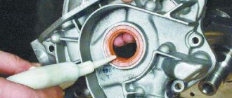
Replacing the crankshaft oil seal
The main sign of the need to replace the oil seal is contamination of the engine compartment. A breakdown occurs when the seal of the unit is broken, causing lubricant mixed with oil to leak through the damaged oil seal. As a result, when it gets on the rotating parts, the mixture is sprayed throughout the engine compartment.
In particular, a signal that an urgent replacement of the front oil seal liners is necessary is the direct contact of oil on the pulley and its further splashing in the front part of the engine. If oil leaks in the rear oil seal, splashing occurs on the flywheel in the clutch housing. Reasons for replacement:
- natural wear and tear;
- skewed installation, which may cause cracks on the body;
- mechanical damage;
- damage to surface integrity as a result of severe engine overheating;
- marriage.
You can replace crankshaft oil seals yourself; this will not only significantly save time and money spent on repairs in the workshop, but also gain invaluable experience. Replacing the crankshaft oil seal is a standard procedure to ensure optimal engine performance.
Oil seals are a type of cuff that acts as seals on moving parts. It would be most correct to call the crankshaft oil seal a reinforced cuff. Its role in the functioning of the engine is very significant, and therefore any failures in the stable operation of the crankshaft oil seal will lead to undesirable consequences. Even if the degree of its displacement from the standard place is insignificant, oil will begin to leak in the car.
According to statistics, the installation of a new oil seal should be done at least once every 3 years. However, oil seal bearings may need to be replaced much sooner. It all depends on the general condition of the parts and the conditions under which the car is used.
Main liners
Engine main bearings are designed to house the engine crankshaft in the engine block and allow the crankshaft to rotate.
What are engine main bearings used for?
Engine main bearings are essentially plain bearings and ensure reliable rotation of the crankshaft under significant speeds and loads. The design of the crankshaft and bearings provides for the supply of oil to the interface between the bearing and crankshaft journals in order to form an oil film and reduce friction.
The liner itself remains motionless relative to the engine, since it is fixed in places specially prepared for this, called beds. Additionally, a special anti-friction coating is applied to the surface of the liner.
How often to change engine main bearings?
The design of the main engine bearings remains traditional over time - this is a plain bearing, which is a bent metal sheet of a certain radius with an anti-friction coating applied.
Main bearings work in very difficult conditions. Therefore, very serious requirements are placed on the liners, as well as their installation. Theoretically, the durability of the liners is comparable to the service life of the engine, i.e. more than 200 thousand km. The need to replace the main bearings arises when they are worn out (usually due to insufficient lubrication or poor-quality material). In case of insufficient lubrication, due to an increase in the friction force between the liner and the journal, the liners may be torn from their place in the cylinder block, and the block itself may be damaged.
The need to replace the main bearings also arises when repairing (grinding) the crankshaft journals, since in this case the size of the journals changes. In this case, it is necessary to install inserts of a different size. Poor engine assembly, non-compliance with manufacturing technology and dimensions of individual parts, engine overheating and changes in its geometric parameters can also lead to wear or damage to the main liners.
Causes of wear
As mentioned above, when the engine is running, each main liner of the engine is constantly exposed to a frictional force, tending to displace it from its original location. In the original state of a working engine, the strength of the parts is calculated with a margin in order to withstand such loads. For power units up to 200 hp. With. The stress on the liner ranges from 0.1 to 1 kgf. The magnitude of its force is proportional to the load at a constant coefficient of friction.
In addition, the main liners are protected by the fact that they operate in liquid friction mode. This is ensured by the use of oil, which creates a film between the shaft journal and the working surface of the liner. In this way, the parts in question are protected from direct contact and a minimum friction force is achieved. The formation of an oil film is determined by the speed of mutual movement of the rubbing parts. As it increases, the hydrodynamic friction regime increases. This term refers to an increase in the efficiency of pulling the film into the gap and an increase in its thickness as a result. However, as the speed of the parts increases, the amount of heat generated during friction also increases, and, consequently, the oil temperature increases. This leads to its liquefaction, resulting in a decrease in film thickness. Therefore, for optimal operation it is necessary to achieve a balance between the considered processes.
If the integrity of the oil film is damaged, the friction coefficient increases. As a result, the cranking torque generated by the crankshaft increases even under constant load.
However, sometimes the opposite situation occurs when increased loads for some reason lead to a decrease in the thickness of the oil film. Also, as a result of this, the temperature increases, especially in the friction zone. As a result, the lubricant dilutes, further reducing the thickness.
These processes can be interconnected and manifest together. That is, one of them may be a consequence of the other.
Therefore, the cranking torque is significantly influenced by the viscosity of the oil. The relationship between these factors is directly proportional, that is, the higher it is, the greater the friction force. In addition, with high viscosity, the oil wedge increases. However, if the viscosity is excessive, the oil does not flow into the friction zone in sufficient volumes, as a result of which the thickness of the oil wedge decreases. As a result, the effect of oil viscosity on bearing rotation cannot be determined unambiguously. Therefore, another property of this material is taken into account: lubricity, which is understood as the strength of its adhesion to the working surface.
The friction coefficient is determined by the roughness and accuracy of the geometry of the contacting surfaces, as well as the presence of foreign particles in the lubricant. In the case of the presence of particles in the lubricant or surface irregularities, the film is disrupted, as a result of which a semi-dry friction mode appears in some areas. Moreover, these factors manifest themselves most intensively at the beginning of the vehicle’s operation, when parts are running in, so rubbing parts are especially sensitive to overloads during this period.
In addition, the crankshaft main bearings rotate due to insufficient force holding them in place. It may be due to improper installation or be a consequence of wear as a result of the influence of the turning torque.
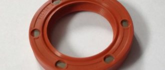
Why do you need to replace half rings and when is it necessary?
Half rings are consumables and are subject to wear. When they wear out, the crankshaft begins to move horizontally, which accelerates the wear of the half rings. Ultimately, the half rings become completely unusable (erased) and the crankshaft loses all fixation, creating a threat, first of all, to the entire piston group. In addition, the crankshaft can grind the cover that covers it and render the support bearings unusable. These parts are cast together with the block, which indicates a high probability of replacing the latter. To prevent this, it is necessary to carry out timely diagnostics of faults and, if necessary, change the half rings.
Diagnostics are performed after 120 thousand kilometers and begin with an external inspection of the engine. The presence of an oil leak is the first, but not the main sign. The fact is that when play appears, the crankshaft can squeeze out the oil seal, which will very quickly lead to a leak of engine oil. However, oil leaks do not always occur precisely for this reason. It is quite possible that the oil seal simply became unusable due to natural wear and tear.
Take the installation tool and, resting it on the generator, try to shake the crankshaft pulley. The permissible axial play should not exceed 0.35 mm. Also, have someone press the clutch pedal. If the crankshaft is pushed forward, then this is the most obvious sign of a malfunction of the crankshaft half rings.
Before carrying out the replacement, purchase new engine oil, as this may be an excellent opportunity to replace it, the oil pan gasket and the half rings themselves.
Work order
1. Place the car on a pit or overpass and prevent it from moving.
2. Unscrew the engine protection and remove it. Drain the engine oil.
3. Unscrew all bolts securing the oil pan and remove it along with the gasket.
4. Unscrew the bolts for securing the main bearing cap and remove it.
5. Install the new half rings so that its ends rest against the ends of the old one. To make the task easier, move the shaft with a screwdriver.
6. Push out the old element using the new one. The new part should fit in absolutely freely.
That's all. This completes the replacement of the crankshaft half rings. Reassemble all components in reverse order. When installing a new pan gasket, be sure to treat it with a sealant that can withstand high temperatures. After assembly, fill in new oil.
We remove the crankshaft to replace it or replace the bearings.
1. Place the car on an inspection hole or overpass (see “Preparing the car for maintenance and repair”).
2. Remove the engine sump (see “Engine sump - removal and installation”).
3. Remove the holder with the oil seal from the cylinder block (see “Crankshaft rear oil seal - replacement”).
4. Remove the camshaft drive cover with the sealing gasket and the chain from the crankshaft sprocket (see “Timing chain - replacement”).
5. We mark the relative position of the connecting rods relative to their caps and the main bearing caps relative to the cylinder block.
14 mm socket wrench
Unscrew the two nuts securing the connecting rod cover.
7. Remove the connecting rod cover along with the liner.
8. Disconnect the remaining connecting rods from the crankshaft and move them upward.
We remove the liners from the connecting rods and their caps.
17 mm socket wrench
loosen the bolts securing the crankshaft main bearing caps.
10. After unscrewing the two bolts, remove the rear main bearing cover. Two thrust half-rings are installed in the grooves of the rear crankshaft support. Front ring A
- steel-aluminum, and the rear
B
- metal-ceramic. The rings can be removed by pressing on their ends with a thin screwdriver.
11. Unscrew the bolts of the remaining main bearing caps, keeping the crankshaft from falling. We remove the covers one by one and remove the crankshaft from the crankcase. All cover liners (except for the third one), installed in the main bearing beds, have a groove. The main bearing caps have marks corresponding to their serial number (counted from the toe of the crankshaft), facing the left side of the cylinder block. The fifth cover has two marks spaced along the edges.
Mark on the first main bearing cap
12. To replace, remove the crankshaft main bearing shells from the cylinder block and covers.
Note
If there are any cracks on the journals or cheeks, the crankshaft must be replaced.
13. We measure the diameters of the main and connecting rod journals with a micrometer and compare them with the data given in the table. 8.1.1. If wear or out-of-roundness is more than 0.03 mm, then the journals must be ground in a specialized workshop where the necessary equipment is available (the axial runout of the main surfaces of the crankshaft must also be checked there). After grinding, we re-measure the diameters of the crankshaft journals to determine the repair size of the liners.
Main (A) and connecting rod (B) crankshaft bearings
Table 8.1.1.
Crankshaft journal diameters
| Nominal size, mm | Repair (reduced) dimensions, mm | |||
| Crankpins | ||||
| Root necks | ||||
Installation
1. Wash the crankshaft in kerosene and blow through its internal cavities with compressed air. We install new crankshaft main bearing shells of nominal or repair size. On the outer cylindrical surface of the liners there are numbers stamped indicating the repair size: 025 - the first repair, for the crankshaft journal, reduced in diameter by 0.25 mm. Accordingly, for the second, third and fourth repair sizes the values will be: 050, 075, 100. It is easy to distinguish connecting rod bearings from main bearings. The upper main bearings (except for the middle one) have annular grooves. In addition, the middle support liners are wider than the others. The connecting rod bearings are all identical and interchangeable, their diameter is less than the diameter of the main bearings. To increase the contact area, there are no annular grooves on the connecting rod bearings.
2. We install thrust half-rings in the grooves of the fifth main bearing with grooves towards the crankshaft. Half rings are manufactured in normal thickness (2.310-2.360 mm) and increased thickness (2.437-2.487 mm).
3. We check the axial clearance between the thrust half-rings and the thrust surfaces of the crankshaft, which should be in the range of 0.06-0.26 mm. If the gap exceeds the maximum permissible (0.35 mm), replace the thrust half-rings with new ones, increased by 0.127 mm.
4. Lubricate the connecting rod and main journals of the crankshaft with engine oil and install the shaft into the block.
5. In accordance with the marks, install the main bearing caps and tighten their mounting bolts to a torque of 68.4-84.3 Nm. Check the free rotation of the shaft.
6. Install connecting rods with liners and covers on the crankshaft. Tighten the fastening nuts to a torque of 43.4-53.5 Nm.
7. Install the engine sump (see “Engine sump - removal and installation”).
8. Install the holder with the oil seal on the cylinder block (see “Crankshaft rear oil seal - replacement”).
9. Installation of the remaining removed parts is carried out in reverse order.
10. Adjust the chain tension (see “Timing chain - replacement”).
11. Adjust the tension of the generator drive belt (see “Generator drive belt - tension adjustment and replacement”).
12. Check and, if necessary, adjust the ignition timing (see “Ignition timing - checking and adjustment”).
The crankshaft is one of the most expensive and critical structural elements of an internal combustion engine. It is this design that converts the reciprocating motion of the pistons into torque. The crankshaft (crankshaft) takes on all the variable loads that arise through the force of gas pressure and inertial forces that move and rotate certain masses.
As a rule, the crankshaft of an internal combustion engine is a solid structural element. This is why the crankshaft should be called a part. This part is made using forging from steel, as well as using casting from cast iron. On turbocharged and diesel engines, crankshafts are usually installed durable and steel.
For a car enthusiast, a necessary element of knowledge about the crankshaft will be the study of its diagram and structure. If we talk about the design of this device, then it combines several connecting rod and main journals, which are connected to each other using cheeks. As a rule, there are always one unit more main journals, and the shaft itself, which has such an arrangement, is called full-support. The main journals themselves have a significantly larger diameter than the connecting rod journals.
In the direction opposite to the connecting rod journal, the continuation of the cheek is the counterweight. The main purpose of the counterweight is to balance all weight categories of pistons and connecting rods. This procedure ensures completely smooth operation of the internal combustion engine. The connecting rod neck, which is located between the two cheeks, is called the knee. This type of knee is placed depending on the order of operation, the location and number of cylinders, and also depending on the engine stroke. It is the position of these knees that should completely ensure balance in the engine, uniform ignition of the air-fuel mixture, and also ensure the smallest torsional vibrations and bending moments.
The crankpin itself is designed and functions as a supporting surface for a specific connecting rod.
The most loaded of the entire crankshaft design is the place where the transition from the main or connecting rod journal to the cheek is located. In order to reduce the stress concentration, it is necessary to make a transition from neck to neck with a certain radius of curvature. The fillets (radius of curvature) in their entirety can increase the length of the crankshaft. And in order, on the contrary, to reduce the length, it is necessary to perform this radius of curvature with a certain recess into the neck or cheek.
In the bearings, rotation of the crankshaft, and in the connecting rod journals, occurs through plain bearings. For this type of bearings, various detachable thin-walled liners are used, made from steel strips on which an antifriction layer has been applied. The rotation of the liners, which are located around the neck, is prevented by a protrusion that fixes them in the support. In order to prevent axial movements of the crankshaft, it is necessary to use a thrust bearing. It will be installed on the extreme or middle molar neck.
Device features.
On the sides of the third main bearing support cover there are thrust half rings. To explain it in common parlance, these half rings are installed between the crankshaft cheeks and the support of the entire block. These kind of half rings, in fact, keep the entire crankshaft from moving axially, play.
With a certain operating time of the vehicle, the half-rings decrease, while the backlash increases. However, this is not the most dangerous thing for a car enthusiast. Problems can arise if, over time, the rings wear out to a certain extent, as a result of which they stop all attempts to hold on and fall into the crankcase pan. This is a huge problem, since in the absence of a ring between the block cover and the crankshaft, the crankshaft itself begins the direct process of grinding the support cover.
The unpleasantness of this situation that has arisen is very great. It consists in the fact that the block bearing support cover itself is cast together with the block itself to increase accuracy. Thus, if the crankshaft play is not determined in time, it may be necessary to replace the entire crankshaft and block. In addition, with increased crankshaft play, the crankshaft rear oil seal is constantly squeezed out, as well as oil leakage. The rear crankshaft oil seal itself is located behind the flywheel. Thus, in order to completely replace this device, the car owner will have to carry out a huge amount of repair work.
Checking technical condition and repairs.
How to determine that a given part has reached the end of its service life? It's very easy to do. First you need to take the assembly. Afterwards, you need to rest it on one side against the body itself, and on the other hand press on the generator pulley in the crankshaft. In this case, the axial clearance of the crankshaft should not be the maximum permissible clearance - 0.35 millimeters.
In addition, you need to ask someone to depress the clutch, while watching the crankshaft. If in such a situation a very strong play is noticeable, then it is necessary to immediately replace all half rings. This is explained by the fact that if the half ring falls out, the crankshaft will grind down the groove on the bearing cap itself, and the new ring simply will not stay in this place. In general, it is recommended to check the play after every 100 thousand vehicle mileage.
Replacing half rings is quite simple. It is necessary to purchase half rings, sealant and an oil pan gasket.
Since it will be necessary to drain the oil from the engine itself, the work called replacing the half rings can be combined with the work of changing the oil. In addition, you can clean the oil receiver and pan. An interesting fact is that the half rings installed at the manufacturer’s plant are completely different: made of steel and aluminum, as well as metal and ceramics. On sale, all half rings are the same. One side is steel, and the other has an anti-friction layer. In addition, there may be other half rings that are metal-ceramic on both sides.
That's it, you can replace the crankshaft half rings. First you need to remove the engine protection and completely drain the engine oil. All 16 oil pan mounting bolts must be unscrewed and the pan itself removed. The two bolts securing the middle main bearing cover also need to be unscrewed, so that it can be removed. After all the work done, you can safely install new half rings. It is important that the grooves of the half rings must face the thrust surfaces of the crankshaft
(there is an anti-friction layer on the side of the grooves). That's it, all that remains is to move the shaft left and right using screwdrivers in order to evaluate the axial movement, which should not exceed 0.26 millimeters. That's it, the repair work has been successfully completed.
Subscribe to our feeds at
The crankshaft is cast from high-strength cast iron and has five support (main) journals and four connecting rods. The surfaces of the necks are hardened by high frequency currents to a depth of 2-3 mm. At the rear end of the crankshaft there is a socket for installing the gearbox drive shaft bearing.
The connecting rod and main journals of the crankshaft are connected by channels through which oil is supplied to lubricate the connecting rod bearings. The technological outlets of the channels are closed with cap plugs, which are pressed in and caulked at three points for reliability.
The axial movement of the crankshaft is limited by two thrust half-rings installed in the cylinder block on either side of the rear main bearing. A steel-aluminum half-ring is placed on the front side of the bearing, and a metal-ceramic half-ring (yellow) is placed on the rear side. Both types of half rings have the same dimensions and are made with a thickness of 2.31-2.36 mm and 2.437-2.487 mm (repair). When assembling the engine, the half rings are selected in thickness so that the axial free play (play) of the crankshaft is within 0.06-0.26 mm.
To extend the service life of the crankshaft, it is possible to regrind the crankshaft journals when their surfaces are worn or damaged. By grinding, the diameters of the main journals are reduced by 0.25; 0.5; 0.75 and 1.00 mm. In this case, the diameters of the main journals after grinding should be respectively equal to 50.545-0.02; 50.295-o,og; 50.045-o.02; 49.795-0.02 mm, and the diameters of the connecting rod journals are 47.584-0.02; 47.334-0.02; 47.084-o,o2; 46.834-o.02 mm.
The crankshafts of engines 2103 and 2106 differ from the crankshafts of engines 2101 and 21011 in the crank radius increased by 7 mm. Therefore, the crankshafts of engines 2103 and 2106 are marked “2103” on one of the cheeks of the middle main journal to distinguish them.
The crankshaft is balanced separately from the flywheel, making these parts individually interchangeable.
Main and connecting rod bearing shells.
Thin-walled, bimetallic, steel-aluminum liners. The shells of the 1st, 2nd, 4th and 5th main bearings have a groove on the inner surface (since 1987, the lower shells of these bearings are installed without a groove). The shells of the central (3rd) main bearing differ from the other shells by being wider and lacking a groove on the inner surface. All connecting rod bearing shells are without grooves, identical and interchangeable.
Each bearing shell consists of two identical halves. They are kept from turning by protrusions that fit into the corresponding grooves of the connecting rod or main bearing.
The nominal thickness of the main bearing shells is 1.831-0.007 mm, and the connecting rod bearings are 1.730-0.007 mm. Inserts of repair sizes are supplied under the crankshaft journals, reduced in diameter by 0.25; 0.50; 0.75; 1.00 mm. The thickness of the repair liners for connecting rod bearings is 1.855-о.оо7; 1.980-0.007; 2.105-o,oo7; 2.230-о.оо7 mm, and radicals 1.956-о.оо7; 2.081-o,oo7; 2.206-o,oo7; 2.331-о,оо7 mm.
Flywheel
. Cast from cast iron and equipped with a steel ring gear for starting the engine with a starter. The crown is pressed onto the flywheel while hot. To increase wear resistance and strength, the teeth of the crown are hardened with high frequency currents.
The flywheel is attached to the crankshaft flange with six self-locking bolts, under which one common washer is placed. It is unacceptable to replace these bolts with any others. The bolt arrangement is such that the flywheel can only be attached to the shaft in two positions. It must be installed so that the mark - a cone-shaped hole - is located against the connecting rod journal of the 4th cylinder. The mark is used to determine the TDC in the 1st and 4th cylinders. The flywheel is centered with the crankshaft by the front drive shaft bearing
If wear or out-of-roundness is more than 0.03 mm, then the crankshaft journals must be ground in a specialized workshop where the necessary equipment is available (the axial runout of the main surfaces of the crankshaft must also be checked there). After grinding the crankshaft, we re-measure the diameters of the crankshaft journals to determine the repair size of the liners.
Installing a crankshaft on a VAZ 2107 car
1. We wash the crankshaft in kerosene and blow through its internal cavities with compressed air. We install new crankshaft main bearing shells of nominal or repair size. On the outer cylindrical surface of the liners there are numbers stamped indicating the repair size: 025 - the first repair, for the crankshaft journal, reduced in diameter by 0.25 mm. Accordingly, for the second, third and fourth repair sizes the values will be: 050, 075, 100. It is easy to distinguish connecting rod bearings from main bearings. The upper main bearings (except for the middle one) have annular grooves. In addition, the middle support crankshaft bearings are wider than the others. The crankshaft connecting rod bearings are all identical and interchangeable; the diameter of the connecting rod bearings is less than the diameter of the main bearings. To increase the contact area, there are no annular grooves on the connecting rod bearings. 2. We install thrust half-rings in the grooves of the fifth main bearing bed with grooves towards the crankshaft. Half rings are manufactured in normal thickness (2.310-2.360 mm) and increased thickness (2.437-2.487 mm). 3. We check the axial clearance between the thrust half-rings and the thrust surfaces of the crankshaft, which should be in the range of 0.06-0.26 mm. If the gap exceeds the maximum permissible (0.35 mm), replace the thrust half-rings with new ones, increased by 0.127 mm. 4. Lubricate the crankshaft connecting rod and main journals with engine oil and install the crankshaft into the cylinder block. 5. In accordance with the marks, install the main bearing caps and tighten their mounting bolts to a torque of 68.4-84.3 Nm. Check the free rotation of the crankshaft. 6. Install connecting rods with liners and covers on the crankshaft. Tighten the fastening nuts to a torque of 43.4-53.5 Nm. 7. Install the engine sump on the VAZ 2107 car (see “Engine sump - removal and installation”). 8. Install the holder with the oil seal on the cylinder block (see “Crankshaft rear oil seal - replacement”). 9. Installation of the remaining removed parts on the VAZ 2107 car is carried out in the reverse order. 10. Adjust the timing chain tension (see “Timing chain - tension adjustment”). 11. Adjust the tension of the generator drive belt (see “VAZ 2107 generator drive belt - tension adjustment and replacement”). 12. On the carburetor engine of a VAZ 2107 car, we check and, if necessary, adjust the ignition timing
Geometry
Naturally, the sizes of connecting rod bearings are different for different internal combustion engines. The most basic parameter is the oil gap. It is equal to the difference between the inner diameter of the liner and the diameter of the shaft. Another important indicator is the size of the oil gap. If the gap is very large, then the oil flow increases, which reduces the heating of the bearing. But oil also causes uneven load distribution, which increases the likelihood of bearing failure due to fatigue. A large gap will result in operating noise and vibration. A small gap will cause the engine oil to overheat and reduce viscosity.
The landing tension is needed to ensure a reliable fit of the VAZ connecting rod bearing in its socket. Reliably and firmly seated bearings are in even contact with the surface of the seat - this will prevent the possibility of bearings moving during operation. Effective heat dissipation is also ensured.
Boring
All connecting rods are removed after sequentially checking the clearances, and the crankshaft is also dismantled and ground. Boring is possible only on special equipment - a centripetal, which is rarely found among ordinary car owners. Therefore, here you will need to contact specialists. After grinding, the crankshaft liners of the appropriate size are selected. Here you cannot do without a tool such as a micrometer and trying on selected elements. Next, all crankshaft parts are installed in the reverse order and the caps on the main bearings are screwed on.
It is worth noting some features of the reverse installation of connecting rods and bearings. The latter are pre-lubricated with oil, and the lids must also be screwed on. Compared to the preparatory work carried out, installation takes much less time. At the same time, we should not forget about the operation of the crankshaft, which is characterized by high loads, as well as its high cost. Everything possible must be done to increase the period of operation. The main role here is played by grinding carried out at the appropriate time. This procedure ensures the smoothness of the necks and prepares them for further use.
Installation procedure
Most often, these elements are installed in auto repair shops, where experienced specialists work. However, if a person has certain repair skills and is good with tools, then you can try to install the crankshaft elements yourself. To do this, you must follow the following procedure:
- The gap between the shaft and the liner is checked. Plastic wire is used here. It is tightened with a force of 51 newton per meter and after that the existing gap is determined by the degree of flattening of the wire. If it is larger than the nominal value, then the liner needs to be replaced.
- All connecting rods are removed from the racks, the crankshaft is dismantled and bored. Then the repair element is selected. These procedures should be performed on a centripetal, and it is also important to have a micrometer.
- After selecting the element, the crankshaft is reinstalled. The components are inserted into their seats and the main bearing caps are screwed on.
- The crankshaft and connecting rods are put back. The inserts are lubricated with oil and their covers are screwed on. As a result, the process is completely completed, the liners will work for a long time.
Direct installation of such elements takes a relatively short amount of time compared to preparatory measures and additional work. This means that with a strong desire and appropriate skills, anyone can insert earbuds on their own.
This is interesting: What to do if the Chevrolet Cruze does not start, how to fix it
Popular on the site
17 Dec
Auto News
2 759
2022 Kia Sportage. When will the new body appear in Russia?
On the page are the first details about the new Kia Sportage body of the 2021 model year, possible configurations and prices, release date in Russia, photos, technical specifications and video test drive of the new model.
28 Jan
Automotive software Repair/operation manuals
941
Nissan Qashqai 2 2.0 — Do-it-yourself replacement of spark plugs (photo report)
Replacing spark plugs on a modified MR20DD Qashqai 2 engine ( J11
) 2.0 l. according to the regulatory deadlines, it should be carried out over a mileage of 30,000 km or once every 24 months. Since this Qashqai, the second generation, was released not so long ago, it has a different, improved engine (a naturally aspirated engine with an aluminum cylinder block with a high compression ratio), unlike its counterparts, it uses more modern, iridium spark plugs.
18 Dec
Electronics and equipment Electrical circuits
894
2022 Jeep Grand Cherokee. Release date of the new body in Russia
Development of the fifth-generation 2022 Jeep Grand Cherokee began with the creation of a new platform. The basis was taken from the Giorgio “trolley”, currently used on the Alfa Romeo Stelvio and Giulia.
16 Dec
Repair Cooling system
651
Toyota Avensis - DIY radiator replacement
Before we begin the replacement, let's say a few words about the new radiator and the tool. The tools you will need are: several screwdrivers, a standard set of keys and an empty container for antifreeze.
29 Dec
Tuning Car tuning
634
Mansory Body Kit makes a Rolls-Royce Cullinan look good in white
Unlike Bentley, which has made several versions of its big boy, Rolls-Royce is in no hurry to fix anything. But fortunately, many clients are wealthy enough to afford a complete makeover. The Mansory body kit actually came out much earlier, at the 2022 Geneva Motor Show.
04 Feb
Auto News
590
2022 Genesis G90. Everything you need to know
The Genesis G90 may be the best luxury bargain to date, offering flagship levels of refinement and performance at a significantly lower price than its more established competition. For 2022, the G90 will receive its first update since the sedan's flagship debuted as a 2017 model, and it includes significant styling updates but only minor interior and driving changes.
24 Dec
Repair Electronics and equipment
575
Symptoms of a faulty engine control unit (ECU)
The engine control unit (ECU), also called the engine control module or transmission control module, is one of the most important components found on almost all modern vehicles.
09 Jan
Articles Engine and its components Ignition system
575
Glow plug relay - how to check its functionality? + Video
Each car has its own glow plug relay circuit. It, like every part, can fail and will have to be replaced. To deal with the rather serious question of how exactly to make a replacement, you need to start with the basics.
10 Feb
Repair Electronics and equipment
559
Skoda Karoq - Unable to register with Skoda Connect
The vehicle cannot be registered when using ŠKODA Connect services. There is no need to update data in the mobile app or on the ŠKODA Connect internet portal.
08 Feb
Reviews / Test drives Articles
558
Best Spark Plugs for Your Car (Review and Buying Guide)
A spark plug is a device or component in your car that is there to supply current from the ignition system to the combustion chamber of the engine. It is used to ignite compressed air or fuel with an electric spark when combustion pressure is present in the engine.
Questions about choosing and replacing crankshaft liners
When selecting sliding bearings, it is necessary to take into account the engine model, wear of associated parts and the presence of repair liners. As a rule, liners are made for one model range or even one engine model, so they cannot be replaced with parts from another engine (with rare exceptions). Also, you cannot use liners without taking into account the wear of the crankshaft journals, otherwise the repair will result in even bigger problems.
Before choosing the repair size of bearings, you need to determine the wear of the crankshaft journals and other associated parts (beds, connecting rod heads, although they are less subject to wear). Usually, the wear of the journals occurs unevenly, some of them wear out more intensively, some less, however, for repairs, a set of identical liners is purchased, so all journals must be ground down to the same size. The choice of the value to which the crankshaft journals will be ground depends on the availability of bearings of certain repair sizes suitable for this particular engine. For engines with low mileage, repair sizes of +0.25 or +0.5 are selected; for engines with significant mileage, it may be necessary to grind down to repair size +1.0; in older engines, even more - up to +1.5. Therefore, for new engines, liners are usually produced in three or four repair sizes (up to +0.75 or +1.0), and for old engines you can find liners up to +1.5.
The repair size of the crankshaft liners must be such that when assembling the engine, a gap remains within 0.03-0.07 mm between the crankshaft journal and the bearing surface. With a smaller gap, there is a high risk of jamming; with a larger gap, the crankshaft runout increases, the wear rate of parts and the overall noise of the power unit increases.
With the correct choice of sleeve bearings for the crankshaft, the engine, even with high mileage, will operate efficiently and effectively in various modes.
Features of operation
During engine operation, the liners are subject to constant loads due to mutual friction of these parts. Therefore, the installation of the main bearings must be carried out with reliable fixation to avoid their displacement by the rotating crankshaft. To achieve this, measures are taken:
- Firstly, they take into account the characteristics of friction of the parts in question, which manifests itself when they slide against each other under load. Its value is determined by the friction coefficient and the magnitude of the load on the interacting parts. Therefore, to ensure reliable retention of the liners, the impact of the crankshaft on them should be reduced. For this purpose, the coefficient of friction is reduced by using antifriction materials that are applied to the surface of the liners.
- Secondly, the main liners are mechanically held in place. Two methods are used for this. These elements are installed with interference specified structurally. In addition, on each of them there is an additional element called a tendril, which also serves for holding.
You need to know the dimensional parameters in order to ensure proper interference and correctly install the main bearings. The dimensions of these elements are selected based on the diameter of the bed. According to this parameter, the liners are divided into size groups, the designation of which is contained in the marking.
Based on size, crankshaft main liners are divided into nominal and repair. There are four repair sizes with a difference of 0.25 mm. They are used if replacement is carried out for a ground crankshaft in accordance with its dimensions.
Types and sizes
VAZ crankshaft liners act as protective elements that prevent premature wear of mating parts. Depending on their location, they are divided into two types: main and connecting rod. The latter, as mentioned earlier, are located on the journals of the shaft, the main ones are located on the crankshaft at the point where it passes through the internal combustion engine and have a similar purpose. Different types of power devices require the use of appropriate elements; first of all, the internal diametrical size must be selected.
Repair parts both differ from each other and have significant differences compared to the new elements that are equipped with new cars at factories. The parameters differ by at least a quarter of a millimeter; all subsequent options go through a similar step.
What are plain bearings
To better understand why engine bearings need to be tightened to a certain torque, let's take a look at the functions and purpose of these elements. Let's start with the fact that these sliding bearings interact with one of the most important parts of any internal combustion engine - the crankshaft. In short, the reciprocating motion of the piston in the cylinder is converted into rotational motion precisely thanks to the connecting rods and crankshaft. As a result, torque appears, which is ultimately transmitted to the wheels of the car.
The crankshaft rotates constantly, has a complex shape, experiences significant loads and is an expensive part. To maximize the service life of the element, connecting rod and main bearings are used in the crankshaft design. Taking into account the fact that the crankshaft rotates, as well as a number of other features, conditions are created for this part that minimize wear.
In other words, the engineers abandoned the decision to install conventional ball or roller bearings in this case, replacing them with main and connecting rod bearings. Main bearings are used for the crankshaft journals. The connecting rod bearings are installed at the junction of the connecting rod with the crankshaft journal. Often, main and connecting rod bearings are made according to the same principle and differ only in the inner diameter.
For the manufacture of liners, softer materials are used compared to those from which the crankshaft itself is made. The liners are also additionally coated with an anti-friction layer. Lubricant (motor oil) is supplied under pressure to the place where the liner is connected to the crankshaft journal. The specified pressure is provided by the oil pump of the engine lubrication system. In this case, it is especially important that there is the required clearance between the crankshaft journal and the plain bearing. The quality of lubrication of the rubbing pair, as well as the engine oil pressure in the engine lubrication system, will depend on the size of the gap. If the gap is increased, then the lubricant pressure decreases. As a result, rapid wear of the crankshaft journals occurs, and other loaded components in the internal combustion engine also suffer. In parallel with this, a knock appears in the engine.
We add that a low oil pressure indicator (in the absence of other reasons) is a sign that the crankshaft needs to be ground, and the engine liners themselves need to be changed taking into account the repair size. For repair liners, an increase in thickness of 0.25 mm is provided. As a rule, there are 4 repair sizes. This means that the diameter of the repair liner in the last size will be 1 mm higher. less compared to standard.
We also recommend reading the article about when and why you need to bore the crankshaft. From this article you will learn about what engine crankshaft grinding is, why this procedure is necessary and how it is performed.
The plain bearings themselves consist of two halves, in which special locks are made for proper installation. The main task is to create a gap between the shaft journal and the liner, which is recommended by the engine manufacturer.
Connecting rod bearing
Connecting rod bearings are designed to reduce friction and wear in the moving connecting rod - crankshaft journal. Tractor connecting rods mainly use plain bearings.
Connecting rod bearings have thin-walled steel liners filled with anti-friction alloy. For carburetor engines, a copper-non-nickel sublayer is applied to the steel strip, on top of which a thin layer of babbitt is poured. An oil channel runs through the body of the connecting rod along its entire length, through which oil is supplied under pressure from the lower head of the connecting rod to the upper one. A bushing is pressed into the lower part of this channel, metering the flow of oil into the upper head of the connecting rod.
Connecting rod bearings are generally plain bearings. Needle bearings and rolling bearings are used only for the smallest engines. For most diesel engines (except for large low-speed ones), the connecting rod rod and piston head are made in one piece.
| Connecting rod of a single-row trunk engine assembled. |
The connecting rod bearings are lubricated with oil, which is supplied under pressure from a hole in the crankpin of the crankshaft.
Connecting rod bearings are bored on a lathe or on special devices (Fig.
The connecting rod bearing is lubricated and cooled by oil coming from the main bearings through the channels of the crankshaft. Through the holes in the lower liner and through channel a in cover 1, oil flows into the channel of the lower head of the connecting rod and through bushing 3, sealed with ring 4, into the channel of the main connecting rod rod. From bushings 7 and 8, through holes in the upper heads of the connecting rods, oil flows to cool the pistons.
The connecting rod bearing is lubricated and cooled by oil supplied from the main bearings through oil passages in the crankshaft. Part of the oil is used to cool the piston head.
Connecting rod bearings are made with thick-walled or thin-walled liners with Babbitt or lead-bronze filling. The bearing shells are secured against rotation and axial displacement by pins or protrusions and grooves in the cover. In order for the inner surface of the liner to maintain the correct cylindrical shape necessary for normal operation of the bearing, the lower head of the connecting rod must have sufficient rigidity. Therefore, the lower heads are usually made massive, with stiffening ribs and smooth transitions to the rod.
Connecting rod bearings have thin-walled steel liners filled with anti-friction alloy. For carburetor engines, babbitt is used, and for diesel engines, lead bronze is used, which is applied in a thin layer over a lead-tin alloy. To lubricate the piston pin, a hole is made in the upper head of the connecting rod, through which oil passes from the internal cavity of the piston. In the body of the connecting rod, along its entire length, there is a channel through which oil is supplied under pressure from the lower head of the connecting rod to the upper one. The YaMZ-236 engine has a bushing pressed into the lower part of this channel that meteres the flow of oil into the upper head of the connecting rod.
Connecting rod bearings must allow the connecting rod to rotate relative to the crankshaft with minimal friction and wear. They work in more difficult conditions than indigenous people. This is explained primarily by their uneven load. The upper half of the connecting rod bearing is subject to a short but significant load from gas forces, and the lower half is subject to a longer load from the inertial force of translationally moving and rotating masses. In addition, supplying lubricant to the connecting rod bearings is more difficult than to the main bearings.
| Staggering and wear of the crankshaft main bearings. |
All connecting rod bearings are disassembled for inspection.
The connecting rod bearings are scraped along the journals of the crankshaft, for which they are lubricated with a thin layer of paint (blue or lamp black diluted in oil), and the connecting rod bearing with adjusting shims is tightened.
Repair the connecting rod bearing and the bushing of the connecting rod upper head.
Types of earbuds
In addition to the main ones, there are connecting rod bearings. It is necessary to distinguish them.
With the exception of the middle liner, they have ring grooves. The middle support parts are wider than the others. There are 10 such liners in total: 4 with a groove and 6 without. Main liners with grooves and one without are installed in the third place in the cylinder block body. The rest are mounted in the main covers.
The connecting rod bearings are smaller in diameter. They are the same size, therefore interchangeable, and do not have ring grooves. An insert with a hole is mounted in the connecting rod, and without it in the cover.
How to determine the wear of the crankshaft liners and help the mechanism?
When repairing an engine, the question very often arises of how to determine the wear of the crankshaft liners and their next repair size (which they will have after the upcoming boring). As a rule, a micrometer is used for measurements (measures linear dimensions), but this can be calculated visually with sufficient accuracy. The possibility of further boring the crankshaft is immediately assessed.
Replacement is required almost immediately if the crankshaft bearings are rotated. The loud knocking of the mechanism and the constant attempts of the engine to stall will tell you this, sometimes the journals jam, then you definitely won’t be able to drive further. In all other cases, a thorough inspection must be carried out, and if wavy grooves that can be felt with your hands are observed on the journals, the crankshaft must be bored and inserts of the appropriate repair size must be installed.
Crankshaft pulley
The generator and water pump on the VAZ 2106 are driven by a belt from the crankshaft pulley. When carrying out repair work on the engine, attention should also be paid to the condition of the pulley: is there any visible damage (cracks, scuffs, dents). If defects are found, the part should be replaced.
During the installation process, the pulley should sit smoothly on the crankshaft, without distortion. Despite the fact that the pulley fits quite tightly on the shaft, a key is used to prevent rotation, which can also be damaged. A defective part must be replaced.
Crankshaft marks
In order for the engine to work flawlessly, after installing the crankshaft, the correct ignition setting is necessary. There is a special casting on the crankshaft pulley, and on the cylinder block there are three marks (two short and one long) corresponding to the ignition timing. The first two indicate an angle of 5˚ and 10˚, and the long one - 0˚ (TDC).
The mark on the crankshaft pulley is located opposite the length of the marks on the cylinder block. There is also a mark on the camshaft sprocket that must be aligned with the casting on the bearing housing. To rotate the crankshaft, use a special wrench of the appropriate size. According to the marked marks, the piston of the first cylinder is at top dead center, while the slider on the ignition distributor must be installed opposite the contact of the first cylinder.
Despite the fact that the crankshaft is a critical component of any engine, even a novice auto mechanic can repair the mechanism, with the exception of the grinding stage. The main thing is to select the elements according to the dimensions of the shaft, and then follow the step-by-step instructions for assembling it.
We remove the crankshaft to replace it or replace the bearings.
Causes of failure
Structural damage and wear during operation are the most common reasons for replacing parts. Despite the regular supply of lubricant and careful operation of the motor, this process is inevitable. Over time, the surface of the journals becomes thinner, the free space between them becomes larger, because of this the crankshaft acquires free movement, the oil pressure decreases and, as a result, its supply decreases. All this causes premature failure of the entire engine system.
Scrolling is the second reason for repair work. Many people have heard about this or dealt with this problem on their own, but not all car owners know why this situation arises. Connecting rod bearings have thin plates that fit into a special bed. In this case, small protrusions are placed along the entire outer surface of the half rings; they should come into contact with the front part of the block, as is the case in new motors. Some conditions reduce the resistance of the antennae in relation to the liner; it sticks to the crankshaft journal and rotates. In such a situation, engine operation stops. It is worth noting the most common reasons for its development:
- the operation of the motor is associated with constant exceeding of the established loads;
- the lubricant has too liquid a structure;
- bearing caps are installed with low interference;
- lack of oil, its excessive viscosity or the presence of abrasive compounds in the composition.
How to select and replace crankshaft bearings with your own hands
Every detail is important for the smooth operation of a car engine. A special position in the crank mechanism system is occupied by the crankshaft liners. Thin semicircular steel-aluminum plates surrounding the main and connecting rod journals are the outer races of the plain bearings, and the overall performance of the engine depends on their condition.
- When is it necessary to replace crankshaft bearings?
- Selection of crankshaft liners
- How to replace crankshaft bearings with your own hands
- Is it worth it to install the crankshaft yourself?
When is it necessary to replace crankshaft bearings?
Under the conditions of the physical and thermal loads that the crankshaft has to endure, only plain bearings can keep it on the axis and ensure the operation of the crank mechanism. The main and connecting rod journals serve as internal races, and the liners, respectively, serve as external races. The engine block system has a network of oil lines through which engine oil is supplied to the liners under high pressure. It creates a thin oil film that reduces friction and allows the crankshaft to rotate.
Physical wear is the first and main condition due to which the liners have to be changed. No matter how much we would like to avoid wear, the surfaces of the journals and bearings are gradually worn away, the gap between them increases, the crankshaft becomes free to move, and the oil pressure drops sharply. All this leads to engine breakdowns.
Another reason for forced repairs is a situation where the crankshaft liners rotate. Every car owner has heard about such malfunctions, but not everyone knows how and why this happens. A thin plate of the liner is placed in the so-called bed. On the outer walls of the half rings there are special antennae (protrusions), which, after assembly, rest against the end parts of the block or bearing cap.
Sometimes, when certain conditions occur, the antennae are not able to hold the liner and it sticks to the crankshaft journal and rotates. If the crankshaft liners are turned, the engine cannot run. Typical causes of such a breakdown:
- too viscous lubricant, lack of it, abrasive ingress;
- too little interference when installing bearing caps;
- insufficiently viscous lubricant and operation of the motor in overload mode.
Selection of crankshaft liners
Whatever the reasons why the car owner is forced to disassemble the engine and change the liners, grinding the crankshaft is indispensable. New liners are installed either on a new crankshaft or after grinding it. Even if only one neck is damaged or worn, all of them undergo grinding to the same size.
At the factory, when assembling the motor, standard liners are installed. For VAZ engines, liners are available in 4 repair sizes. Accordingly, grinding the crankshaft can be carried out no more than 4 times. The step between sizes is 0.25 mm. Accordingly, after the first grinding it is necessary to buy inserts marked “0.25”, after the second - 0.5, after the third - 0.75, after the fourth - 1.0. Motors that are installed on GAZ and Moskvich cars have two more borings available, up to 1.25 and 1.50 mm.
The dimensions of the crankshaft liners that need to be purchased can only be calculated by a specialist who grinds the crankshaft. Sometimes it happens that damaged necks require grinding not to the next size, but after one. Inserts are sold only as a set for all main or connecting rod journals.
How to replace crankshaft bearings with your own hands
Considering that to access the crankshaft you will have to completely disassemble the engine, such repairs can only be started if the car owner has the necessary knowledge and skills in this matter. First of all, you need to remove and completely disassemble the motor. This can be done in a garage, but it requires a full set of car keys and other tools, as well as a mechanical winch. To remove the motor, do the following:
- remove the hood and battery;
- drain the oil and coolant;
- remove the engine from attachments: carburetor, starter, generator, fuel pump and cooling system pump, ignition distributor, remove the radiator and cylinder head;
- then unscrew the clutch cover, the nuts of the pillows and remove the block;
- Having placed the engine on the workbench, you should remove: the flywheel, pulley, camshaft drive cover, oil pump drive chain and gear, auxiliary drive shaft, flywheel, and rear cuff holder;
- after the 14 bolts of the pan are unscrewed, the crankshaft itself will become available to us;
- in order to remove it you will need to unscrew the bolts of the five main bearing caps and the bolts of the four connecting rod caps.