Replacing the crankshaft pulley oil seal (negative result), as well as changing the oil and adding antifreeze
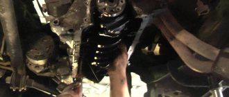
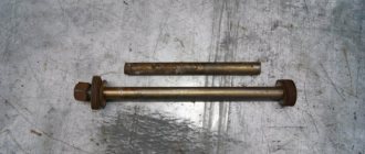
The cold has arrived on you too! I open the hood and there is oil all over the front cover of the engine. After looking at the whole thing a little, it turned out that oil was flying from under the crankshaft pulley. I did a little searching on the Internet about what and how, bought what I needed and went ahead with a friend to change the oil seal. We removed the hood to make it easier and started. In principle, everything went well, there were only minor problems with the pulley nut, in order to break it you had to put on a 38 key and rest it against the stabilizer and with short turns of the key, break it off with the starter, but there was one catch, a 38 key that I bought in the store “Samara” for 850 local money turned out to be made of such shitty metal that at the first pull of the starter it simply bent, I thought that was ALL! At this point the repair was completed, but then the father brought out a normal peasant wrench for 36-38 made of durable alloy, put it on, a friend turned it with the starter, the nut was easily unscrewed. photo of keys:
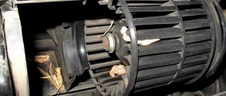
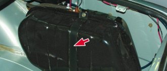
We replaced the oil seal, having previously lubricated it on the outside with sealant, cleaned the pulley and the seat for the oil seal and rinsed it with gasoline. We attached the pulley, tightened the nut, changed the oil in the engine, with an oil filter, by the way, like many people I probably don’t have a special one. a wrench for unscrewing the oil filter, some people twist it with a belt, but I hammer a screwdriver into it and unscrew it. It's not the same for everybody :-). Even after replacing the thermostat (I changed it in the fall), the car practically does not reach operating temperature, and now it’s generally so cold, well, just on the sly, we covered the radiator with cardboard and removed the fan from the pump pulley, now it’s better, the car warms up noticeably faster, and Even when the thermostat opens, the engine does not cool as much as before. Also, in the process, opening the radiator cap, a lot of air came out (I think it’s because of the heater radiator, which leaks a little, I already bought a new one, I’ll change it soon), lifting the front part of the car, they filled in antifreeze, about a liter o_O came in, I was shocked, after This made the stove heat better. While they were pouring antifreeze, we saw for the first time an unusual spiral inside, I personally, without attaching any importance to it, pulled it out. Here is a photo:
The importance of fine tuning
It must be taken into account that do-it-yourself adjustment of VAZ 2107 injector valves is available to all car enthusiasts, even in garage conditions, with a minimum set of tools. Often the operation is carried out on a hot engine, although it is preferable to do it “on a cold one”. The result will be more accurate readings.
It is important to know that adjusting the VAZ 2107 valves (injector) will require purchasing two types of probes: 0.15 mm for monitoring a cold engine and 0.20 mm for monitoring a hot engine.
Probes of different sizes are available for sale. It is preferable to use wide ones, as they are more comfortable to use, and they are often sold in pairs. As a result of proper setup and adjustment, the following results can be achieved:
- valve timing will work most accurately;
- the working cylinders will become fully filled with the air-fuel mixture;
- the mixture will burn as completely as possible;
- high-quality blowing of the empty cylinders will be ensured.
Correctly set valve clearance of the VAZ 2107 (injector) will result in cleaner operation of the internal combustion engine, possible knocks from the engine compartment will disappear, and the service life of the vehicle will significantly increase. This factor is a consequence of the lack of impact of the camshaft cam on the rocker (drive lever) or valve axis. Thus, these parts will be able to last much longer if the adjustment gaps are clearly ensured.
However, reducing clearances is considered more problematic for engine operation. With this position, the chance of the valve burning out increases, because it does not have time to install itself in the seat of the block head. Aggressive exhaust gas from the combustion chamber is directed through the resulting cracks. Its temperature during the explosion phase reaches 2000 C, which leads to burning of the edges of the exhaust valve. Valve seals are also negatively affected due to overheating, which is accompanied by increased oil consumption and contamination by combustion products.
The importance of adjustment is obvious for the performance and increase in the service life of the car. Control must be carried out depending on the degree of operation after 10-15 thousand kilometers.
When is it necessary to replace crankshaft bearings?
The HF engine experiences heavy loads. Just look at the vibration on the axis, which invariably occurs during the operation of the crankshaft. It is clear that the sliding bearings also suffer, because they take the blow first.
- Physical wear is the main reason when an engine liner needs to be replaced. The surfaces of parts wear out, backlash and vibration increase. Naturally, in such conditions the engine is in danger of knocking.
- Rotation is the second reason. More details about this are written below.
Thus, replacement of liners is required in several cases. Problems can be judged by various signs. For example, by the absence or presence of abrasive inside the lubricant. Also, a symptom of half-ring wear is low interference when installing the connecting rod cap.
Regarding factors that lead to wear or turning:
- dirty or too viscous lubricant - impurities and abrasive particles reduce the properties of the lubricant, and in general its cleanliness is one of the key rules of prevention;
- constant overload of the internal combustion engine - you cannot drive for a long time at high speeds, from time to time you need to pause, slowing down to 80-90 km/h;
- incorrect installation of half rings during a previous repair - as a rule, this occurs due to weak tension (insufficient clamping torque), so tightening must be carried out using a torque wrench.
Adjustment operations
The current valve adjustment scheme for the VAZ 2107 consists of the following combinations:
- sixth to eighth;
- fourth to seventh;
- first-third;
- fifth-second.
The entire countdown starts from the crankshaft sprocket. When the first pair is adjusted, we turn the crankshaft half a turn (180 degrees). This will allow you to move the necessary pistons to the uppermost position of one of the power strokes.
Next, we’ll look at how to adjust valves on a VAZ 2107 (injector). To do this, set the crankshaft to the starting position in accordance with the marks. They will allow you to move the fourth cylinder to top dead center. In this case, the distributor slider will be opposite the contact. This position allows you to adjust the following valves:
- on the 7th and 8th cams - exhaust and intake valves on the 4th cylinder;
- 4th cam – release on the 2nd;
- 6th cam – release on the 3rd.
Removal instructions
With the clutch disengaged, the crankshaft can be easily turned with a wrench.
To carry out the removal procedure, it is necessary to secure the shaft from turning.
There are special devices that are bolted to the pulley into the technological holes, preventing the shaft from turning. If there is no such device, then you need to install supports under the wheels and place the car on the fourth. You can also secure the crankshaft flywheel by inserting a long screwdriver or pry bar between its teeth.
Functions and design of the camshaft
The VAZ 2107 camshaft (injector and carburetor) synchronizes the operation of the intake and exhaust valves with the position of the pistons in the engine cylinders. It opens the exhaust valves to release exhaust gases and the intake valves to fill the combustion chambers with an air-fuel mixture. The “seven” uses an engine layout with an overhead camshaft. This reduces the cost of construction and makes the maintenance process easier. The VAZ 2107 camshaft is connected to the engine crankshaft via a chain driven by a sprocket. As the camshaft rotates, the cams located on it press on the rocker and open (close) the valves at the right moment. The camshaft bearing journals rotate in the bearings of the “bed” installed in the engine head. Lubricant from the oil pump is supplied to them through the oil channels, so the condition of the camshaft affects the pressure in the engine lubrication system.
Camshaft faults
The main reason for checking the condition of the VAZ 2107 camshaft is the appearance of a characteristic knocking sound in the head while the engine is running. There may be several reasons:
- wear of camshaft cams;
- wear of camshaft support bearings or bed journals;
- deformation of the part as a result of overheating;
- the appearance of a crack on the support of the part;
- camshaft fracture;
- lack of oil or low pressure in the engine lubrication system;
- clogged oil channels
- low quality oil.
If the camshaft wears out or cracks, the part must be replaced with a new one. But first, it’s worth localizing the problem by removing the camshaft and inspecting its condition.
How to replace bearings without removing the engine?
Many car owners think and write on forums that it is impossible to get to the liners without removing or removing them from the engine hood. However, such operations are carried out by repairmen on ships, where the size of the parts is enormous and too much force is required to remove the engine. And if the technique exists, it can be used for simple cars.
- Park the vehicle on a ramp to gain easy access to the engine. If there is protection installed on it, it should be removed and the lubricant drained.
- Remove the box, front cover and loosen the camshaft chain in advance. If you're not too lazy, it's better to remove it entirely so it doesn't interfere.
- Remove the starter and pan (if the beam does not interfere). If it interferes with operation, you will have to lift the motor and pull out the pan from under it.
- You now have access to the crankshaft. The easiest way is to replace the connecting rod bearings. The old bearings are pulled out after unscrewing the head screws; it’s easy to put new ones in place, just don’t forget to lubricate them well with the same engine oil that is in your engine.
- It is more difficult to replace the main bearings without removing the engine. You will need to lower the crankshaft by loosening its fastening. You don’t need to lower it much, ten, maximum fifteen centimeters.
- Now it will be easier to pull out the earbuds. But you will need an aluminum rivet, which must be inserted into the lubrication hole, so it will push the bearing out. The main thing is that the size of the rivet is suitable and does not scratch the crankshaft.
How to remove the camshaft of a VAZ 2107
Replacing the VAZ 2107 camshaft begins with its dismantling. To do this you need to do the following:
- place the car on a level surface;
- wait until the engine cools down;
- clean the engine head cover from dirt;
- remove the air filter, disconnect the cable, tip and rod of the throttle valve drive, remove
- fuel hose from the bracket (on a car with a carburetor engine);
- disconnect the air supply hose, vacuum hose and remove the fuel filter from the bracket (on a car with an injection engine);
- Using a 10mm wrench, unscrew the nuts securing the cylinder head cover;
- remove the washers from the cylinder head cover;
- release the wiring harness, crankcase exhaust and power steering hoses, and the headlight hydraulic adjustment tube from the bracket mounting;
- remove the cylinder head cover from the studs;
- remove the gasket;
- set the camshaft position so that it corresponds to the end of the compression stroke in the fourth cylinder;
- Use a chisel to bend the petal of the camshaft sprocket lock washer;
- engage first gear to prevent crankshaft rotation;
- Using a 17mm wrench, unscrew the camshaft sprocket mounting bolt;
- remove the bolt together with the lock washer;
- Using a 10mm wrench, unscrew the two nuts securing the chain tensioner;
- remove the tensioner;
- tie the chain to the camshaft sprocket with wire so that it does not jump off;
- remove the sprocket and chain, move it forward;
- Using a 13mm wrench, unscrew the nuts securing the camshaft bearing housing (this must be done evenly so that the housing does not “lead”);
- remove the bed along with the camshaft from the studs;
- use a 10 mm wrench to unscrew the two nuts securing the thrust flange;
- remove the flange from the groove in the front journal of the camshaft;
- pull the camshaft out of the bed (bearing housing).
Why is it necessary?
With the help of the crank mechanism of the engine, the reciprocating movement of the pistons of the engine cylinders turns into rotational motion and is transmitted through the transmission to the wheels of the car. The crankshaft is exactly what is needed to perform such a transformation. During operation, each of the pistons of a four-stroke engine is constantly in one of the strokes:
- inlet;
- compression;
- working stroke;
- release.
During the power stroke phase, the piston pushes the connecting rod associated with it, which, in turn, displaces the crankshaft. This is how rotation is realized. The piston next in the order of operation of the engine cylinders at this time compresses the combustible mixture and, after it is ignited, pushes its connecting rod, as a result of which the crankshaft rotates continuously.
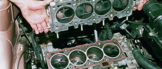
Flywheel
To the rear end of the crankshaft, when viewed from the location of the timing belts/chains, a flywheel is bolted through a flange - a massive cast-iron disk with a pressed-on ring gear (see photo). To ensure that the flywheel does not move and the balancing is not disturbed, there are centering pins or special bolts located asymmetrically. To prevent oil leaks, an additional seal (oil seal) is installed on the flywheel flange.
The flywheel accumulates the energy necessary to maintain uniform rotation in the intervals between ignitions of the combustible mixture in the cylinders and removes the pistons from their dead points (the extreme upper and lower positions of the piston in the cylinder). The flywheel ring gear is connected to the starter gear. When starting the engine, the flywheel is turned by the starter, giving the shaft an initial rotation. Finally, it is through the flywheel that rotational motion is transmitted to the components and assemblies of the transmission.
Usually, to monitor the correct setting of the valve timing, there are marks on the flywheel indicating the position of the first piston at top dead center.
Sock
In the front part of the crankshaft, called the “toe,” a pulley or gear is installed to drive the gas distribution mechanism, elements of the cooling system and other units (see photo). The sock is sealed with an annular cuff (oil seal). In addition, a dust deflector is installed on the outside of the sock in the engine cover, which prevents dirt from penetrating into the crankcase.
Manuals→VAZ→2107 (Zhiguli)
Cranking the engine
| To turn the crankshaft of a 4-cylinder engine manually, you need to place a 22 mm wrench on the alternator pulley nut. If the belt slips, you need to press on it. |
| The cylinder head cover nuts of the 5-cylinder engine must be tightened in the sequence shown, first with the following tightening torques of 5 N•m, then 10 N•m, and lastly 12 N•m. |
| TDC is found if o appears on the flywheel under the edge of the gearbox housing (arrow). |
To carry out some work, it is necessary to either bring the crankshaft to a certain position or rotate it.
| EXECUTION ORDER |
|
Setting cylinder 1 to the top dead center (TDC) position of ignition timing
In a four-stroke engine, the piston reaches top dead center (TDC) twice: the first time when igniting the incoming combustible mixture and the second time after the exhaust gases are ejected, finally beginning to re-absorb the fuel/air mixture. Usually, during various adjustment work, TDC of the ignition moment of the first cylinder is required.
| EXECUTION ORDER |
|
Removing the engine protective cover
The 6-cylinder engine is equipped with a protective cover that performs a noise-attenuating function. Removal:
| EXECUTION ORDER |
|
Removing the cylinder head cover
| EXECUTION ORDER |
|
The performance of all vehicle systems depends on the coordinated functioning of the elements among themselves. This applies to both new cars and outgoing “classic” models of the domestic automobile industry. Car owners of such vehicles are often interested in the procedure for adjusting the valves of the VAZ-2107. This is important to know, since when the crankshaft rotates, they alternately open/close according to a single algorithm.
Installation of camshaft VAZ 2107
The cylinder head camshaft is installed in the reverse order of removal. Before installing the part into the housing, it is necessary to lubricate the support journals with engine oil. When assembling, you should pay attention to two important points:
- correspondence of the marks on the camshaft and on the sprockets of its drive;
- tightening torque of the camshaft housing nuts.
First, you need to properly tighten the camshaft nuts. The nominal tightening torque of the nuts is 2.2 kgf•m. You cannot immediately tighten the fastening to such a torque. The VAZ 2107 camshaft is tightened in three to four stages so that the body is pressed evenly, without distortions. The nuts should be tightened from the center to the edges, in accordance with the “tightening chart” (see figure).
When the camshaft is installed, it is necessary to set its position relative to the crankshaft. There are marks on the camshaft bed, the front engine cover and the crankshaft and camshaft sprockets that should be followed. Even if the drive chain has been securely attached to the sprocket, when installing the camshaft, make sure that its position matches the position of the engine crankshaft. To correctly set the marks on the VAZ 2107 camshaft, you must perform the following steps:
- make sure that the mark on the crankshaft pulley is located opposite the long mark on the front engine cover (this corresponds to the top dead center of the fourth cylinder);
- install the sprocket on the camshaft and make sure that the mark on it matches the mark on the “bed”;
- put the chain on the sprockets without disturbing the position of the shafts;
- make sure that when the chain is tensioned, the marks match;
- tighten the camshaft sprocket bolt;
- turn the crankshaft two turns with the wrench;
- check the alignment of the marks on the camshaft and crankshaft;
- if necessary, change the position of the chain on the camshaft sprocket;
- Tighten the camshaft sprocket bolt and secure the lock washer.
After this, all that remains is to adjust the chain tension using the tensioner and complete the assembly by installing the cylinder head cover and other parts.
“>
Rotated liners: what does this mean and why do they rotate?
Rotating the engine bearings is a change in their position relative to the crankshaft journal or block. As mentioned above, this is caused by the colossal loads to which the parts are subjected. Shifting the bearings from their place immediately negatively affects the flow of oil. His pressure worsens, starvation begins and the power unit is destroyed. And all because the half rings are equipped with holes that must clearly coincide with the channels for the passage of lubricant.
The main reasons for cranking
There are several known reasons that cause elements to rotate:
- banal wear - the end parts of the sliding bearings wear out (support collars, stops, antennae), which are no longer able to hold the parts in one place;
- weak, incorrect fixation of the covers - the half-rings must be tightened with a certain torque specified in the passport data.
And of course, this arises due to a violation of the design operating conditions of the plain bearings themselves. In other words, due to a large and uneven load. This happens especially often with half rings with weak tension.
Rotating sliding parts can cause big troubles and therefore requires urgent intervention. The most dangerous is the shift of the main bearings. In this case, the power unit will definitely need an expensive overhaul.
It is noteworthy that when the connecting rod half ring rotates, it is simply updated. However, it is wrong to do so - because the resource of the mating connecting rod-pin pair in this case is reduced by almost 70%. Therefore, it is necessary to replace the connecting rod itself, in which a broken lock can often be found. And the most optimal method of repair is considered to be boring the crankshaft and replacing the complete liners, along with the connecting rods.