Features of connecting the alarm to the lock on the driver's door
Installing a central lock on the driver's door allows the owner to avoid the main reason for car theft: opening one of the passenger doors. That is why you should carefully study the car alarm connection points on the Priora in order to ensure maximum protection and ease of use of the vehicle.
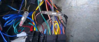
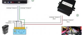
For the central locking to function, you will need to connect two wires to the driver's door. They should be triggered by a break in the brown wire when the lock is closed and, accordingly, the locking buttons are activated.
For the modern Lada Priora, the alarm connection points responsible for the normal operation of the autostart are also very important. You will need to connect a brown wire with a red streak to the dashboard connector. And the brown/white wire is connected to the generator. All this allows you to control the autostart procedure. The last connection point will be the brown/blue wire from the handbrake.
Upon completion of the full procedure for searching for points and connecting the corresponding wires to them, you need to visually evaluate the connections and check the operation of the alarm in action. Until the moment of complete reliability in the correct functioning, the Lada Priora alarm connection points must remain open.
This will allow you to immediately begin correcting them if any problems are detected. Once the goal is achieved, the plastic of the front panel and tunnels can be replaced.
Priora controller connector: how to properly connect the alarm system
Installation of the security system is quite simple and the primary connection points for the Priora alarm system are located on the controller connectors. First of all, connection is made to X1: 12V power supply to the red wire (numbers 2,3), turn signals are connected to the blue and blue with a black stripe wire (pins 14 and 15).
This connection stage is responsible for the normal functioning of the turn signals during alarm installation. And in addition, they will guarantee the correct operation of this part of the car’s electronics.
Next, work is done with connector X2, to which the wires from the ignition and hood will be supplied and connected. To connect the ignition, you will need to connect the orange wire (numbered 9) to the connector. A white wire with a black stripe (pin 17) is connected from the hood. This work is carried out for the following cases:
1. Preventing an attacker from trying to open the hood.
2. Prevent attempts to damage or remove the battery.
3. Normalization of autorun operation.
4. Correct functioning of the protection system.
The next step will be for Priora to connect the connection points on the last X3 connector. The work is quite simple and consists of connecting the wires leading to the limit switches. For the front doors, you will need to connect the brown wire (pin 7) for the passenger door and the blue/black wire (pin 6) for the driver's door to the connector.
Next, connect the yellow wire with a red stripe (pin from the trunk) and the gray wire with a red stripe (pin 1) for the rear doors.
Installation map for Starline A93 Can+Lin car alarm for Lada Priora Lux 2014-15 manual transmission
1. To access the ignition switch connector, remove the lower part of the steering shaft housing. To do this, you need to remove the plastic trim under the steering column, releasing the clamps, then remove the lower part of the casing (fastened with three self-tapping screws and two screws).
Steering shaft housing. General form
Plastic lining fasteners
Plastic cover removed
Self-tapping screws and screws for securing the steering shaft housing
The lower part of the steering shaft housing has been removed
2. To access the VSM unit, remove the left side trim of the central tunnel (fastened with one screw). Then remove the VSM unit (mounted with a bolt and nut).
Self-tapping screw for fastening the side trim
Side trim removed
Bolt and nut for fastening the VSM unit
VSM block removed
3. Install the antenna module with built-in shock and tilt sensor on the windshield, LED on the left pillar. Install the service button covertly in any convenient place.
Possible location for installing the antenna module
LED installation location
4. Install the siren under the hood (attach it to the nut) and the engine temperature sensor (using plastic ties). Route the wires into the passenger compartment through the standard seal on the left side of the engine shield.
Possible siren installation location
Siren installed
Engine temperature sensor installation location
The temperature sensor is fixed to the pipe using ties
Standard seal. View from the salon
5. Secure the StarLine A93 central car alarm unit to the right above the BCM unit.
An example of the location of the central car alarm unit
6. Connect the StarLine alarm ground at the bottom left under the VCM unit under the standard nut.
Ground connection
7. Connect the CAN bus and LIN bus StarLine in the harness of connector 3 of the BCM unit.
Conventional numbering of connectors on the VSM unit
CAN bus (yellow-red, pin 16 and gray, pin 15)
LIN bus (blue-white, pin
LIN bus connection
8. Connect the trunk limit switch in the harness of connector 3 of the BCM unit.
Trunk switch (yellow, pin 14)
Connect the hood end switch in the harness of connector 2 of the BCM unit.
Hood switch (white-black, pin 15)
Connecting the hood and trunk limit switch
9. In the harness of connector 2 on the BCM block, connect an alternative control of light signals (black and white wire of connector X3 of the Starline alarm system).
Light signal control (red, pin 5)
10. To bypass the standard immobilizer, remove the battery from the key and place the key in the StarLine BP-03 immobilizer bypass module. Then connect the bypass module to any wire of the standard antenna on the ignition switch.
Standard antenna wires (green and white)
11. In the ignition switch connector harness, connect the engine starting power circuits, power supply to the security system and the autostart power module.
Ignition (blue-black)
Starter (red)
Power + 12V (brown)
12. Program the security and service functions of Starline A93 (see installation instructions, section “Main menu for programming car alarm functions”, Table 1).
13. Program the vehicle starting parameters (see installation instructions, section “Main menu for programming car alarm functions”, table 2).
14. Adjust the sensitivity of the shock and tilt sensor (see the installation instructions, section “Connecting the transceiver (antenna module) and setting the shock and tilt sensor”). Factory sensitivity values: warning level of the shock sensor - 10, alarm level of the shock sensor - 5, tilt and movement sensor - 5. After setting, check the operation of the sensors, if necessary, repeat the setting procedure.
15. Check the operation of the Starline A93 car alarm. Reassemble the interior in the reverse order.
Car alarm connection points for Lada Priora
Block to the right of the brake pedal: hood switch (-) – white/black in the middle connector ignition (+) – orange in the middle connector trunk opening (-) – blue/red in the small connector door switch (-) – white/black in the small connector connector trunk limit switch (-) – yellow/red in a small connector
original siren – gray/black on the fuse block
To control the central locking , cut the brown wire in the driver's door and connect it according to the diagram:
How to set it up correctly
Control of the configured functions of the standard alarm is possible only after the process of its activation. The activation process itself is quite understandable and simple. It is described in detail in the technical documentation supplied with the car. However, it is much more reliable if this process is carried out directly in the salon by its employees.
If random failures occur due to a low battery, frost or other reasons, you can retrain the standard Priora alarm system yourself:
- charge the standard battery and check the presence of fuel in the tank of the car. All doors, including the trunk and hood, must be closed;
- insert the training key into the ignition lock cylinder;
- turn on for 6 seconds. Priora ignition;
- the standard immobilizer indicator lamp should blink at a frequency of 5 times/sec;
- after 6 seconds. The Lada ignition must be turned off and the training key must be removed;
- While the standard IMMO indication is on, insert the working key with the control key fob integrated into it;
- Set the ignition key to the on position. Then the standard alarm will emit 3 confirming signals. After waiting for the next 2 signals, the key with the control key fob integrated into it can be pulled out by turning off the ignition;
- if it is necessary to train a second standard key with a control key fob integrated into it, then the previous paragraph should be repeated for it;
- in 6 seconds, when the indication is flashing, you need to insert the training key and restart the ignition of the Lada Priora;
- The standard alarm will produce 3 clearly audible sounds. Then, within 6 seconds, it will make 2 more sounds;
- turn off the car ignition and wait for the last single signal. The IMMO indicator lamp should flash 2 times faster;
- at this time it is necessary to set the training key to the on position. for exactly 3 seconds. Wait for the buzzer to sound three times. The standard IMMO indicator lamp should stop flashing quickly;
- Do not turn on the ignition for 10 seconds;
- It is possible that the ECU will not allow the Lada Priora engine to start the first time. In this case, you should desynchronize it by turning on the ignition for 6 seconds.
What is an immobilizer for?
In addition to protecting the car from theft, the immobilizer performs a number of additional functions:
- the ability to control the delay for turning off the interior lighting;
- control of the rear fog lamp;
- checking the presence of the key in the ignition when opening the doors and giving a warning signal to the driver (one buzzer flashes in the instrument cluster);
- signaling that the external lighting is not turned off when the ignition is turned off (double buzzer signal).
The positive characteristics of using a standard immobilizer include:
- inability to start the car engine by turning the ignition lock cylinder or using a key without a chip;
- the ability to control the central locking using the standard key;
- when using a standard alarm system, it works in conjunction with the immobilizer, which provides additional protection;
- implementation of additional comfort functions;
- possibility of diagnosing the unit using a scanner.
The disadvantages of an immobilizer usually include the following points:
- The main disadvantage of the device is its unreliability. Quite often there are key failures, as a result of which the unit does not see the chip. This drawback forces owners to carry with them a second key from the set (with a red mark).
- The complexity of the training scheme and the risk of errors in the process.
- It is impossible to ensure automatic engine start without installing a bypass device or completely disabling the immobilizer.
- If the standard control unit is faulty, it is impossible to disable it yourself.
Central locking circuits
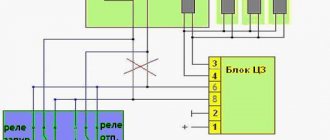
Locking and unlocking of the interior doors is organized through a two-step central locking chain. Three contacts of the electrical package control unit are connected to this circuit through a relay system. One power contact (12 V) and two contacts from which the control signal for the power window drives (front and rear) is removed. The two-step central locking circuit is connected through relay coils to the alarm module, and the door lock signals are removed from the alarm module.
Completion of educational program about Lada Priora
After reading, many will probably be overcome by a feeling of powerlessness. Indeed, all the described actions cannot be completed if you do not have experience in repairing Russian Zhiguli cars, as well as the skills of a specialist in electronic systems. The bulk of car owners are still ordinary people who use the vehicle simply as a household appliance and nothing more.
All thoughts are more likely to suit creative people - those who not only drive a Zhiguli, but always strive to improve. For this category of readers, all that remains is to add: all the necessary diagrams of connectors, connections, wiring are available in sufficient quantities on the network. So, you can pick up the tool and start installing the latest model of alarm system on the Priora, if one has not yet been installed to this day.
Signs of a faulty factory security system
- the car does not start;
- the electronic control unit does not respond in any way to pressing the key fob;
- the system does not work when hitting the surface of the body;
- constantly activated for no apparent reason;
- the doors are locked after pressing the open button.
Malfunctions are often associated with the design of the standard security system. Owners of domestic vehicles note that after several years of operation, the starter does not activate when trying to start the engine, or turns off after a few revolutions.
If one of the problems occurs, turn off the device, then contact the installers to diagnose and determine the cause of the problem. Before contacting the service center, test the system yourself, following the sequence of measures.
Setting up autostart - Starline alarm
First you need to understand that there are two types of engine starting - remote or automatic. Remote start is needed, for example, to warm up the car before driving. Automatic engine starting involves periodically starting the engine, for example at night, to maintain the desired temperature. Autostart can be configured so that the car starts at certain intervals or when the temperature drops below a preset value.
Conditions for autorun
Remote engine starting can only be performed if the following conditions are met:
- The gear knob is located in neutral (gears are off)
- Ignition off
- The hood, trunk and all doors are tightly closed
- Parking brake engaged (handbrake)
If any of these conditions are not met, you will not be able to start the engine remotely.
Preparing the car
In order to put the car in security mode with the Starline autostart function enabled, you need to take the following steps:
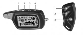
1. Stop, do not turn off the ignition. The engine must be running. 2. Turn off the gear, the shift lever should be in neutral position. 3. Put the car in “handbrake” - turn on the parking brake 4. Press button 1 on the key fob and hold it for 3 seconds. You will hear a melodic sound signal. You have 30 seconds to complete the following steps. 5. Turn the key to turn off the ignition and remove the key from the lock. The engine will not stall, but will continue to run. 6. Get out of the car and make sure that all doors, trunk and hood are closed.
After you close the last open door, trunk or hood, the alarm will automatically turn off the engine and lock all doors - the security mode is turned on.
Only after successfully completing these steps will the autostart function be possible and the engine can be started remotely.
Remote start
If you have correctly prepared the car for autostart (closed the door with the engine running and the alarm turned off), then you can start the engine using the key fob in any of two ways:
1. Press button 1 and hold it for 3 seconds. or 2. Select the “START” icon and press button 2.
After this, the alarm will make its first attempt to start the engine. If the engine does not start, a second attempt will be made, and the starter operating time will increase by 0.2 seconds each time. There will be 4 such attempts in total. If the engine does not start any of the four times, you will hear 4 beeps from the key fob.
If the engine starts successfully, the corresponding icon will be displayed (it varies on different Starline models, usually the exhaust gas icon), the car will blink its dimensions 3 times and you will hear 3 siren signals.
The car will warm up for a certain period of time, which is set in the settings. Options: 5, 10, 15, 20 minutes. One minute before the end of the set time, the inscription “r01” will appear on the key fob display. When the time is up, the alarm will turn off the engine, and the exhaust gas icon will disappear on the key fob and the inscription “r00” will appear.
Autostart based on temperature
In winter, many people need to warm up their car at night so that there are no problems with starting in the morning. When you enable autostart based on temperature, you can set the ambient temperature value at which the engine will start. The following temperature values can be programmed: -5, -10, -20, -30.
To enable the temperature start function, select the icon with a thermometer and the inscription “START”, and press button 2 on the key fob. At the same time, you will hear a melody sound and the value of the set temperature threshold should be displayed.
To turn off automatic start based on temperature, select the thermometer icon again and press button 2 on the key fob.
If, while the engine is warming up, you need to get into the car (to start driving or just take something from the cabin), press button 1 on the key fob - the locks will unlock. Within 30 seconds, insert the key into the ignition and turn it to turn the ignition on. If you do not have time to do this, the locks will be locked again and the security mode will turn on. In order to completely exit the autostart mode, lower the handbrake - the dimensions will blink once and a melody sound will be heard - you can drive.
Ghostex › Blog › Connecting the signaling system to the central locking system on Priora-2/Grant/Kalina-2
This topic is dedicated to those whose central locking (CL) malfunctions due to the signaling, that is, every time or after the tenth attempt they open/close the locks.
This problem appears on the latest Priors, Grant and Kalina-2 Lux, if such a block is installed on the driver's door.
And on such cars there is such a “central body electronics unit” (CBEC), which is glitchy with locks.
There is a simple solution to this central locking problem, but it requires reconnecting the signaling, the presence of direct hands, a head and a soldering iron.
Let's get started:
1. We disassemble the door and remove the block of buttons in the driver's door and disassemble it, it is not difficult, the bottom cover is fixed with latches, remove it and remove the board. Here she is:
2. We need a central locking button. This one:
We take 2 wires and solder them to it.
And we put the block back together and make a hole in the body for the wires.
3. Next, we find 2 wires laid separately in the door, they come from the signaling and connect to the brown
wire in the gap.
This brown
wire goes from the lock to the button block.
And so, we find the connection point and disconnect the signal wires, and restore the brown wire.
And we connect these two wires from the signaling to the two wires coming out of the button block, and it makes absolutely no difference which one goes to which one.
4. Next, we look for the signaling itself and take it out. The central locking is the same on all signaling systems, only the colors of the wires are of course different, then I will tell you using the example of Starline, KGB and Tomahawk signaling (with start or just with feedback), since they have almost the same wires colors and I feel more comfortable with an example.
We will work with a small central locking connector with 6 wires, inserted here:
And on other alarms, find 6 central locking wires using the diagram in the instructions.
A little about the central lock contacts:
out of these six wires we have: 2 - normally closed contacts, 2 - normally open and 2 common contacts - these are outputs to the central locking system or the drive itself.
These signals have: - blue and green common outputs to the central locking; - blue-black and green-black normally closed contacts; - black-red or blue-red and green-red (or also blue-white and green-white) normally open contacts.
5. This is the diagram you used to connect the central locking system to.
Now we have already hooked up the brown wire and remade the wires for the button.
From this diagram you can see that the common outputs (blue and green) are connected into one wire and go to the door buttons; we leave them unchanged.
Next, we need normally open contacts on the signal (black-red or blue-red and green-red), one of them is connected to ground, disconnect it from ground and connect the normally open contacts together in any way, since they can be greatly shortened by unnecessary. And then we connect these two combined wires (black-red or blue-red and green-red) with the second wire going into the door, in this case green-black (this is a normally closed contact on the locking relay), only by biting it off the signaling connector .
This is how it should turn out.
Thus, our signaling will, as it were, press the central locking door button.
That's all, put on all the connectors and you can try. I hope it will be useful to someone, good luck!
Attention, there is a drawback to this alteration!
After the modification, the signaling system will seem to press the central locking button, when arming the doors will close, when disarming they will open, but the downside is that if you arm the door, they will close, and if you arm it again, the doors will open and the car will exit. security, and the doors are open, so make sure to arm it once, and it will work perfectly.
Now I’ll think about adjusting this, and I’ll post a correction in the future.
Source
Let's connect further
The connection in the driver's door is made using two wires. If you use remote start, then the following must be done. First, open the ignition switch connector. +12 Volts should be connected here. A brown wire is used for these purposes. Also, don’t forget about the ignition and starter.
In the first case, a blue-black conductor is used, and in the second, a red one.
The dashboard also has its own connector. Here you should perform certain manipulations related to the connection. The tachometer is installed on a brown-red conductor. The generator will be brown and white, and the handbrake will be brown and blue. Here you should not forget about the additional inclusion of a diode in the circuit.
Essentially, this is all you need to know when connecting alarm points on a domestic Lada Priora car. If everything is done in accordance with the diagram, then the alarm will work just perfectly.
There are common mistakes, for example, some install wires on the wrong pin. In this case, you can come to the conclusion that as a result of starting the alarm will simply burn out
You should always pay attention to the polarity of the supply voltage. Otherwise, you may be very disappointed in your own work.
So, we talked about what alarm connection points exist on our favorite car - Lada Priora. As you can see, all the work comes down to the elementary installation of limit switches and wires into the corresponding pins. The alarm connection points on the Priora can be called primitive. Some other car brands have much more bells and whistles in this regard.
Alarm on a Priora is a serious issue; everyone is afraid for their car, trying to protect it to the maximum. The Priora is equipped with an alarm system from the factory - an immobilizer (immobilizer). On a Lada Priora car, it allows you to partially protect the car from theft. The immobilizer on the Prior is a factory anti-theft device combined with the car's electrical package, which is located under the center console. Owners immediately try to disable the immobilizer on their Priora, because they consider it archaic and prefer to install a more advanced alarm system on the car instead of the standard anti-theft one. Installing an alarm on a Priora will cost approximately 10,000 -17,000 rubles.
Disabling the immobilizer on a Priora is not easy. The engine is started by an electronic engine control system, which also blocks its operation when the immobilizer is turned on. And already in the electronic control unit of the car, in the place where the EEPROM circuits are stored, the process of data exchange with the immobilizer takes place, and at the ECU level there is a ban or permission to start the engine. You can turn off the alarm on a Priora yourself, but this requires knowledge of electronics and special tools.
Installation process
First of all, let's consider what you will need when installing a car alarm:
- signaling;
- driver's door activator;
- screwdriver;
- soldering iron, solder, rosin;
- insulating tape;
- additional protective diode.
The first step is to remove the steering shaft trim, then unscrew the 2 self-tapping screws securing the instrument panel trim, and just below that there is another self-tapping screw and a nut. Next, you need to install an LED in the left windshield pillar, a shock sensor on the cross beam, and install a service button in any convenient place. The antenna is mounted on the windshield.
The process of connecting the 18-pin connector of the alarm unit (required wires for connection):
- black wire - ground;
- a short loop of black wire - if the automatic transmission is left in a loop, if it is a manual transmission, it is cut;
- green-black and green-yellow wires are connected to the turn signal lamps;
- gray wire - siren control output;
- blue-black wire - door limit switches;
- the orange-gray wire is connected to the hood end switch, it also needs to be connected to the engine temperature sensor;
- the orange-white wire must be connected to the trunk end;
- The pink wire is connected to the minus of the “immobilizer bypass”;
- gray-black wire - control by generator signal during automatic start;
- orange-violet wire - connects to the handbrake.
Notes on implementation of schemes
Let us immediately note: if there are no window lifters, the second diagram will not contain parts K2/K3. Then you only need to cut one wire. Sometimes only the rear windows are missing. This means that relay K3 is excluded. And the diodes connected in parallel with the winding can be absolutely anything.
Diode, zener diode - everything will do
Now we list the requirements for an element called “relay”:
- Operation voltage – 12 Volts;
- Switching current – 10 A or higher;
- The current consumed by all relay windings should not exceed the value specified in the instructions for the signaling. Usually it is 200-300 mA.
It is the last requirement that is often violated.
Diode with relay, ready module
In order for “scheme 2” to work, it is necessary not only to assemble it, but also to program the main unit: you need to enable the “2-step unlocking” option. And be that as it may, control impulses cannot be made too long. Use values of 0.7-1.1 seconds.
Power cables (cord X1-6) can only be connected using twists.
The cross-sectional area of the wire must be sufficient to withstand a current of “10 Amps” (this does not apply to signal circuits). A fuse protecting the power circuits must be installed. And of course, before installation, remove the negative terminal of the battery.
The lock and alarm can be connected directly
The alarm only works when the ignition is on
The phrase “connecting the alarm to the central locking” often means this: there is a central locking control unit in the car, and it continues to work, and the alarm is connected to it. But in some cases it is easier to get rid of the standard control unit for the central locking system, and then only the signaling system will control the actuators. We will now consider the case when the lock and alarm are connected directly. For example, here is a method for connecting the Mongoose alarm system.
Types and types of actuators
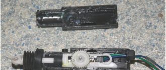
The actuator is the actuator of the lock drive. Any such mechanism is enclosed in a plastic case, and an electric motor is installed inside it. The engine is equipped with two contacts, the wires from which are led out.
Door lock actuator (two wire)
The two power wires are sometimes supplemented by two or three signal cords, which are connected to microswitches. A module equipped with such options is usually implemented according to the following scheme:
Driver's door lock actuator
There may be 4-5 signal wires, but the point here is different: these cables will be shorted when the drive is moved to one of the fixed positions. And there are usually two of these positions: completely open, locked.
It is important to understand the logic of the microphone’s operation: until the rod is fully retracted, the toggle switch remains in the “open” position. And vice versa: the toggle switch will take a different position if the rod is pressed out to the end
It’s easier to imagine that the switching occurs after the rod stops. There is nothing more to add here.
Connection of a microphone built into the actuator is provided only in some signal models. And for all doors except the driver's, two-wire drives (without microswitches) are suitable.
Standard set for sedan
In any case, it is better to buy one 5-wire actuator. By the way, the resistance of each motor is 5 Ohms (calculate the total current). Happy shopping!
Connecting and setting up an alarm system
The main signaling unit must contain two relays. One of them closes when the locks need to be opened, the second is intended for unlocking. The contacts close as follows: for 0.8 s. the winding is connected to power, then disconnected. And during this period the actuators operate. For this case, there is a basic scheme.
Schematic for Mongoose 3D
We pay attention to how the microswitch should behave:
- When “locked” completely, there is no ground on the wire;
- In all other cases, the cord must be connected to ground.
We will talk about an actuator equipped with 5 wires. The connection is implemented as follows: you need to call the signal wires, and then connect one cord to ground. The second one remains free, and the common contact is connected to the wire that goes to the signaling (it is “gray” in the diagram).
Microswitch actuator, device
You can not call anything, but simply disassemble the actuator. If you don't mind, of course.
Power wires are connected by twisting, and the connection points are insulated. The actuator motors are switched “in parallel”. And whoever decides to exclude the fuse, let him blame himself. By the way, it is better to entrust the installation of power cables to an experienced electrician.
Main unit programming, testing
We connected everything correctly, but forgot to program the alarm. Having opened the instructions, we see that the gray cable goes to the programmable input, and by default it operates in the “limit switch” mode. Obviously, the input needs to be switched to another mode, and this option is discussed in the instructions:
Screenshot of Mongoose 3D manual
We need the option “2-3”, which we will translate into the value “2”. Let the duration of the control pulse (option “1-2”) remain at the value “0.6”.
Having completed everything as stated above, you will be able to observe the following effect: the signaling system performs the functions of a central locking system. By pressing the driver's door pawl, we lock all the locks. Which is exactly what we needed. And without reprogramming the main unit, it’s unlikely that anything would have worked.
Applying supply voltage for 2 seconds or more disables the actuators.
It is important to remember: the duration of control pulses cannot be made too long. It's difficult to understand why the developers set the value to 4 seconds
And although it is not used by default, there is a possibility of making a programming mistake. Be careful!
How to activate the immobilizer
- To activate the immobilizer on a Priora, you will need a training key. It is almost 2 times smaller in size than the real one, and is used only during “training”. To work with it, you should adhere to the following algorithm of actions:
- Close all door locks;
- Insert the training key, turn it and hold it in the final position for at least 5-6 seconds, and then turn it back. During these 5-6 seconds, the indicator light on the dashboard should blink continuously. If it goes out ahead of time, it means something was done wrong.
- Remove the training key from the ignition switch and insert the working key, start the ignition system. All this needs to be done while the light on the dashboard is flashing. If everything was done correctly, three beeps will sound first, followed by two more after a pause. If this does not happen, then the immobilizer is faulty.
If the light on the dashboard is still blinking, turn the key back.
Features using a specific example
Autostart settings for Sherkhan 5 every 2 hours or when the temperature in the cabin drops to – 15 °C, with the cabin warming up for 25 minutes, perform the following manipulations:
Simultaneously activate buttons I and II, then press VI twelve times, and finally hold down button III (functions 1-12 are adjusted taking into account the time value of 25 minutes); Activators I and II are pressed synchronously, button No. VI is clicked 13 times (alarm functions No. 1-13 are set to a time value of 2 hours; Press I+II and VI simultaneously - 21 touches (function 1-21 is set to temperature - 15 °C).
Using this principle, you can set autorun to different time limits and temperature conditions. It is worth remembering that an error at any stage of the settings will require starting the entire process all over again.
https://youtube.com/watch?v=MT9bKo0pN3M
Two schemes (simple and complex)
First of all, before connecting the alarm, you need to study the instructions included with it. The main unit always has relays installed: one of them closes when the locks are locked, the second acts on opening. The connector to which the relay contacts are connected usually has 6 pins. There is nothing complicated here.
From the instructions for the signal
In the first case, we will use only this connector. The second circuit uses another contact, called “signal output for 2-step lock opening”. Find it on the main unit.
We connect the alarm in a simple way
A push-button module is installed in the driver's door of the Lada Priora. The door trim must be removed and the connector for this module must be found:
Button block, left door
We will need a brown cord from the connector. It is a signal, and the alarm relay is connected to its break:
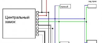
Diagram 1, simple connection
Two wires connected to each side of the cut cord will have to be pulled to the main unit. The common contacts of the relay are connected to one of the wires.
All wiring in the considered circuit is signal, but this does not mean that the connection points need not be isolated. Wires should not touch metal parts of the car. If contact occurs, it is necessary to use additional protection: electrical tape, heat-resistant tube, etc.
The best option for connecting to the central locking system
Having made the connection, as discussed above, you can notice the following: all locks are activated from the key fob for closing, and only one, the driver’s, is activated for unlocking. This defect can be eliminated 100%, which will require 2 or 3 additional relays. First, let's look at where the connection points are:
BUS block, Lada Priora
The block that is visible in the photo is designated BUS-2170. It is equipped with three connectors, but we need one (three-row).
Find three wires in connector X1:
- Sixth (red-black). The cord goes to the actuators and is the power one.
- Thirteenth (green-black). Front right power window control cable.
- Eleventh. Same as “13”, but for the rear window lifter.
How to connect an alarm system to the central locking of a Priora Lux? Three wires are broken (all indicated), and the cables from the break points are pulled to the signaling unit. If you don't have rear power windows, the last cord will be missing. And if there are no power windows at all, cables 3 and 2 do not break (they are still missing).
The BUS unit will be installed behind the dashboard, near the gas pedal. To remove it, dismantle the side panels and unscrew two 10mm nuts. These nuts secure the block on both sides. From each of the break points, a cable is laid to the signaling system, which also applies to the brown cord coming from the door block:
Scheme 2, ideal option
Here we use additional relays (K1-K3), a 15 Ampere fuse and nothing more.
If the central locking from the key fob does not work: troubleshooting sequence
The alarm is blocking the fuel pump, how to turn it off
p, blockquote 24,1,0,0,0 —>
Any repair or troubleshooting in a car must begin with checking the fuses that serve a specific system. There are three of them in the diagram below. Usually it can be more. You need to find their location using the car's instruction manual or searching on the Internet.
p, blockquote 25,0,0,0,0 —>
Video - if the central locking does not work from the alarm, then first check the fuses:
p, blockquote 26,0,0,0,0 —>
p, blockquote 27,0,0,0,0 —>
If all fuses are in good working order, proceed to determining the location of the malfunction based on its characteristic symptoms.
p, blockquote 28,0,0,0,0 —>
Central locking does not close the doors
There are several options for central locking:
p, blockquote 29,0,0,0,0 —>
does not respond to the key fob signal at all, in this case it is necessary to check, or better yet, immediately change the key fob battery;
does not close the door even with the lock key;
closes and immediately opens the doors.
The last option is associated with loose closure of windows or doors. It is necessary to try to press each door sequentially, supporting it with your whole body, and at the moment of pressing, try to close the central locking.
p, blockquote 30,0,0,0,0 —>
Perhaps a foreign object has gotten into the closing area of a door; it needs to be checked. You should also check the pressure of the glass so that it fits tightly into the upper grooves.
p, blockquote 31,0,0,0,0 —>
If the central lock does not respond to the key fob and key, the wires may have broken in the area of the corrugation entering the door. If you have experience repairing electrical wiring, you can find the faulty wire and connect it.
p, blockquote 32,0,0,0,0 —>
The central locking system does not open the doors, but at the same time closes them
One option is to shift the door hanger. The lock is locked with a door latch. This type of malfunction often occurs in the trunk doors. You have to press them manually to wedge the movement of the lock drive. When you try to open the door, you should hear a click from the drive. In some cars it is almost inaudible; you have to put your ear to the door.
p, blockquote 33,0,0,0,0 —>
Central locking only closes the driver's door
Here, most likely, the malfunction is a breakdown in communication from the driver's door control unit to the central unit or other doors. You should remove the corrugated hose from the wiring transition from the driver's door to the car interior - there will be a break there.
p, blockquote 34,0,0,0,0 —> adsp-pro-2 —>
In some car models, there is a connecting connector at the junction of the wiring into the car interior; you can check its contacts. It is also necessary to examine the electrical wiring under the door trim and all connectors.
p, blockquote 35,0,0,0,0 —>
One of the doors does not open
Possible malfunctions: damage to the electrical wiring in the corrugation or on the way to it in the cabin, malfunction of the lock drive.
p, blockquote 36,0,0,1,0 —>
Video - the central locking of the driver's door on a Skoda Fabia does not work:
p, blockquote 37,0,0,0,0 —>
p, blockquote 38,0,0,0,0 —>
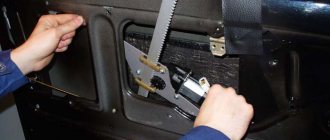
The lock drive is easy to replace and is inexpensive. During replacement, the main thing is not to damage the levers, rods and plastic tips.
p, blockquote 39,0,0,0,0 —>
p, blockquote 40,0,0,0,0 —>
If you replace the central locking drive yourself, to be sure, it is better to find a mechanical diagram on the Internet, reference books, or instruction manual so that you do not forget to install any part.
p, blockquote 41,0,0,0,0 —>
p, blockquote 42,0,0,0,0 —>
Purpose:
The remote control is designed for remote control of locking and unlocking of car doors, turning on and off super-locking doors, turning on and off the alarm system, raising the windows, controlling the locking of the tailgate (trunk lid), and also as a coded electronic key for the APS-6 immobilizer
The remote control is mounted on the blade of the ignition switch key type 1118-3704010 and is designed to operate:
- with electrical package control unit 1118-6512010
- with driver's door module 1118-3763080, 2170-3763080-00/10
2) via transponder channel:
- with immobilizer control unit APS-6 2123-3840010-ХХ;
- with immobilizer control unit APS-6.1 1118-3840010-ХХ;
- with electrical package controller-2170-3763040.
Important functions of the Starline A93 alarm system
What areas does Starline A93 protect:
- All opening parts: doors, hood, trunk, parking brake, brake pedal, control, through limit switches
- Body, vibration response, two-level shock sensor, tilt sensor
- Ignition, control via input to the ignition circuit
- Engine - blocking relay, code relay StarLine R3 (optional)
- Interior space - additional sensor (optional)
Anti-theft device options:
- Security mode with sound and light alarms
- Providing alarm alerts to a key fob with an LCD display
- Silent activation/deactivation of security mode
- Silent security mode
- Security mode with engine running
- Turning security on/off without using a key fob
- Automatic return to security mode in case of accidental shutdown
- Automatic arming
- Immobilizer mode
- Anti-robbery mode
- Panic mode
- Programmable personal code for emergency disarming of the security mode
- Engine blocking and its preservation when dismantling the car alarm
- Programmable 2-step engine lock release
Self-diagnosis and fault detection functions:
- Indication of trigger causes for 11 zones
- Alarm of a faulty zone when arming
- Automatic monitoring of the status of security sensors with disabling faulty ones and reporting their malfunction
- Indication of the fact of activation by sound signals
- Indication of car alarm by LED and on the key fob display
- LED indication of limit switch serviceability
What service functions does this model have:
- Activating sensors before turning off the interior lights and bypassing the door area
- Disabling security, adjusting the volume of signals
- Remote disabling of the shock and tilt sensor in security mode
- Remote control of the central locking system (central locking)
- Central locking control from the ignition switch
- Two-step lock opening
- Two-pulse closing of door locks
- Six channels for controlling additional equipment
- Car battery voltage monitoring
- Determining the temperature inside and outside the car
- Search from car
- Light alarm for open doors
- Turbo timer mode
- Remote programming of functions and key fobs
- Service mode
- Car interior light control
- Call from car
- Insurance against accidental pressing of key fob buttons
- Registering new key fobs and deleting lost ones from the system memory
- Setting the time, alarm clock, timer
- Main key fob charging control
- Possibility of working together with GSM modules StarLine M20, M30 and StarLine M21, M31 (car alarm control and monitoring its status via GSM channel
- Remote and automatic start, extension, engine stop
- Remote engine start in cars with a start-stop button
- Works with any engine: gasoline/diesel
- Transmission choice: manual or automatic
- Monitoring engine operation using signals from a tachometer, generator or mains voltage
- Protection against starter overexposure when starting the engine
- Understanding the remaining engine operating time on the key fob
Eventually
The immobilizer is a truly outdated device in principle, and it is disabled or bypassed. In return, you can install a reliable alarm system and “secrets”, which are more likely to protect the car from intruders, and not from its own owner. Modern anti-theft systems, of course, are “hackable with a glance,” but they give the owner an accurate idea that everything is fine with the car.
Probably every car owner has thought about protecting their vehicle, and the most common protection option is an alarm system. A car alarm is an electronic device that is installed in a vehicle and is designed to protect it. The alarm emits a sound and light signal, thereby notifying the vehicle owner and everyone around about unauthorized intrusion into the vehicle interior. The installation of an alarm requires initial preparation, namely, the owner must find the alarm connection points. This is exactly what we will talk about today.
So, in this article you can find answers to these fairly common questions:
- Standard car alarm Priora;
- Malfunctions of standard alarm systems and methods for solving them;
- Alarm connection points for a Priora car;
- Installing an alarm system on a Priora car.
