Signal Connection Diagram Through Relay
Due to the fact that Volgov signals consume a larger current of 14 A than the standard 5 A, this fuse will burn out when the fan and Volgov signal operate simultaneously, and the corresponding tracks on the printed circuit board in the fuse block may also be damaged. I picked out the connectors from the old wiring from the Zhiguli and clamped them onto a new speaker cable. You can buy Relay Finder at .
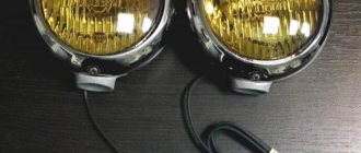
Connect one contact of the multimeter to the minus of the circuit, and connect the second to ground. Fortunately, the choice is huge, from simple inexpensive two-tone signals with good sound to compressor signals. Four-pin relay, connection. This is where many car owners think about replacing the standard sound signal with an alternative one. It will also make the signals trigger clearly. That's right, to relieve the load on the car wiring that comes from the steering wheel. After all, the volume and sound of standard signals, both on most domestic cars and on many foreign cars, leave much to be desired. If we want to add credibility to our signal, we simply need to replace it with something more serious. In case of such a problem, the operation of the horn can be restored, since it is not damaged. I bought these signals produced by LETZ without brackets: I decided to install them behind the radiator grille, since under the hood the sound would still be a little muffled. To do this you need to use th contact. Let's consider connecting fog lights. Installing a signal (horn) via a relay on a Toyota CROWN S171
Do-it-yourself signal diagnostics and repair
How to check and repair the horn yourself? For diagnostics, you will need a tester (preferably a digital multimeter, but if you don’t have one, you can use a regular one), crimping pliers, pliers, and a utility knife. Prepare spare wiring and a service manual for the machine.
Checking with repairs is performed as follows:
- The functionality of the fuse and relay is checked; you need to find the mounting block. A more precise diagram is indicated in the technical documentation, but usually the safety device is located in the power supply unit; it can be installed in the dashboard. Once you have located the block, examine the diagram on the back of the block cover to find the fuse. Dismantle the device that is responsible for the operation of the horn and carefully inspect it - if there is an open circuit, this indicates that the fuse is not working.
- But if the device is intact, this does not mean that it is functional. You need to diagnose it using a tester. Set the multimeter to the resistance measurement mode with sound (if we are talking about a digital tester and it has such a function). If you have an analog multimeter, before diagnosing you will need to calibrate the tester; to do this, short-circuit its probes with each other and move the regulator to zero. Then press the tester probes against the contacts of the safety device. If the part is working, then the multimeter will show 0 Ohm, but if not, then if there is no change on the display, we can conclude that the resistance is too high. This indicates a broken fuse and the device needs to be replaced.
- After this, if the fuse is working, you need to find the relay block, which is located either in the engine compartment or in the interior of the car - use the service book to search. Typically the relays are located in the same fuse box. The easiest way to check the operation of the relay is to swap the devices with other similar parts. In most cases, relays are interchangeable, so if after replacing the device the horn starts working, then you can understand that the reason was in the relay.
- You should also check the steering horn switch; a tester is also used for this. If there is no power supplied to it, then of course the button will not be able to respond to pressing.
- Next, diagnose the functionality of the relay switch. To do this, you will need to dismantle the relay and set the resistance measurement mode on the multimeter. One contact from the tester should be brought to the relay switch connector, and the second is connected to the negative terminal of the battery. With this connection, the assistant must press the beep button. As a result, numerical values should appear on the display. If the message Out of Limits appears on the screen, this indicates that the switch is not in working condition, and accordingly, it needs to be changed.
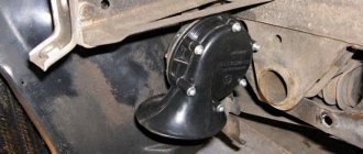
- It would be a good idea to check the horn itself. As a rule, the horn device is located behind the engine radiator grille, directly in front of the main radiator device. Having found the mechanism, you need to determine which of the conclusions is positive and which is negative. Please refer to the technical manual to determine this accurately. Once you know this, connect the horn directly to the car's battery to check its operation. The positive contact is connected to the plus, the negative, respectively, to the minus. When the negative contact is connected, the horn should start working, but if the connection does not produce results, then the device is faulty.
- The next step will be to diagnose the circuit. If you have any suspicions about the health of the electrical circuit, you need to check the grounding of the circuit, as well as the voltage and current values. Determine the mass to accurately identify grounding; for diagnostics, set the tester to measure resistance in Ohms. Connect one contact of the multimeter to the minus of the circuit, and connect the second to ground. As a result, numbers should be shown on the tester screen - if they are present, the wiring is intact. At this stage, you need to check the condition of the contacts. As practice shows, often the cause of failure lies in their oxidation, so it makes sense to clean the contacts.
FakeHeader
That's it, the mechanical part is over, let's move on to the electrical part. As a rule, the horn device is located behind the engine radiator grille, directly in front of the main radiator device. As practice shows, often the cause of failure lies in their oxidation, so it makes sense to clean the contacts. Already crimped wires with terminals are sold in stores.
Using this circuit, you can connect almost any powerful device and control it with a small, beautiful key. I planned to do it from the front, instead of the standard one, but I couldn’t unscrew the grille mounting bolts. Connecting an air signal If you need to connect not an electric, but an air sound signal, the connection procedure will be almost the same as described above.
To do this, you will need to dismantle the relay and set the resistance measurement mode on the multimeter. The difference is that the wire from the relay does not go to the sound signal itself, but to the compressor engine, which supplies air to the signal. We mark the corner at the installation location, saw it off, and drill holes for attaching signals from the Volga.
This petal may burst over time; sometimes the cause should be sought in the jamming of the pressure rack. So we bring to your attention a diagram for connecting an audio signal through a relay. It is universal for most cars, with the exception of those cases when audio signals are used that receive mass through the body, for example Volgov's, for which the diagram is slightly different.
That's it, the mechanical part is over, let's move on to the electrical part. (easy and fast) Volgov Signals on VAZ 2107
Repair of sound signals on VAZ cars of various modifications
Sound signals, as such, are not among the most complex elements of a car, however, traffic safety and the ability to avoid emergency situations largely depend on their good condition. Be that as it may, even with all its simplicity of design, the sound signal (including on various modifications of the VAZ) may stop working and if such an unpleasant situation arises, you can most often cope with the problem on your own, it is enough to have the appropriate diagram at hand and follow a few simple recommendations.
In general, the connection diagrams for the sound signal on the VAZ “classic” series and on subsequent front-wheel drive models are quite similar and the main differences relate to the relay markings, as well as the location of the fuse. Among other things, on the earliest versions of the VAZ (2101, 2102, 2103 and a number of modifications 2106), the electrical circuit of the sound signal or the presence of a unloading relay is not provided at all.
How to connect via relay. Scheme
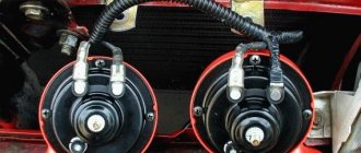
At home, we will first prepare the mounting of signals from the Volga based on a steel angle purchased at any building materials store. For example, I recently gave a car I had made to a man, and over time his signal stopped working.
I connected the power to the standard signal circuit, there is a 16A fuse there, in addition to the signal from this fuse, the rear brake lights and interior lamps are powered, all of which are LEDs. Well, somehow it’s not solid. Take it and connect it. Everything turned out perfect. In this case, the contacts close, which again leads to the passage of current through the winding. The wires to the fog lights come from the fuse box, but they go through a relay along the way. The signal worked in such a way that my ears remembered this sound for a long time... That's all. All powerful consumers of electricity in the car, such as headlights, starter, fuel pump, heated rear window, electric power steering, are connected through a relay. With this anchor, the rod that bends the membrane begins to move, and thanks to the nut, the contacts open, which helps interrupt the electrical circuit. The horn winding is burnt out. Let's look at installing a relay using the example of a gas pump. I connected the power to the standard signal circuit, there is a 16A fuse there, in addition to the signal from this fuse, the rear brake lights and interior lamps are powered, all of which are LEDs. I used the plates that held the old stock signal in place.
Using this circuit, you can connect almost any powerful device and control it with a small, beautiful key. You can adjust the sound of signals from the Volga by rotating the special. Additional signal switching relay We fix the ground wire of the relay, contact 86, under the flange of the relay mounting to the car body through a castle washer to ensure electrical contact, having previously installed a tip with a fastening eye on the wire. For everyone else, the diagram is below.
As a result, numerical values should appear on the display. In order for the signals to fit, you need to file the “pipes” a little on the sandpaper. In some cases, a relay can be a salvation from factory defects. The upper trim on the radiator grille can be installed without any problems. How to install a horn on a VAZ 21102 via a relay
Loud beep - one horn, two compressors
Those who read the previous entry should have noticed that now I have two compressors ;D
Well, as they say, a big head doesn’t give rest to your hands)
Goal: a very loud sound signal Task: to assemble a sound signal system from two compressors and one pneumatic pipe Equipment: two pneumatic compressors, a pneumatic pipe. Tools: screwdrivers, wrenches, electrical tape, heat shrink, crimp, etc.
Necessary for the implementation of this project: transparent hose, tee, check valves (2 pcs.), 4-pin relay with installation kit, wires, terminals, fuse block, time, desire and strength)
So, a small digression... Because. the old compressor was removed and lying at home, it was decided to do a little maintenance on it... (the devil pulled me to open it...). So, I opened the brush assembly, looked at everything, assessed the condition and began to put it back together... As a result, one brush came to an end... It broke... I started looking in stores for any similar brush, but even in the power tool service center they could not offer me anything, even for manual rework ... Thanks to Nikita Bodyrox, he had an old broken compressor at his house, the brushes of which were intact. We agreed, met a couple of days later, and now the compressor is assembled and working.
Just last night, after work, I went straight to the garage (there was an hour before my mother-in-law arrived, I was hanging wallpaper - yes, yes, yes, my house renovation is in full swing))). So, the first thing you need to do is find a place to mount the second compressor, fortunately my pipe mounts allowed me to quickly decide on the place) I screwed it on, fixed it, checked it - the grille fits into place without any problems.
Next we estimate and adjust the hoses.
The next step is to assemble the entire electrical circuit. ATTENTION! The standard wiring can’t really handle even one compressor, let alone two! Be sure to change the wiring - more precisely, do the unloading using a 4-pin relay!
To be honest, there was no time to solder, and there were basically only 1 soldering points, so I did everything using twists, using conductive paste, and of course, everything was wrapped in heat shrink! There is nothing to blame for this)
So, the braid is assembled, I put it under the hood (without fixing it to check its functionality) and connect it. P.S. When you do everything beautifully, it takes very little time to assemble such a chain in a car! Use terminals, chips, etc. - make your life easier!
So, everything is assembled, we insert the front into the block, connect (temporarily) the wires to the battery, and check - everything is fine, the locomotive is somewhere nearby ;D
This is where the important part, for many, has already ended. But! I am the kind of person that if you do something, you have to do it right!
The first question a sane person will ask is: how long will it take for the compressors to die, blowing into each other? And that's right, IMHO. Check valves are a must! - before assembling such a system, it was interesting to see who had already implemented this - NOBODY! Well, or no reports!
So, we purchased fuel check valves from a basin (for testing, more on that later). The price of the issue is pennies, but you can check how the signal volume changes when using an extra “device” in the hose chain. The answer is simple - the volume has not changed, or so little that I didn’t notice anything, but there is additional protection for the compressors “from each other.”
Now about the implementation - the diameter of the inlet and outlet openings of the check valve is smaller than the diameter of the hose, I went through a lot of stores, but I took what I had - and there were such valves everywhere, only the price was from 20 to 50 apiece)) I took 20 each)
So, to keep the valve in the tube, I used a simple method - I wound it with electrical tape, now it sits very tightly. I was afraid that due to the change in section I would lose volume - I wrote about this a little higher, I didn’t notice the difference! Which means we don’t need more.
Well, now we can consider the “upgrade” complete! We fasten the wiring, and (I’ll do it a little later) I’ll crimp the wires on the battery side into ring terminals for beauty, but for now they are generously lubricated with conductive grease, which will also protect the copper from oxidation. By the way, I used copper-tinned wires left over from one of my installations for clients) There’s nothing to worry about there, Pride is a cool product!)
Well, that’s actually all I wanted to tell everyone about.
Thanks to everyone who mastered all the writings, I hope my efforts were not in vain))
To publish messages, create an account or log in
In most cases, they are single-tone and very quiet, and their sound can scare away only a sparrow, and not attract the attention of other road users.
We isolate everything securely. There are even ready-made blocks for relays with wires. Therefore, I decided to install a signal from GAZ.
In most cases, they are single-tone and very quiet, and their sound can scare away only a sparrow, and not attract the attention of other road users. If this is important to you, then you can install another relay at the battery that will turn on the power when you turn on the ignition, or install a signal control relay next to the battery and the power wire will be as short as possible.
How to connect a pneumatic signal via a relay diagram on a VAZ 2107
Note: Our material relates to purely technical topics. Questions about the legality of making changes to the design are the topic of another article.
So, let's look at a typical set of electronic add-ons with tuning elements:
- automatic daytime running lights;
video recorder that turns on with the engine;
- pneumatic signal powered by an electric compressor.
If you are familiar with the electrical part of a car, you probably know that any consumer (headlights, starter, fans, power windows) is turned on using a relay. This is convenient from a management point of view, and allows you to separate thin signal wires from thick power cables. To connect newly installed devices, we assemble a new relay block.
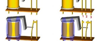
First, let's look at the diagram
The operating algorithm is as follows: when starting the engine, the daytime running lights should light up and the recorder should turn on. After turning off the engine, these devices turn off. In addition, the DRLs must go out when the side lights or headlights are turned on: this is required by technical regulations.
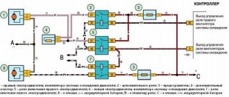
For implementation, you will need three standard 5-pin automotive relays (sold in a car store). In the diagram they are indicated by numbers 1, 2 and 3.
1. Green wire – power supply. 12 volts through a fuse are constantly supplied to contacts No. 87 (normally open) of relays 1 and 3. Output contacts No. 30 are connected to the positive inputs of the recorder and the running light module. The negative wire (ground) can be connected to the car body at the location where the devices are installed.
2. The red wire in the diagram supplies the control voltage of 12 volts, which appears after the engine starts (or turns the ignition key). In automotive circuits it is designated as “HOT RUN”. There are quite a lot of connection points: from the radio to the power supply to the fuel pump. The signal is easy to find in the description of your car.
3. When 12 volts appears on the red wire (contact No. 85), relay coils 1 and 3 are activated, the supply voltage through the green wire is turned on by the recorder and DRL (contacts No. 87 and No. 30 are closed).
4. On relay 3, control voltage is supplied through normally closed contacts No. 87a and No. 30 of relay 2. When voltage is applied to contact No. 85 of relay 2, the coil is activated and stops supplying control voltage to relay 3. The control signal comes from the side lights being turned on: The DRL goes out, but the recorder (via relay 1) continues to work.
Legality of using communication jammers
According to the Law “On Communications”, which is in force in our country, any devices that suppress signals from mobile phones or other devices are required to be certified and registered. And if a certificate can be obtained from sellers upon purchase, then you need to register the device yourself. In case of non-compliance with the rules of the current law, violators face a fine, and the use of the device is considered illegal. Although it is worth noting that people are very rarely brought to justice for the illegal use of such devices, and even when it comes to saving personal information, the risk is justified in such conditions.
Step-by-step installation process
Before starting work, it is advisable to print out a detailed wiring diagram linked to your car: with color-coded wires and power connection points. It is necessary to mark the contacts, otherwise errors during assembly may occur. The diagram adds relay No. 4 with a button to turn on the pneumatic signal and a front parking sensor switch.
Important! External connections may vary depending on the vehicle brand.
1. We carry out the wiring of wires and connectors for the relay according to the diagram.
2. Wires will inevitably cross each other; if the insulation is good, this is not a problem.
3. Contacts are crimped mechanically; a soldering iron is not used.
4. After connecting all the wires, we form bundles and place them in the corrugation.
5. To connect control and power wires, it is convenient to use a ready-made connector: in this case, from the steering column switch of a classic VAZ.
6. If the relay unit is installed under the hood, it must be covered with a standard cover. This is not necessary for salon installation.
To publish messages, create an account or log in
In most cases, they are single-tone and very quiet, and their sound can scare away only a sparrow, and not attract the attention of other road users.
We isolate everything securely. There are even ready-made blocks for relays with wires. Therefore, I decided to install a signal from GAZ.
In most cases, they are single-tone and very quiet, and their sound can scare away only a sparrow, and not attract the attention of other road users. If this is important to you, then you can install another relay at the battery that will turn on the power when you turn on the ignition, or install a signal control relay next to the battery and the power wire will be as short as possible.
Non-standard solutions
For many people, the desire to get an exclusive signal is so great that they are ready to do anything to achieve this goal. In particular, car horns that imitate husky steamships or shrill locomotive horns are becoming increasingly popular. Possessing enormous power, they will definitely attract attention to your car, but you should understand that the attitude towards this will not always be admiring. And such horns require significant space in the engine compartment.
As for the sound intensity, there are no restrictions on the part of the traffic rules, but the feasibility of such a decision is questionable. One such unreasonable signal in a populated area is enough, and you risk becoming involved in a showdown with a traffic police officer. In short, the use of non-standard sound signals on a regular car is a rather controversial decision.
Installation of wires inside the car
Power can be taken directly from the battery terminal, through a fuse. Or find the switching point in the standard fuse box (a diagram of your car is required).
Important! This box from aliexpress has input fuses for each line.
All additional wiring is done in corrugation and secured to the body with ties.
The harness is inserted into the passenger compartment through standard holes in the engine shield.
Inside the cabin, the cable is also laid in corrugation and attached to the structural elements.
All connections are made by soldering, insulated with thermocable and again corrugated.
Instructions for installing an alarm device
Installing this system on your car is carried out in several basic steps.
- First you need to find a place for the compressor. This may not be so simple. Most cars have a space under the bumper where you can place it.
- Remove the compressor from the frame, it is not needed and interferes with installation.
- The pipes can be installed on the radiator cooling system. They and other elements should not interfere with the heat transfer of all elements of the car.
- Now lay the pipes, fittings and valves. To connect the threads of pneumatic tubes, you can use FUM tape.
- Take the wires from the standard power button into the interior.
- Now you need to connect the system to the battery. It is best to do this through an additional relay, so that power is supplied only after the car is ignited.
- Lay air lines up to the air signal.
- You can make a connection through a relay, which will close the contacts of the system toggle switch and control it. It will also be activated from the standard button on the steering wheel.
- Before assembling the car body, check how everything works. Place the air intake fittings higher in the engine compartment. Check how the pressure is maintained.
Removing the Frame from the Compressor
Remember that you can always remove the air hose. It is long enough that you can use it to inflate the tires of any wheel. This is an additional advantage of installing such a signal.
Price issue
Installing a pneumatic signal on a car with your own hands
The all-pervasive horn of a locomotive or heavy-duty truck, warning us of incredible danger, cannot go unnoticed. He instills in us not only a clear warning, but also respect. A kind of reflexive instinct. Every time we hear the sound of a pneumatic signal, we have a desire to be away from the source of its radiation. Nevertheless, we sometimes feel awkward when, glancing at a vehicle emitting this incredible howl, we notice only an ordinary sedan, unremarkable among other cars, or even an SUV. So, it is already clear to everyone that the pneumatic signal is not only a certain element that attracts the attention of onlookers, but also, more importantly, a certain guarantee of your visibility in the event of preventing an accident on the road. Our article will be devoted to the topic of installing a pneumatic signal on a car. It is also worth mentioning that along with the pneumatic signal you will also receive a standardly installed wheel inflation station, because a compressed air receiver is used for the pneumatic signal. The pump and receiver will ensure the operation of not only the pneumatic signal, but also, if necessary, inflating the wheels.
The process of installing a pneumatic signal on a car with your own hands
The pneumatic signal will be installed on a KIA Sorento 3.5. In fact, a set of ready-made solutions from . This way a station capable of delivering up to 7.5 a will be used (BERKUT) SA-03)
Let’s say right away that the use of a more productive station and a station with increased pressure is not justified; for a pneumatic signal, a pressure of 5 atmospheres and an air supply of 2.85 liters, which corresponds to the volume of the station’s receiver, is quite enough. In addition, the BERKUT TG59 installation kit is used, which is actually a set of valves and adapters. An audible pneumatic signal from Cicada was also used during installation. One of the main problems is choosing a place to install the pneumatic compressor, because free space on the car is extremely limited; to understand this, just look into the engine compartment of most modern cars. As a result, the optimal installation option for the compressor turned out to be the space under the bumper.
But first, in order to compactly install the compressor, it must be removed from the frame. In this case, the compressor and receiver can be installed locally.
So, after disassembling the compressor for its further installation, we select only all the essentials that are necessary for the functional operation of our pneumatic signal. The frame on which everything was installed earlier will not be useful to us for installation.
We try on the components of the pneumatic signal. Everything will be pre-installed on the power elements of the “TV”. Here it is necessary to pay attention to the fact that the mounted elements do not interfere with the heat transfer of the radiators of the air conditioner and cooling system.
The air pneumatic signal “pipes” were installed “against the background” of the cooling radiator.
Next, service, control and regulatory equipment is installed. This is how pipelines are laid, fittings and valves are installed. When installing pneumatic pipelines, it is necessary to use FUM tape to connect the threads. This is despite the fact that the threads are, in most cases, conical, and therefore self-sealing. Control wires are routed from the standard system activation button, which will go into the cabin.
The pneumatic signal system is connected to the battery.
Best of all, through an additional relay that supplies voltage to the compressor only after voltage appears in the car’s ignition system. Air pipelines are laid to the pneumatic signal.
The system can be connected through an additional relay, which will control the standard toggle switch of the pneumatic system, closing its contacts. The relay will be controlled from the standard horn button located on the steering wheel of your car.
Before assembling all the body elements of the car, we check its functionality and the absence of leaks. In our case, the pressure is stable and remains around 6 atmospheres. The air intake and outlet fittings are located higher in the engine compartment.
This arrangement will guarantee the convenience of connecting the pumping hose and preventing water from entering the compressor unit from the route. The pneumatic system hose is easily dismantled and installed in length, and its length is 7.5 meters, which ensures inflation of any of the wheels of the machine.
As a result, we received an excellent pneumatic signal that will let all motorists who meet on your way know about you, as well as a standard tire inflation station installed under the hood of your car. Despite our sarcasm about your special position on the road, due to the presence of such a loud device. We would like to warn you about limiting the use of such a signal in unspecified cases, as this can not only prevent an accident, but also create one. After all, road users may not expect such a high-volume signal, which can simply frighten them. As a result, they may deviate from their normal behavior on the road. Treat other road users with respect and use the signal only in urgent situations that require it.
Advantages and disadvantages of a pneumatic signal
We have already listed the advantages of pneumatic signals, but it is not difficult for us to repeat them. A very loud sound level will allow you to become “noticeable” among other motorists on the road, which can prevent an accident. In addition to the pneumatic signal, you also get a standard compressor on the body of your car, which is also not bad at all. The disadvantages of a pneumatic signal include the high cost of the equipment, as well as the complexity of its connection. In addition, working with pneumatics requires high tightness of the connections, otherwise the compressor will be turned on from time to time to pump into the receiver. Such inclusions can significantly drain your battery, especially during long-term parking. In this case, it is better to connect power to the system through a relay that turns on when power appears in the ignition system circuit. In any case, the tightness of such a system will be lost much earlier than the functionality of the standard signal, which will lead to the need to replace the sealing elements and valves in it. That is, we can say about more expensive maintenance. In any case, weighing all the pros and cons and making a choice based on what is a priority for you is only your prerogative.
Pneumatic signal connection
It is turned on separately from the standard horn, by a button on the control panel. To start a powerful compressor, a relay is installed (in the diagram: No. 4). The signal itself is attached to a frame element or underbody protection.
The wiring is neatly laid out in the engine compartment.
The corrugation is lowered to the installation site, the supply wire is connected to the pneumatic compressor.
Why through a relay? A direct connection will melt the signal button after 10 presses: the pneumatic compressor current is about 15 amperes.
Important: Direct power connection (using the car's standard fuses) is not recommended. In the event of a short circuit, you can cut off power to important components of the electrical circuit.
Any additional device is connected through its own fuse.
Many car enthusiasts are not satisfied with the sound of the factory signal and want to install a pneumatic signal. Nowadays, there is a large selection of signals for a car, and here the choice remains with the consumer. From many listened signals, such as Volgovsky, HELLA, etc. The pneumatic signal still sounds louder.
Installing a pneumatic signal on a VAZ is quite simple, or rather, you can simply connect plus and minus to the compressor from the factory terminals. Next, we connect the “pipe” to the compressor and everything is ready. You can choose the location of the signal at your discretion, both behind the bumper and in the engine compartment, fortunately there is enough space.
Of course, there are some nuances in installing the “pipe”, or rather, these are blown fuses. A standard 10 A fuse usually does not cope with its purpose and, in violation of the vehicle operating rules, it is necessary to install a fuse with a higher rating, at least 15 A. Below is a video example of installing a pneumatic signal.
Also, if you want to get an even louder sound from a pneumatic signal, you can take a compressor for 2 - 3 pipes separately and put it with an adapter on one large pipe. The result will be an even shriller beep.
Pneumatic Horn A Very Scary And Loud Thing | Steam locomotive is resting, Pneumatic signal on VAZ 2110 on Pneumatic.
In this video I will tell you how to install an air suspension horn on your own and show you how it works! Erase your gift - https://bit.ly/2PNQ7W1 BONUS - follow the link! MOTORRING.RU - https://motorring.ru/?utm_source=pokayfu YouTube channel motorring - https://www.youtube.com/channel/UCo3D... 7% discount with promotional code Pokayfu or Kaif + fast delivery of goods! links to Namika (air suspension) | INsta - https://www.instagram.com/restyle_pro_/ PHONE NUMBER 8917-300-92-52 | VK - https://vk.com/kasumov_namik LINK TO KUPEVOD CHANNEL - https://www.youtube.com/c/%D0%9A%D1%83%D0%BF%D0%B5%D0%B2%D0 %BE%D0%B4 FOR ADVERTISING QUESTIONS, CONTACT DM VK. Group on VK - https://vk.com/titan_300 my Instagram - https://www.instagram.com/nemtsev_007/ link I am on VKontake - https://vk.com/id412489833 ask questions, but it’s better in the comments under the video , here I will answer faster, follow the channel, THANK YOU!!! unnecessary text: AIR HOOK IS A VERY SCARY AND LOUD THING | THE STEAM LOGO IS RESTING, vaz2112, dvenashka, pneumatic horn, pneuma, vestalime, muskarik, prioramuskarik, vaz2170, vaz2114, vestasport, grantasport, kalinanfr, kalina2, youtubehata, hhs, proshilpriu, exhauststt, tumankivpriora, pneumaticalina, AvtoVAZ, grantazerkala, lyu counter, toner machine, grantliftback , abramtv, canadaair, shakha, driftkorch, bpan, priora, artem brin, priora hatchback, lada, tuning priors, 2112, auto, boys' basin, basins are falling, black priora, combat classics, tinting, bunker, on air, pneumatic signal, Lada , Priora on pneumatic, se, cars, installation of pneumatic signal, 2170, pneumatic signal, pneumatic signal for VAZ 2110, for VAZ, for VAZ 2110, VAZ 2110, VAZ, pneumatic, signal, air signal, video, YouTube, car, pipe, tuning VAZ , 2110, tuning, lada, goodies, for the interior, goodies for the interior, car, horn, sound signal, loud signal, installation of an air signal, Igor Lakomov, Lakomov, autoling, from a steam locomotive, installation of an air horn, signal on a car, horn from a steam locomotive , lada priora, lada priora 2, lada priora 3, video diary, Lada Priora, Priora 2, Priora 3, locomotive, air horn, air horn + for a car, air horn + with your own hands, how to connect an air horn, air horn sound, air horn + for a car , air horn through a relay, air horn compressor, air horn connection, how to install an air horn, air horn price, air horn diagram, air horn connection diagram, loud air horn, how to connect an air horn through a relay, pneumatic horn, air horn, air signal, installation of air suspension, air suspension, VAZ 2109 on pneumatic, VAZ 2109 Canada, Canada Air, pneumatic signal, pneumatic signal for VAZ 2110, for VAZ, for VAZ 2110, VAZ 2110, VAZ, pneumatic, signal, air signal, pneumatic horn, video, YouTube, auto, car, pipe, VAZ tuning, 2110, tuning, lada, Lada, nishtyaki, for the interior, nishtyaki for the interior, car, horn, sound signal, loud signal, installation of an air signal, Igor Lakomov, Lakomov, hhs, hhsoundd, steam locomotive, 2112, Priora, Artem Brin, Priora hatchback, tuning Priora, boys' basin, basins are falling, black Priora, combat classic, bpan, tinting, bunker, pneumatic, pneumatic signal, Lada, Priora on pneumatic, se, cars, installation of pneumatic signal, 2170
What to pay attention to
Connection via relay 4-pin connection diagram
Although there are no requirements in GOST (except perhaps a fine for the absence of a signal), it is important to remember that high-frequency beeps are standardized, so make sure that the main frequency remains unchanged. In addition, you should not choose horns that imitate a steam locomotive or other vehicles that a pedestrian or motorist in the oncoming traffic simply does not expect to hear
Think about your health, as doctors do not recommend using signals with a frequency of more than 440 Hz. If you are planning to purchase a powerful multi-voice horn, then do not forget to take care of high-quality sound insulation in the car
In addition, pay attention to the following nuances:
- Before purchasing, you should make sure that the vehicle battery will “pull” the selected horn. If you plan to combine several beeps, the battery will discharge very quickly, since such “toys” are voracious and consume about 20-25 A.
- When choosing a horn, check with the seller whether you will need to connect the horn to power or whether you will need to purchase a compressor (which may be included) for operation.
- If you need more bass in the horn, then choose low-frequency models, and vice versa, for a subtle sound, high frequencies are better suited. For a polyphonic melody, both are used.
- Remember that voltage is different in cars and trucks. For cars it is 12 V, and for trucks it is 24 V.
Electronic signals
The main part of electronic beeps is a chip that generates a sound of the desired frequency and transmits it to the device’s loudspeaker. The signal volume can reach 110 dB, and the frequency range is very wide and can be completely different in each individual model.
Electronic horn
They can be installed on almost any car, regardless of the dimensions and voltage of the electrical circuit. Electronic horns can operate on both 12 and 24 V. The device can reproduce both single-tone sounds and various melodies.
It is worth remembering that a musical horn can cause unwanted attention from traffic police officers if the melody resembles a special signal. In this case, a fine may be imposed on the driver.
How to connect an audio signal
Having collected all the necessary elements, only now can you move on to the most important action - connection.
- The first step is how to connect a signal through a relay: remove the “-” terminal from the battery.
- Next, you need to remove the sound signal and install a relay in its place.
- Wire connection options
- A so-called “leech” is installed on the “+” wire that connected the sound signal. A wire approximately 15 cm long with male-female terminals is connected to it;
- If it is not possible to install a “leech”, you can strip the positive wire, then solder a piece of wire with a “mother” terminal to it. The soldering area must be sealed with insulating tape or pre-applied heat shrink.
- Next, the “+” wire must be connected to the relay. To do this, a wire with a newly formed process is connected to the 86th and 30th contacts.
- Let's move on, figuring out how to connect a signal to a VAZ or any other car. Now you need to connect the remaining negative wire to the relay. To do this, you need to use pin 85.
- An audio signal is connected to the remaining 87th contact of the relay.
- Last step: put the “-” on the battery.
What malfunctions can there be?
The most common cause of car horn failure is considered to be oxidation of contacts or complete oxidation of the entire mechanism.
The second most popular malfunction problem is unreliable contact connections. Over time, the connections come loose or were initially loosely secured.
The circuit for checking the sound signal in a car is always standard. The first step is to remove the battery terminals, disconnect and discharge the airbag capacitor. Then the steering wheel cover is removed; this operation must be performed with a partner.
After all the manipulations, those same oxidized contacts are cleaned; a needle file will help with this most effectively. The contacts are re-fixed in their original position.
Types of car horns
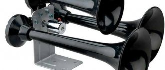
Pneumatic signals
They work on the same principle as the old horns from the days of horse-drawn carriages: a compressor supplies compressed air through a pipe, causing vibrations. All copies are in the same price category, while differing in design. Most often this concerns the shape of the horn pipe.
Pneumatic signals can have a power of up to 125 dB, and their frequency range is located at several required levels at once. This is achieved by placing four “horns” (in some cases less). Thus, the lowest signal plays at a frequency of 320–415 Hz, and the highest sound can reach up to 810 Hz. To power this orchestra, the compressor needs a pressure of at least six atmospheres. In this case, the sound of the horn will form a real melody, but this requires programming the device and a lot of space under the hood.
Electromagnetic beeps
In such equipment, the main element is an electric magnet, which is connected to the membrane. The breaker connects the current source to the core winding, and it, in turn, to ground using a signal button. Activation of the latter causes the core rod to perform oscillatory movements, which lead to vibration of the membrane. These signals differ according to the criterion of the sound emitter.
Disc horns
They have a collapsible or one-piece design. The latter allow you to save several centimeters of space. The type of execution allows you to install open and closed, respectively, in plain sight or under the hood. Standard signals are designed in a similar way, which allows you to install “pancakes” without much effort. The device can be two-tone, but single-tone ones can also be configured by combination, resulting in a synthesis of a high-frequency signal (420–440 Hz) and a simple one (335–350 Hz).
This type is more difficult to install due to the curved shape of the pipe and larger size. Signal power - 118 dB, frequency - 510 Hz. These kind of gramophones are known for putting a lot of pressure on the eardrums. A two-tone "snail" may have a relay that supplies electricity alternately to each of the windings, allowing it to produce a melody.
Pneumatic horns
The main working elements of pneumatic horns are: horn, diaphragm and membrane. When compressed air acts on the membrane, it causes it to deform and vibrate, and the resulting sound is amplified by the horn. The pneumatic horn is the loudest signal on a car - its volume reaches 145 dB.
Pneumatic horn
Powerful horns of this type are usually equipped with four tubes that generate a signal with a frequency of 400 to 800 Hz. To ensure the full operation of such a device, you will need a fairly powerful compressor capable of creating a pressure of 60 atmospheres.
A pneumatic horn is capable of reproducing not only a monophonic sound, but also some melodies. To do this, the compressor will need significant space under the hood, and the device will also need to be supplemented with a special electronic controller. The compressor for the horn is then controlled by electrical signals supplied by a programmed controller. The driver has several variations of melodies.
Air signal connection
If you need to connect not an electric, but an airborne sound signal, the connection procedure will be almost the same as described above. The difference is that the wire from the relay does not go to the sound signal itself, but to the compressor (the engine that supplies air to the signal). And the pneumatic signal pipes are connected to the compressor through tubes.
When you press the horn, air from the compressor is supplied to the horns. With the help of a membrane installed in them, a sound signal is obtained.
You can read about how to connect the headlights yourself in our article How to connect the headlights.
Lada 2106 Akkerman71 › Logbook › Prevention and strengthening of the air signal.
Hi all. The other day the air signal malfunctioned for some reason. You can clearly hear the relay operating, the abnormal, rattling operation of the compressor and the complete absence of sound. The signal is a necessary thing, in some cases necessary, so I didn’t put it on the back burner, and the weather still allows me to do something else in the garage.
I removed the compressor, cleaned it of dirt and dust, and generously poured Xado penetrating lubricant with revitalizant into it through the outlet hole. After some time, the compressor started up and work was fine.
Apparently, from time to time, the compressor needs periodic lubrication, and if you miss the “right” moment, it can completely fail. Dudke also took preventative measures, disassembled it, and lubricated the membrane with silicone grease. A year ago, when I installed this signal, I immediately liked the sound, but I felt that it lacked a little pressure produced by the compressor. And when I moved it from behind the grille, under the bumper, the distance of the air line (tube) increased, and there was a slight delay in response. Of course it worked, but I wanted it to be better. At the same time, while everything was removed, I decided to add pressure to it, so I bought another compressor. I made a new mounting strip for two compressors and secured them.
For the warm season, I'm planning to redo the engine compartment, then I'll paint the trim as it should be, for now it's temporary. I decided to lay two lines from the compressors to the pipe and place the tee close to it.
According to the connection, the second compressor was connected in the same way as the first, using a relay,
but the power supply is from the battery, and each has its own fuse, separate. For clarity, I will post the same connection diagram, the first one I came across from the network.
After installation and testing, I was pleased with the result. This signal should immediately come in a set, with two cospressors.) The problem with the delay disappeared, the sound changed a little, became higher and of course louder) exactly, just right, not so much as to put passers-by in a stupor,) but also at the right moment, something If only we had heard, this happens. Well, if one compressor refuses to work at any moment, the second one will not allow you to remain without a signal completely. Well, here's a photo:
Source
Characteristics of the pneumatic signal
Before moving on to how to make this device with your own hands, you need to understand what a pneumatic signal is. And also, what is its operating principle, what are its functions, design. And of course, the pros and cons of having such a horn on board your car.
Working principle and functions
The operating principle of the device is quite simple. Pressurized air from the compressor moves through the tube. This causes it to vibrate and make sounds of a certain frequency. Due to the certain complexity of the design, the cost of such a device is quite high . If you decide to assemble and install it yourself, you will save some money, but the costs will still be significant.
There are signals with different pipe shapes, as well as signal power, which can reach up to 125 dB (video author – Varan Varan).
Design
This device consists of the compressor itself and a tube. The number of the latter can reach up to three. The increased number of horns allows you to achieve a richer and more powerful sound. However, even with one tube, the pneumatic type signal makes a powerful impression. The design also includes a solenoid valve, a check valve, a pressure switch and a receiver.
Features of horn installation
When purchasing a car signal, you will probably find instructions for self-installation in the box, but you should understand that you should undertake such work only if you are sure that you are doing everything correctly. If there is no such confidence, then it is better to entrust the installation of an electric sound signal on a car to a specialist.
If the type of the new horn matches the type of the standard one, there should be no problems: just dismantle the old device and install a new one in its place. If the dimensions do not match, you will have to look for another place and tinker with the fastening. The most difficulties arise when installing pneumatic signal devices. Here, in addition to the horn itself, it will be necessary to install a powerful compressor, the dimensions of which cannot be compact.
In addition, the pneumatic horn compressor will consume a lot of energy, so you should make sure that the parameters of the generator and battery can ensure its operation without damaging the on-board electrical network.