On the territory of the Russian Federation, amendments to the rules of the road (TRAF) have been in force for more than 8 years, according to which a moving vehicle during daylight hours must be indicated by low beam headlights, fog lights (FTL) or daytime running lights (DRL). Using headlights and fog lights for these purposes has a number of disadvantages. Therefore, drivers prefer to buy ready-made running light modules and install them in their cars themselves. How to properly connect daytime running lights so that their operation is safe and does not contradict current laws?
GOST requirements for installing DRLs
According to GOST R 41.48-2004, do-it-yourself installation and connection of navigation lights must be carried out strictly in accordance with the following requirements:
- A distance of 600 mm must be maintained from the edge of the car body to the DRLs. It is allowed to reduce this indicator to 400 mm, but only if the overall width of the machine is less than 1.3 m (clause 6.19.4.1).
- The distance from the ground level to the light elements should be in the range from 250 mm to 1500 mm (clause 6.19.4.2).
- DRLs must be forward-facing and installed on the front of the vehicle (clause 6.19.4.3).
- A certain geometric appearance is maintained. According to paragraph 6.19.5, the horizontal angle beta should be 20 degrees inward and outward, and alpha should be 10 degrees downward from the horizontal and upward.
At the same time, a specific connection diagram for running lights is not reflected in GOST in any way, so here you are free to make a decision yourself. However, there is a small nuance. Installing running lights in accordance with GOST also implies automatically turning on the DRLs together with the car engine and turning them off when the headlights are working. The only exception is turning on the high beam headlights for a few seconds to signal other drivers.
Based on these requirements, the choice of navigation lights must be approached carefully.
Main conclusions
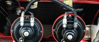
As standard, the Lada Granta car is equipped with low-power incandescent light bulbs in the running light system, which are not distinguished by good brightness and durability. Their replacement is likely with subsequent other light sources:
The first ones belong to the group of high visual comfort, have good brightness and speed of installation. But during installation, they can simply be damaged by putting a grease mark on the surface of the test tube, not to mention that the stronger they are, the less they serve. LEDs do not have such disadvantages, consume less energy, save battery resources and are very durable. Their main drawback is the formation of blue reflections and the originality of the base, which complicates the replacement function. In addition, LED bulbs can trigger sensors on the dashboard.
Source: svetilnik.info
How to choose running lights
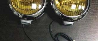
The stores offer a wide selection of DRLs from a variety of manufacturers, in various configurations and colors. However, not every lamp is suitable for use as navigation lights. For example, halogen and xenon lights will not withstand constant operation; they will “eat” a lot of energy and discharge the battery. Incandescent bulbs are also not the best choice, but LEDs are considered the best when installing DRLs.
There are also many LED running lights. The best products are those in glass housings and lensed LED DRLs for foglights. The rest (on rubber bands, “eagle” and “dragon” eyes, in the form of SOV platinums) do not meet the requirements stated by GOST.
Before connecting the daytime running lights yourself, make sure that:
- DRLs match the shape, type and design of your car's bumper.
- The size of the DRL unit, which is selected based on where the running lights will be installed (in the air intake or on the bumper), allows you to mount them in your car.
- The number of LEDs in the block does not exceed 5 pieces for each. If the light is too bright, the daytime lights will shine like “dimensions”, which is unacceptable.
- The luminous intensity of the DRL should be no less than 400 cd and no more than 800 cd, and the temperature range of the lamps should be from 4,300 to 7,000 K.
- Running lights emit pure white light (yellow and blue products are prohibited).
Types and causes of failure
These devices have several types:
- low beam headlights. Turned on during vehicle operation. In Russia it is allowed to use them as a light source for daytime driving;
- high beam headlights. Operate at reduced voltage. This helps to reduce the intensity of light, which in some cases does not help increase the visibility of pedestrians and cyclists on the road;
- fog lights. Their implementation in the Russian Federation is permitted (clause 19.4 of the traffic rules);
- front turn signals;
- individual light sources in front of the vehicle with specific light intensity patterns.
Headlight Lada Granta with LED lamps
The main manufacturers of high-quality DRLs are brands such as:
These and other models of light sources may differ in shape (rectangular, round, oval), the number of diode bulbs inside, power, and brightness.
Now manufacturers have even begun to produce silicone diode bulbs suitable for the Lada Granta. They can be placed on one or several tapes.
Among the main reasons why DRLs do not glow are:
- lack of polarity check before installing light sources;
- the turn signal channel does not light up;
- fuse is blown;
- lack of heating or burnout of the filament.
In order to improve daytime running light sources and make them as useful and elegant as possible for the car enthusiast, all stages of the work must be done very carefully. Instead of conventional lamps, which do not glow very brightly, you can install LED lighting without a base assembly. You can purchase these components in virtually any store that has spare parts for cars. With all this, when making a choice, you need to focus on models with greater lighting brightness.
Operation of LED lamps
What you need to install DRLs yourself
For work you will need the following materials and tools:
- Any crimping device, such as pliers.
- Wire cutters.
- Blowtorch and lighter. The latter will be required to tighten the heat-shrinkable tubes.
- 3-4 meters of insulated two-core wire, for example, PVA 2x1.5 or 2x0.75 (required when connecting two DRL units in parallel).
- Any sealed contact (reed switch).
- A single-core wire with a diameter of about 1.5-2.5 mm and a length of about 3 meters.
- Plastic clamps.
- A regular four-pin 12V relay.
- LED DRLs.
You should also make sure there is a clean, dry place where you will be working. After this, you can begin to install additional lighting elements.
First of all, decide where exactly the daytime running lights will be mounted. Some cars already have ready-made holes for additional fog light modules, while other cars use the radiator grille for DRLs. The last option is the best, since in this case you will be able to maintain all the necessary distances and boundaries.
Simply remove the radiator grille and cut out the holes for future lights yourself. It is important to remember that the light must be supplied at a certain angle. You may need to make an additional hole for this.
Grant ECU pinout
The Lada Granta uses two types of electronic engine control units. Fundamentally, the systems differ slightly, which excludes the possibility of their interchangeability.
| Contact | 11183-1411020-51/52 | 11186-1411020-21/22 |
| A1 | DPKV | |
| A2 | Not involved | |
| A3 | Entering the first knock sensor | |
| A4 | Not used | |
| IN 1 | DPKV | |
| AT 2 | Not involved | |
| AT 3 | Input of the second knock sensor | |
| AT 4 | Main relay output | Not used |
| C1 | Empty | |
| C2 | DTV | |
| C3 | Mass air flow sensor | |
| C4 | UDC | |
| D1 | DDC weight | |
| D2 | Empty | |
| D3 | DTOZH | |
| D4 | Not applicable | |
| E1 | Zeroing the TPS | |
| E2 | Empty | CAN L |
| E3 | Empty | CAN H |
| E4 | Canister purge valve output | |
| F1 | Body from DTV | |
| F2 | Speedometer input | |
| F3 | Not applicable | DFM |
| F4/G4/H4/J4 | Output from injector No. 1/2/3/4 | |
| G1 | Antifreeze temperature sensor ground | |
| G2/G3 | Not used | |
| H1 | On-board electronics grounding | |
| H2 | UDC | |
| H3 | Not involved | Battery charge indicator output |
| J1 | Terminal No. 15 from the ignition switch | empty |
| J2 | Entrance No. 2 TPS | |
| J3 | DDC | |
| K1 | Supplying voltage to the TPS | |
| K2 | Entrance No. 1 TPS | |
| K3 | UDC | |
| K4 | DDK heater power connector | |
| L1/M1 | Leads to the ignition coil ¼ and 2/3 cylinders respectively | |
| L2/M2; L3/M3 | Not involved | |
| L4/M4 | Throttle actuator pin 5/6 | |
DRL connection diagrams
Since DRL can be mounted at your discretion, there are many connection schemes that allow you to configure the optics in the most convenient way for the driver. Let's look at the most popular of them.
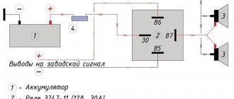
Option 1 (to speed sensors)
This connection of running lights through a relay, the diagram of which is shown below, is considered one of the simplest. In this case, the DRLs will turn on depending on the operation of the speed sensor. In order to implement this scheme, it is necessary to connect contacts K1.1 to the circuit section (into the wiring break) from the low beam switch button to contact 85. In this case, you can use any relay with an opening pair, but experts recommend using a product with a TC code.
If you want the dipped lights to work while the engine is on, rather than the side lights, then the contacts must be “paralleled.”
Option 2 (to the oil sensor)
Another scheme for connecting daytime running lights via a relay uses an oil sensor. You should immediately check that it is in good working order, since if the regulator provides incorrect information about the fluid pressure, then the operation of the entire system will be disrupted.
With this installation of DRLs, the lights will turn on when the engine starts, and will be turned off by the dimensions. As optics, you can also use low beam or fog lights.
Option 3
It will be a little more difficult to connect the DRLs so that they turn on when the engine starts and turn off when it stops. In this case, the running lights will turn on together with the low beam headlights. This will require two low-power diodes (for example, 1A + KD10), which must be connected in series. After this, wires about 400 mm long are soldered to the light bulbs and connected. Don't forget that they are polar.
At the next stage:
- Dismantle and disassemble the dashboard of the car and connect the “blank” to X1 (most often the yellow wire).
- Remove the button through which the optics will be turned on.
- Plug the other end of the wire into the connector.
- Reinstall the button and check its functionality.
Option 4 (connecting running lights from the generator)
To implement such a project, you can use one of three schemes.
The first one is suitable if only the handbrake and the engine are used.
The second scheme for connecting running lights from the generator will require the use of an additional resistor, which is responsible for turning off the daylight when the side lights or headlights are activated.
The third scheme will allow you to deactivate the running lights:
- When you raise the handbrake, during the start of the internal combustion engine or during the automatic start of the engine along with the alarm.
- When the lights are turned on (in this case, it is necessary that the headlights or fog lights operate normally).
Roughly speaking, this type of connection “cancels” the automatic start of the DRL simultaneously with the ignition of the generator.
Healthy! It is this scheme that is “working” when passing the GTO.
Before connecting the running lights from the generator, it is recommended to watch the video at the end of the article. The fact is that there is more than one or two ways to activate the DRL. However, the connection will be much easier if you purchased a ready-made set of running lights.
Option 5 (connection of a ready-made kit)
In order not to rack your brains over how to install running lights on a car yourself, the easiest way is to buy a ready-made control unit to automatically turn off and turn on the DRLs. To install this module you need:
- Connect the black wire to the negative of the battery, and the red wire to the positive.
- The orange wire (if included) must be connected to the headlights or low beam. If the wire is not connected, the lights will not deactivate when the low beam or side lights are turned on.
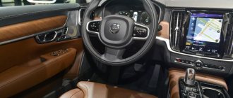
Description of the Grants instrument board
All information from the sensors is displayed on the Lada Granta instrument panel in the most convenient and practical way for the driver to quickly familiarize himself with it, so as not to distract him from the road situation. The location of the indicators is thought out to the smallest detail; all necessary and important readings can be easily seen by looking below the top edge of the steering wheel. Secondary data is placed a little further away. The panel illumination does not distract the driver at night; all indicators are clearly visible at any time of the day. The panel includes:
- tachometer;
- engine control check indicator;
- left and right turn signal indicator;
- low oil level indicator;
- ABS warning light;
- immobilizer warning light;
- overheat indicator;
- brake system indicator;
- battery indicator;
- speedometer;
- ESC performance indicator;
- air cushion indicator;
- belt indicator;
- low fuel level sensor;
- flat tire indicator;
- electric amplifier indicator;
- Lada computer display;
- door open sensor;
- indicator for high or low beam headlights;
- front and rear fog lamp indicator;
- daily counter reset button.
The nuances of turning on running lights
The basic requirements regarding installation, technical parameters and connection of navigation lights are listed in paragraph 6.19 of GOST R 41.48-2004. In particular, the electrical functional circuit of the DRL must be assembled in such a way that the running lights turn on automatically when the ignition key is turned (the engine starts). In this case, they should automatically turn off if the headlights are turned on.
Clause 5.12 of this standard states that headlights (FGS) should be turned on only after the lights are turned on, with the exception of short-term warning signals. When connecting DRLs yourself, this feature must be taken into account.
Correct connection of DRLs is not limited to a well-thought-out functional diagram. It's time to think about the stabilization unit for LEDs. In the running lights themselves, resistors act as a current limiter; however, due to voltage drops, resistors cannot limit the current to the same level. That is why a voltage stabilizer in the running lights connection circuit is extremely necessary. Otherwise, the service life of LED DRL modules is significantly reduced due to constant changes in on-board voltage. Some car enthusiasts claim that it is possible to connect running lights without a stabilizer.
Connecting and installing an LED driver is a waste of time, because the DRLs on LEDs shine regularly for months without any stabilization...
However, this statement is easy to dispute. The fact is that with each voltage surge, more than 12 V appears on the LED module, the forward current through the LEDs exceeds the nominal value, which leads to overheating of the emitting crystal. The brightness of the LEDs decreases, such DRLs will no longer be able to fulfill their immediate task - to warn oncoming drivers from afar, and over time they will begin to flicker and fail.
Using LED DRLs without a voltage stabilizer means spending at least several hundred rubles every year on new modules and wasting time replacing them.
For ease of understanding, the circuits below are shown without using a stabilizer.
High visual comfort lamps
Although the standard lamps with a dull yellow color in the running light system may still remain fully operational, almost all Lada Granta owners strive to immediately replace them with halogen ones with a catchy snow-white light. The reason for this is an increase in visual comfort. It is also noted that this can highlight the exterior profile of the car.
Halogen light bulbs from the following manufacturers are most popular among car enthusiasts:
- Philips.
- Lighthouse.
- OSRAM.
- IPF.
- General Electric and some others.
Like other modifications, halogen lamps for DRLs have the same corresponding number of shortcomings. This is primarily due to increased heating and, as a result, the shelf life decreases with increasing power. For this reason, when choosing similar sources for the Lada Limonka, you should take into account that they can be produced in 2 versions:
Option 1 meets all legal requirements, but at the same time has average durability. The 2nd is the most economical and, although it does not shine as brightly, it lasts longer.
Pay attention! The grease mark left on the surface of the test tube when replacing it can significantly reduce the service life of a halogen lamp. Therefore, when reinstalling, it is imperative to wear cotton gloves, and after installation, wipe the surface of its glass with clean alcohol wipes (if contamination has been applied).
Switching on through dimensions or low beam
The second version of the DRL connection diagram involves using the power circuit of the side light bulb. To do this, the positive wire from the running lights is directly connected to the “+” from the battery. In turn, the negative wire is connected to the “+” of the side light, which is currently electrically neutral. As a result, the following current flow path is formed: from the “+” of the battery through the LEDs to the size, and then through the light bulb to the body, which serves as the minus of the entire circuit. Due to the low current consumption (tens of mA), the LEDs begin to glow, and the lamp spiral remains extinguished. If the driver turns on the side lights, then +12 V appears on the positive side of the side lights, the potentials on the DRL wires are equalized and the LEDs go out. The circuit goes into normal mode, that is, current flows through the side light bulbs.
This circuit solution has several disadvantages:
- running lights remain on when the engine is turned off, which is contrary to current regulations;
- the circuit will not work if LEDs are also installed in the dimensions;
- the circuit will not work correctly if the DRLs contain powerful SMD LEDs, the rated current of which is comparable to the current of a light bulb;
- For safety reasons, an additional fuse must be installed.
Scheme of VAZ-2190 Lada Granta
A complete collection of electrical equipment and wiring diagrams for the Lada Granta (VAZ-2190). Including relay and fuse blocks, as well as repair and maintenance manuals, which can be downloaded for free and without registration using the links at the end of the material. The information will be useful to both professional auto electricians and amateurs with some knowledge of electrical engineering, which will allow them to carry out simple repairs with their own hands. For 2022 there are 6 Lada Granta models:
- Granta sedan
- Granta liftback
- Granta hatchback
- Granta station wagon
- Granta Cross station wagon
- Granta Drive Active sports sedan version
The electrical circuits are almost the same, with some minor differences, that is, the circuits offered here are suitable for any modification of the Grant.
Connection via a 4-pin relay from a generator or oil sensor
The following two methods have a common basis and imply the operation of daytime running lights only after the engine is started. The circuit for switching on DRL from the generator is based on switching a four-contact relay and a reed switch.
The DRL relay contacts are connected as follows:
- 30 – to the positive terminals of LED modules;
- 85 – to the positive wire to the dimensions;
- 86 – to any reed switch output;
- 87 and the second terminal of the reed switch - to the “+” of the battery.
After checking the reliability of all contacts, proceed to setup. To do this, start the engine and, by moving the reed switch near the generator, achieve its activation and a stable glow of the DRL. Then the reed switch is hidden in a thermal tube and fixed in the found place using nylon ties.
At the moment of starting the engine, and then the generator, the contacts of the reed switch and relay close, supplying power to the LED running lights. In this case, the side lamps remain turned off, since the current through the relay coil is small to light them.
In the absence of a reed switch, you can power the DRL from the oil pressure sensor. In this case, pin 86 is connected to the oil pressure lamp. The rest of the circuitry is duplicated.
Both schemes have a common drawback. They cannot be used if LEDs are installed in the dimensions.
Additional indicators on the panel
The LCD display on the panel displays information from the on-board computer.
The open door indicator glows red if one of the doors is not closed. The low fuel indicator indicates the need to refuel (ignoring this signal may lead to failure of the fuel pump). The weak tire indicator illuminates when tire pressure is low. If the driver is not wearing a seat belt, the seat belt sensor lights up. The airbag status indicator lights up in cases of system malfunction; you must contact a service station, since the airbag may inflate randomly. If any indicator fails, you can ring the system and find the reason; the pinout of the instrument panel will help with this.
Connection via 5-pin relay
Now it's time to learn how to connect running lights via a five-pin relay. The scheme is the most universal, and was assembled to eliminate the disadvantages of previous options.
First, about connecting the relay for DRLs:
- 30 – to the positive terminals of LED modules;
- 85 – to the positive wire of the side lamp;
- 86 – on the car body;
- 87a – to “+” from the ignition switch;
- 87 – do not connect (isolate).
The circuit with a five-contact relay works as follows. When you turn the key, +12 V is supplied to the DRLs, thereby turning them on. If you turn on the side lights or headlights, the relay will open contact 87a and close inactive contact 87. As a result, the DRLs will go out and the side lights will turn on. The circuit fully complies with the requirements of GOST and traffic regulations and can work with side lights even based on LEDs.
However, the circuit still has one negative point - the DRLs will turn on immediately after turning the ignition switch. That is, if you turn the key in the ignition but do not start the car, the DRLs will light up.
Despite the existing drawback, the circuit is quite successful, but in order to correctly connect the DRL via a five-pin relay, you will need to supplement the circuit with a voltage stabilizer.
This switching option is interesting because the path of current flow through the running lights is independent. This allows you to install light sources of any type and power in headlights and DRLs.
On-board computer readings
A liquid crystal display is an electronic device that displays trip information, which is generated and analyzed by a computer. Based on the configuration of the car on the Lada Granta, the instrument panel is installed with 3 types of electronic “brains”, differing in the amount of data reflected.
The display shows information:
- the first line is a gear shift hint (automatic transmission indications);
- Position 2 shows the entire or daily mileage;
- Line 3 displays the ambient temperature or computer functions;
- Position 4 indicates the fuel level.
The Lada Granta has a fairly good instrument panel, the instrument panel data is legible and understandable, can be quickly found and read while driving. The instrument cluster of the Lada Granta is not oversaturated with information, has a pleasant background, it has a clear pinout (if adjustment or repair is needed) and a good view through steering wheel.
This article provides a schematic electrical diagram for connecting the Lada Granta instrument panel. The diagram shows the connection of the mounting block (assignment of fuses and relays), instrument clusters, connection of lighting controls, electric power steering, interior heater, etc.
Rice. 1 Diagram of the VAZ-2190 instrument panel (Click on the picture to view in full size)
Each wire is marked, it indicates which element it is stretched to, and through the fraction to which contact of this element. Below is a description of the elements, according to the diagram below:
1,2 — panel wiring harness block to the front wiring harness; 3.4 — panel wiring harness block to the rear wiring harness; 5 — vehicle lighting control module (dimensions, low beam, hazard warning lights); 6 — ignition switch (mechanical); 7 — on-board computer mode switch (located on the steering column switches); 8 — windshield wiper switch; 9 — instrument cluster; 10 — light signaling switch; 11 — trunk lock drive switch; 12 — diagnostic block (for connecting diagnostic equipment, clearing error codes); 13 — block of the wiring harness of the instrument panel to the block of the wiring harness of the air supply box; 14 — rear window heating switch; 15 — alarm switch; 16 — brake light switch (brake light switch); 17 — block of the instrument panel wiring harness to the radio (acoustic wires to the speaker installation location); 18 — block of the instrument panel wiring harness to the radio (radio power supply); 19 — device rotating on the steering wheel; 20 — driver airbag module; 22 — mounting block; 23 — electric power steering; 24 — cigarette lighter; 25 — backlight lamp for the heater control panel; 26 — lighting lamp; 27 — block of the instrument panel wiring harness to the block of the ignition system wiring harness; 28 — Lada Granta controller is used from Lada Kalina (model 11186-1411020-22); 29 — clutch pedal position signal switch (the car will not start without the clutch depressed); 30 — electronic gas pedal; 31 — additional resistor (to select the speed of the heater fan); 32 — electric motor of the stove; 33 — heater motor switch; 34 - control unit for the door lock system.
DRL control unit
The most reliable and simplest option is to connect DRLs without a relay, but using a special running lights control unit. It ensures that the DRL turns on after starting the engine, guarantees safe operation, protects against overloads and can be installed on cars with any type of lamps, including LEDs.
Unfortunately, among the variety of industrially manufactured DRL units, the vast majority do not comply with GOST and have mediocre build quality.
This applies, first of all, to products from AliExpress, which do not meet the requirements in almost all respects.
Among all the diversity, only 2 options can be noted: the Russian DayLight+ DRL control unit and German products from Philips and Osram. The DayLight+ control unit was developed by Russian radio engineer Fedor Isachenkov, taking into account all the features of the vehicle’s on-board network and has a number of positive aspects:
- there is built-in voltage stabilization;
- full compliance with GOST;
- the maximum long-term load power is 36 Watts (significantly less is required for DRLs);
- simplest connection diagram.
In addition to the points described above, the DayLight+ unit is universal and is suitable for all cars with an on-board 12-volt network, and also has good build quality and a high degree of protection from moisture and dust.
German products from Philips and Osram also have all the above-described advantages of the DayLight+ unit, however, German control units are supplied only together with daytime running lights and are more expensive.