Electrolysis, well known from school chemistry lessons, is very productively used in our cars, including OK. Unfortunately, not for the benefit of the car owner, but for the benefit of the car manufacturer, who once again saved money on us. We are talking about a sound signal and a relay (or rather, its absence).
Let me remind you that electrolysis is a redox process that occurs on the electrodes when a direct electric current passes through a solution or melt of electrolytes.
The connection diagram for the sound signal in OK is such that “+” is applied to the signal constantly, and the circuit is closed by “-” with the signal button on the steering wheel. We add not the most favorable operating conditions for the car, namely moisture and dirt, and we get everything that we “need” for electrolysis, read - rotting of wires and contacts.
Connecting an audio signal through a relay solves two problems at once - connecting an audio signal according to a competent circuit and the ability to connect a Volgovian audio signal (due to the fact that in it the “-” is transmitted throughout the body and cannot in any way be closed by a button on the steering wheel; you can, of course, play around with dielectric signal mounts, but the method indicated below is much simpler and more effective).
To implement a competent scheme for connecting and installing Volgov signals, we will need:
Wire (length depends on where the signal is installed, in my case about 1.5 m was enough); Terminals “mother” - 4 pcs.; Terminal “male” - 1 piece and “leech” or soldering in place; Relay; A set of Volgov signals for high and low tones (as of 05.2005 - 320 rubles).
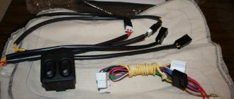
Photo 1:
The 1 set of wires shown in the photo can be made in a quiet home environment by first measuring the length of the required wire. With soldering it will take about 10-15 minutes depending on your qualifications. The 1 mounting kit shown in the photo is enough to install two Volga signals without additional soldering and crimping on site, which will take about 10 minutes. It is more convenient to carry out the work with the radiator grille removed (6 screws).
Standard audio signal connection diagram
Modernized audio signal connection diagram
Sequence of actions for installing audio signals:
Remove the “-” from the battery;
We remove the original sound signal;
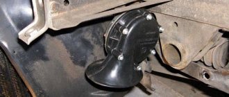
We install the relay in its place, having first slightly enlarged its ear with a drill or round file (photo 2);
On the positive wire that went to the sound signal (in my case it was red, you can check it with a test light by throwing the second contact of the light bulb onto the body), at a distance of about 10 -15 cm from the terminal we install a “leech” and connect the “mother” wire into it. - “dad” (see photo 1). Second option: instead of installing a “leech,” we strip the positive wire and wrap a wire about 10–15 cm long with a “mother” terminal at the other end to it. It is advisable to solder this connection.
Next, we connect the positive wire with the extension to the 30th and 86th contacts of the relay in any order;
We connect the remaining wire that went to the “-” signal to the 85th contact of the relay;
To the remaining 87th contact of the relay we connect a double wire (see photo 1), the ends of which go to sound signals;
We put “-” on the battery.
Photo 2:
The signals themselves are placed as desired. In my case, the signals were installed on the spare tire mount (photo 3), due to the fact that it was not used for its intended purpose.
Photo 3:
A horn or horn is a safety element that should be functional in any car. Thanks to this device, accidents can be prevented, which is why its performance is very important. What to do if the horn does not work, and how to connect the signal after repair? You will find answers to these questions below.
How does a car horn work?
Let's consider a universal diagram of a car sound signal:
- The so-called anchor.
- Device rod.
- Nut for adjustment.
- Lock-nut.
- The first tungsten contact of the horn.
- Another tungsten contact.
- Capacitor element.
- Core.
- The housing that contains all the components.
- Activation button located on the steering wheel.
- Resonator disk.
- Membrane.
- Winding.
- This is a relay contact.
- Another anchor.
- Relay coil.
- Signals.
In accordance with the connection diagram, when the driver presses the control button, a current begins to pass through the winding, which ultimately magnetizes the core, which in turn attracts the armature. With this anchor, the rod that bends the membrane begins to move, and thanks to the nut, the contacts open, which helps interrupt the electrical circuit. All elements, in particular the disk, rod, anchor and others, return to their original position using a spring and membrane. In this case, the contacts close, which again leads to the passage of current through the winding. The process of opening the contacts is carried out by pressing the horn button on the steering wheel (the author of the video is the channel pribambas sender).
Legality of using communication jammers
According to the Law “On Communications”, which is in force in our country, any devices that suppress signals from mobile phones or other devices are required to be certified and registered. And if a certificate can be obtained from sellers upon purchase, then you need to register the device yourself. In case of non-compliance with the rules of the current law, violators face a fine, and the use of the device is considered illegal. Although it is worth noting that people are very rarely brought to justice for the illegal use of such devices, and even when it comes to saving personal information, the risk is justified in such conditions.
Possible malfunctions: signs and causes
By what signs can you determine that a car horn needs repair:
- The steering horn does not work. When the driver presses the steering wheel button, the sound device does not work.
- The device sometimes works, sometimes it doesn’t. When you press the button on the steering wheel, the horn first sounds and then disappears.
As for the reasons why a device may fail, there are many:
- A fuse located in the fuse block under the hood or inside the vehicle has blown. In case of such a problem, the operation of the horn can be restored, since it is not damaged. The car may also, in addition to the fuse, have a relay.
- The horn itself is broken. If you replaced the safety element, but this did not help solve the problem, then you need to check the horn itself. To do this, the device will need to be removed, and its contacts will need to be connected directly to the battery. When connected directly, a functional horn will sound.
- In some cases, the reason lies in the appearance of a short circuit in the vehicle's electrical network. A short may affect the connection circuit, so you must first check the functionality of the fuse socket. Sometimes the horn may not work correctly due to circuit damage and current leakage.
- Also, the cause of the malfunction sometimes lies in worn-out clamping contacts located on the steering column. A malfunction of this type is more typical for domestic cars. As a result of long-term use, the springs begin to wear out over time, which leads to the fact that the impulse through them cannot be transmitted from the button to the buzzer itself.
- It also happens that the slip ring wears out right on the steering wheel.
- If the contacts are not worn out, then they could simply oxidize. Long-term use, as well as lack of maintenance, lead to deposits forming on the contacts over time. As mentioned above, this problem can cause difficulty transmitting the signal to activate the buzzer.
- The contact blades are located under the steering wheel hub. This petal may burst over time; sometimes the cause should be sought in the jamming of the pressure rack.
- The horn winding is burnt out.
- Sometimes the horn malfunction is due to a damaged electrical connection or an accidental disconnection of the terminal directly on the signal itself.
- Sometimes the reason for a non-working signal may be a break in the cable on the steering wheel on cars equipped with an airbag (video published by the channel Learning to drive a car. All secrets for beginners).
Alternative options
In this case, the possibilities are limited solely by the imagination of the Vesta owner. Most often, sound signals from the Volga are installed on the Lada, since their sound is much louder. But there are other ways. The most common options for such “modernization” are:
- installation of signals from the Volga - in this case, different installation methods are possible (with connecting a relay in the cabin or under the hood)
— installation of other signals;
— installation of a signal with an integrated compressor;
— a combination of signal and high beam.
Setting other signals is just one of many options.
Installation of signals from Volga
It involves not only installing “shells” directly on Vesta, but also various options for connecting them. It is worth remembering that the sound signal from the Volga can be either old or new. However, they have no differences, except for a slight difference in tonality:
Do-it-yourself signal diagnostics and repair
How to check and repair the horn yourself? For diagnostics, you will need a tester (preferably a digital multimeter, but if you don’t have one, you can use a regular one), crimping pliers, pliers, and a utility knife. Prepare spare wiring and a service manual for the machine.
Checking with repairs is performed as follows:
- The functionality of the fuse and relay is checked; you need to find the mounting block. A more precise diagram is indicated in the technical documentation, but usually the safety device is located in the power supply unit; it can be installed in the dashboard. Once you have located the block, examine the diagram on the back of the block cover to find the fuse. Dismantle the device that is responsible for the operation of the horn and carefully inspect it - if there is an open circuit, this indicates that the fuse is not working.
- But if the device is intact, this does not mean that it is functional. You need to diagnose it using a tester. Set the multimeter to the resistance measurement mode with sound (if we are talking about a digital tester and it has such a function). If you have an analog multimeter, before diagnosing you will need to calibrate the tester; to do this, short-circuit its probes with each other and move the regulator to zero. Then press the tester probes against the contacts of the safety device. If the part is working, then the multimeter will show 0 Ohm, but if not, then if there is no change on the display, we can conclude that the resistance is too high. This indicates a broken fuse and the device needs to be replaced.
- After this, if the fuse is working, you need to find the relay block, which is located either in the engine compartment or in the interior of the car - use the service book to search. Typically the relays are located in the same fuse box. The easiest way to check the operation of the relay is to swap the devices with other similar parts. In most cases, relays are interchangeable, so if after replacing the device the horn starts working, then you can understand that the reason was in the relay.
- You should also check the steering horn switch; a tester is also used for this. If there is no power supplied to it, then of course the button will not be able to respond to pressing.
- Next, diagnose the functionality of the relay switch. To do this, you will need to dismantle the relay and set the resistance measurement mode on the multimeter. One contact from the tester should be brought to the relay switch connector, and the second is connected to the negative terminal of the battery. With this connection, the assistant must press the beep button. As a result, numerical values should appear on the display. If the message Out of Limits appears on the screen, this indicates that the switch is not in working condition, and accordingly, it needs to be changed.
- It would be a good idea to check the horn itself. As a rule, the horn device is located behind the engine radiator grille, directly in front of the main radiator device. Having found the mechanism, you need to determine which of the conclusions is positive and which is negative. Please refer to the technical manual to determine this accurately. Once you know this, connect the horn directly to the car's battery to check its operation. The positive contact is connected to the plus, the negative, respectively, to the minus. When the negative contact is connected, the horn should start working, but if the connection does not produce results, then the device is faulty.
- The next step will be to diagnose the circuit. If you have any suspicions about the health of the electrical circuit, you need to check the grounding of the circuit, as well as the voltage and current values. Determine the mass to accurately identify grounding; for diagnostics, set the tester to measure resistance in Ohms. Connect one contact of the multimeter to the minus of the circuit, and connect the second to ground. As a result, numbers should be shown on the tester screen - if they are present, the wiring is intact. At this stage, you need to check the condition of the contacts. As practice shows, often the cause of failure lies in their oxidation, so it makes sense to clean the contacts.
Settings
- Devices
- WallSwitch
- Settings
| Settings | Meaning |
| First field | Relay name, can be edited |
| Room | Selecting the virtual room to which the device is assigned |
| Relay operating mode | Selecting the relay operating mode: |
- Pulse - WallSwitch, when activated, emits a pulse of a specified duration
- Bistable - WallSwitch, when activated, reverses the state of the contacts
Opens the script creation and configuration menu
Allows the user to disable a device without removing it from the system. The device will not execute system commands or participate in automation scripts. All device notifications and alarms will be ignored
The standalone controller CTV-CR20EM with a built-in Proximity card reader EM-MARINE is designed to build an autonomous access control and management system for one or two access points.
The controller is made of impact-resistant plastic and has an IP68 protection class, which allows it to be used in various climatic conditions. The stand-alone controller CTV-CR20EM is programmed from the remote control or using master cards that are supplied in the kit.
CTV-CR20EM supports 10,000 user keys and allows you to implement the “gateway” operating mode when using a second similar controller.
ATTENTION: The manufacturer reserves the right to make design changes not reflected in these instructions, which do not lead to a deterioration in the declared characteristics, at any time and without prior notice.
PURPOSE OF CONTROLLER CONTACTS
Pink wire RESET - used to reset settings Pink wire GND - used to reset settings Green wire D0 - Input for connecting the reader data circuit White wire D1 - Input for connecting the reader data circuit Gray wire ALARM - connecting a siren Yellow wire OPEN - Exit button or call button video intercom panel Brown wire D_IN - connection of the door open sensor Red wire + 12V - +12V power contact from the power supply Black wire GND - "Ground" and common negative Blue wire NO - relay contact, normally open (open) Purple wire COM - common relay contact Orange NC - relay contact, normally closed (closed)
ACS CONTROLLER CONNECTION DIAGRAM
Main modes 1. Using the device in standalone controller mode with a built-in reader.
2. Using the device in controller mode with connecting an additional reader with Wiegand26 output
CONNECTION DIAGRAM FOR TWO CONTROLLERS
Additional modes 1. Using the device in the mode of two controllers for one door. In this mode, the first controller is installed indoors and is used as a controller, the second is installed outside and is used as a reader. Enable GATEWAY mode on all devices. With this scheme, the number of users can be increased to 20,000. To combine user databases, the settings on the two devices must be identical, including the administrator master code.
2. Using the device in the mode of two controllers for two doors (“GATEWAY” mode) In this mode, install one controller on the first door, the second on the second. Enable GATEWAY mode on all devices. With this scheme, the system will work as follows: while the first door is open, the second will always be closed. After closing the first door, you can open the second one.
3. Using the device in Antipassback mode for one door. Install the controller indoors and the reader outside. Enable Antipassback mode in main mode. With this scheme, the system will work as follows: the user presents the card at the entrance and exit. The user will not be able to log in or log out twice in a row.
4. Using the device in Antipassback mode for two doors. Install the first controller on the first door and enable Antipassback mode in additional mode. Install the second controller on the second door and enable Antipassback mode in the main mode. The user will not be able to go through the same door more than once without going through a second door.
CONNECTION DIAGRAM OF THE CONTROLLER TO THE VIDEO DOORPHONE
The figure shows a diagram of connecting the controller to the calling panel of the video intercom and the electromechanical lock.
To connect the calling panel to the controller using an electromechanical lock, the following contacts are used: “COM” - common relay contact and “NO” contact - normally open relay contact.
The “COM” wire from the calling panel is connected to the “OPEN” controller contact
The “NO” wire from the video intercom calling panel is connected to the “NO” controller contact, and one of the wires from the electromechanical lock is also connected here. The second conductor of the lock is connected to the common “Minus” of the power supply. Thus, the lock will be opened both from the video intercom and using cards or keys programmed into the controller.
Note! For different manufacturers of calling panels, the colors of the “COM” and “NO” contacts may differ.
CONTROLLER INDICATION MODE
Standby mode - The indicator light flashes red. There is no sound indication.
Relay activation - Indication light lights green. The sound indication gives a short signal.
Entering programming mode - The indicator light turns red. The sound indication gives a short signal.
Successful operation - Indicator light turns green. The sound indication gives a short signal.
Error - There is no light indication. The sound indication gives three short beeps.
Exiting programming mode - The indicator light flashes red. The sound indication gives a long signal.
Alarm - Indicator light flashes red. The sound indication gives a continuous signal.
Setting a more powerful sound signal through a Yamaha YBR 125 relay
Axline
Guest
I decided to change the sound signal to a more powerful one.
There are two types of sound signals: noise hornless and tonal horn. Hornless signals are considered to be shriller and more difficult to hear, and are recommended for use on highways and in noisy environments. Horn (snail) ones are more suitable for urban conditions. Horn signals are usually installed in pairs (high and low tones). For myself, I settled on the hornless option (loud and shrill).
At an auto parts store I bought a horn from a new VAZ, large and with two terminals ((+) and (-), the old ones come with “snails” with one contact (+) and grounding to ground). The cost of this device was 120 rubles. Since the original signal was designed for a current of only 1.5A, and the new one was 5A, I decided to connect it via a relay so as not to damage the standard button. I bought a simple 4-pin 30A relay (60 rubles) from the same auto parts store. You will also need approximately 1.5 meters of wire and 4 terminals (“female”, with insulation).
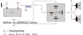
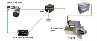
An approximate connection diagram is in the attached file (copied from www.niva.faq.msk.ru). The contact labels on the relay correspond to the figure.
In relation to YBR: Remove the wires from the standard horn. The pink one goes to the signal button (-), the brown one goes to the battery (+). In the standard circuit, the signal is constantly powered (even when the ignition is turned off), which is not a buzz at all in our humid climatic conditions.
Connect the pink wire to the contact 85
relay, brown on pin
86
.
Now, when you press the signal button, a click is heard - the relay closes contacts 30
and
87
.
We strip the brown wire and attach a short wire to it. We connect it to the contact 30
.
Now (+) is constantly supplied to pins 86
and
30
.
We take 2 long wires. We connect one to pin 87
, the second to the nearest (-). In this case, I simply stripped the pink wire and connected the second wire to it. We put these wires on the contacts of the horn. Everything is ready, you can scare the neighbors /images/smilies/wink.gif
Now about the placement. I screwed the relay in place of the standard signal (it has an eyelet, just under the standard nut). The sound signal itself was attached to the left under the decorative air intake (where it is installed on the European version), under a standard mount. I used the brackets that came with the kit (I just bent them 90 degrees at the top).
To publish messages, create an account or log in
In most cases, they are single-tone and very quiet, and their sound can scare away only a sparrow, and not attract the attention of other road users.
We isolate everything securely. There are even ready-made blocks for relays with wires. Therefore, I decided to install a signal from GAZ.
In most cases, they are single-tone and very quiet, and their sound can scare away only a sparrow, and not attract the attention of other road users. If this is important to you, then you can install another relay at the battery that will turn on the power when you turn on the ignition, or install a signal control relay next to the battery and the power wire will be as short as possible.
Watch the video
Connecting a signal through a relay immediately solves many problems, the main one of which is electrolysis of wires due to unfavorable operating conditions of the vehicle (dirt, moisture).
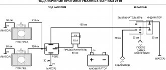
Step-by-step installation process
Before starting work, it is advisable to print out a detailed wiring diagram linked to your car: with color-coded wires and power connection points. It is necessary to mark the contacts, otherwise errors during assembly may occur. The diagram adds relay No. 4 with a button to turn on the pneumatic signal and a front parking sensor switch.
Important! External connections may vary depending on the vehicle brand.
1. We carry out the wiring of wires and connectors for the relay according to the diagram.
2. Wires will inevitably cross each other; if the insulation is good, this is not a problem.
3. Contacts are crimped mechanically; a soldering iron is not used.
4. After connecting all the wires, we form bundles and place them in the corrugation.
5. To connect control and power wires, it is convenient to use a ready-made connector: in this case, from the steering column switch of a classic VAZ.
6. If the relay unit is installed under the hood, it must be covered with a standard cover. This is not necessary for salon installation.
How to connect an audio signal
Having collected all the necessary elements, only now can you move on to the most important action - connection.
- The first step is how to connect a signal through a relay: remove the “-” terminal from the battery.
- Next, you need to remove the sound signal and install a relay in its place.
- Wire connection options
- A so-called “leech” is installed on the “+” wire that connected the sound signal. A wire approximately 15 cm long with male-female terminals is connected to it;
- If it is not possible to install a “leech”, you can strip the positive wire, then solder a piece of wire with a “mother” terminal to it. The soldering area must be sealed with insulating tape or pre-applied heat shrink.
- Next, the “+” wire must be connected to the relay. To do this, a wire with a newly formed process is connected to the 86th and 30th contacts.
- Let's move on, figuring out how to connect a signal to a VAZ or any other car. Now you need to connect the remaining negative wire to the relay. To do this, you need to use pin 85.
- An audio signal is connected to the remaining 87th contact of the relay.
- Last step: put the “-” on the battery.
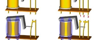
First, let's look at the diagram
The operating algorithm is as follows: when starting the engine, the daytime running lights should light up and the recorder should turn on. After turning off the engine, these devices turn off. In addition, the DRLs must go out when the side lights or headlights are turned on: this is required by technical regulations.
For implementation, you will need three standard 5-pin automotive relays (sold in a car store). In the diagram they are indicated by numbers 1, 2 and 3.
1. Green wire – power supply. 12 volts through a fuse are constantly supplied to contacts No. 87 (normally open) of relays 1 and 3. Output contacts No. 30 are connected to the positive inputs of the recorder and the running light module. The negative wire (ground) can be connected to the car body at the location where the devices are installed.
2. The red wire in the diagram supplies the control voltage of 12 volts, which appears after the engine starts (or turns the ignition key). In automotive circuits it is designated as “HOT RUN”. There are quite a lot of connection points: from the radio to the power supply to the fuel pump. The signal is easy to find in the description of your car.
3. When 12 volts appears on the red wire (contact No. 85), relay coils 1 and 3 are activated, the supply voltage through the green wire is turned on by the recorder and DRL (contacts No. 87 and No. 30 are closed).
4. On relay 3, control voltage is supplied through normally closed contacts No. 87a and No. 30 of relay 2. When voltage is applied to contact No. 85 of relay 2, the coil is activated and stops supplying control voltage to relay 3. The control signal comes from the side lights being turned on: The DRL goes out, but the recorder (via relay 1) continues to work.
Air signal connection
If you need to connect not an electric, but an airborne sound signal, the connection procedure will be almost the same as described above. The difference is that the wire from the relay does not go to the sound signal itself, but to the compressor (the engine that supplies air to the signal). And the pneumatic signal pipes are connected to the compressor through tubes.
When you press the horn, air from the compressor is supplied to the horns. With the help of a membrane installed in them, a sound signal is obtained.
You can read about how to connect the headlights yourself in our article How to connect the headlights.
Why do you need a relay?
The seller persistently sold me a relay for 40 rubles, saying that I couldn’t do without this device. But in the end it worked out without him.
What is the point of a relay?
First version (myth). The bottom line is that the VAZ and Volgov circuits for connecting sound signals are not the same. The horns on the Volga take the ground from the body, and on the VAZ - from the connected wire. According to the sellers, when we press the beep, we close the ground (-), not (+). Therefore, if you connect without a relay, the horn will work constantly. But in reality, everything turned out quite the opposite, which made the work easier. Therefore, we proceed as follows.
Second version (more real). Signals for the Volga consume a current of 14 A, and a standard beep 5.5 A. Due to excessive load, the fuse may melt, and if you set its rating higher, the tracks on the board will melt.
If you want to install a relay, install it, but I don’t care, because the loads going to the horn are not constant, but short-term.
What to pay attention to
Connection via relay 4-pin connection diagram
Although there are no requirements in GOST (except perhaps a fine for the absence of a signal), it is important to remember that high-frequency beeps are standardized, so make sure that the main frequency remains unchanged. In addition, you should not choose horns that imitate a steam locomotive or other vehicles that a pedestrian or motorist in the oncoming traffic simply does not expect to hear
Think about your health, as doctors do not recommend using signals with a frequency of more than 440 Hz. If you are planning to purchase a powerful multi-voice horn, then do not forget to take care of high-quality sound insulation in the car
In addition, pay attention to the following nuances:
- Before purchasing, you should make sure that the vehicle battery will “pull” the selected horn. If you plan to combine several beeps, the battery will discharge very quickly, since such “toys” are voracious and consume about 20-25 A.
- When choosing a horn, check with the seller whether you will need to connect the horn to power or whether you will need to purchase a compressor (which may be included) for operation.
- If you need more bass in the horn, then choose low-frequency models, and vice versa, for a subtle sound, high frequencies are better suited. For a polyphonic melody, both are used.
- Remember that voltage is different in cars and trucks. For cars it is 12 V, and for trucks it is 24 V.
Instructions for installing an alarm device
Installing this system on your car is carried out in several basic steps.
- First you need to find a place for the compressor. This may not be so simple. Most cars have a space under the bumper where you can place it.
- Remove the compressor from the frame, it is not needed and interferes with installation.
- The pipes can be installed on the radiator cooling system. They and other elements should not interfere with the heat transfer of all elements of the car.
- Now lay the pipes, fittings and valves. To connect the threads of pneumatic tubes, you can use FUM tape.
- Take the wires from the standard power button into the interior.
- Now you need to connect the system to the battery. It is best to do this through an additional relay, so that power is supplied only after the car is ignited.
- Lay air lines up to the air signal.
- You can make a connection through a relay, which will close the contacts of the system toggle switch and control it. It will also be activated from the standard button on the steering wheel.
- Before assembling the car body, check how everything works. Place the air intake fittings higher in the engine compartment. Check how the pressure is maintained.
Removing the Frame from the Compressor
Remember that you can always remove the air hose. It is long enough that you can use it to inflate the tires of any wheel. This is an additional advantage of installing such a signal.
Price issue
Characteristics of the pneumatic signal
Before moving on to how to make this device with your own hands, you need to understand what a pneumatic signal is. And also, what is its operating principle, what are its functions, design. And of course, the pros and cons of having such a horn on board your car.
Working principle and functions
The operating principle of the device is quite simple. Pressurized air from the compressor moves through the tube. This causes it to vibrate and make sounds of a certain frequency. Due to the certain complexity of the design, the cost of such a device is quite high . If you decide to assemble and install it yourself, you will save some money, but the costs will still be significant.
There are signals with different pipe shapes, as well as signal power, which can reach up to 125 dB (video author – Varan Varan).
Design
This device consists of the compressor itself and a tube. The number of the latter can reach up to three. The increased number of horns allows you to achieve a richer and more powerful sound. However, even with one tube, the pneumatic type signal makes a powerful impression. The design also includes a solenoid valve, a check valve, a pressure switch and a receiver.
Types of car horns
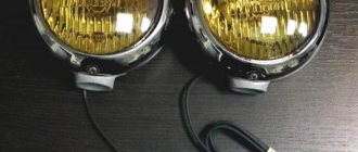
Pneumatic signals
They work on the same principle as the old horns from the days of horse-drawn carriages: a compressor supplies compressed air through a pipe, causing vibrations. All copies are in the same price category, while differing in design. Most often this concerns the shape of the horn pipe.
Pneumatic signals can have a power of up to 125 dB, and their frequency range is located at several required levels at once. This is achieved by placing four “horns” (in some cases less). Thus, the lowest signal plays at a frequency of 320–415 Hz, and the highest sound can reach up to 810 Hz. To power this orchestra, the compressor needs a pressure of at least six atmospheres. In this case, the sound of the horn will form a real melody, but this requires programming the device and a lot of space under the hood.
Electromagnetic beeps
In such equipment, the main element is an electric magnet, which is connected to the membrane. The breaker connects the current source to the core winding, and it, in turn, to ground using a signal button. Activation of the latter causes the core rod to perform oscillatory movements, which lead to vibration of the membrane. These signals differ according to the criterion of the sound emitter.
Disc horns
They have a collapsible or one-piece design. The latter allow you to save several centimeters of space. The type of execution allows you to install open and closed, respectively, in plain sight or under the hood. Standard signals are designed in a similar way, which allows you to install “pancakes” without much effort. The device can be two-tone, but single-tone ones can also be configured by combination, resulting in a synthesis of a high-frequency signal (420–440 Hz) and a simple one (335–350 Hz).
This type is more difficult to install due to the curved shape of the pipe and larger size. Signal power - 118 dB, frequency - 510 Hz. These kind of gramophones are known for putting a lot of pressure on the eardrums. A two-tone "snail" may have a relay that supplies electricity alternately to each of the windings, allowing it to produce a melody.
Relay connection diagram: contact, 12V, intermediate, operating principle and control
A relay is a system of switches necessary for switching, disconnecting and connecting electrical circuits. The purpose of operating a switching device is to create specific operating conditions for the equipment. Connecting a relay means creating a load on the switch that controls the device.
Relay Mechanisms
Basic elements of an electromagnetic relay
The relay device is made in the form of a coil wrapped in a large amount of copper wire. Inside it there is a core-rod made of metal, fixed on a yoke - an L-shaped plate. On top of the core and coil is an armature - a metal plate that is held in place by the return spring. Movable contacts are attached to the armature, and fixed ones opposite them.
The assembly of the coil and the core is an electromagnet, and the assembly of the core, armature and brightness is the magnetic circuit. The contacts provide control of the electrical circuit, opening and closing it.
Principle of operation
Operating principle of electromagnetic relays
The principle of operation of a 4-pin or 12-volt model relay is similar. Without applying voltage to the device, the armature is removed from the core using a return spring.
At the moment when voltage is applied, a current begins to move through the winding, the magnetic field of which acts on the core. The magnetized element, by overcoming the forces of the return spring, attracts the armature. Its active contacts move, opening or closing with stationary ones.
After the voltage supply is stopped, the winding current disappears and the core is demagnetized. The return spring returns the armature and contacts to their original state.
Types of relays
Single-phase digital voltage monitoring relay for DIN rail
Relay devices are classified according to several parameters.
Number of phases
Divided into:
- single-phase - designed to supply voltage in residential premises;
- three-phase – suitable for use in industrial environments.
Three-phase switches turn off the power to all equipment when voltage surges on one of the lines.
Switching type
Models available for purchase:
- maximum – increase the voltage parameter to a certain value;
- minimum – reduce the indicator to a specified value.
The voltage threshold is not set by the user.
Type of activation of the perceptive element
Intermediate relay RP-18-54 220V DC
The sensing element, upon activation of which the device will operate, is an electromagnet, magnetoelectric unit, induction or electrodynamic system. Depending on its type, there are relays:
- primary with direct connection of contacts to the network;
- secondary - can be connected through measuring inductive or capacitive transformers;
- intermediate – amplify or convert signals of primary/secondary models.
The functions of the sensing element are the transformation of voltage into the process of movement of the armature relative to the yoke.
To publish messages, create an account or log in
In most cases, they are single-tone and very quiet, and their sound can scare away only a sparrow, and not attract the attention of other road users.
We isolate everything securely. There are even ready-made blocks for relays with wires. Therefore, I decided to install a signal from GAZ.
In most cases, they are single-tone and very quiet, and their sound can scare away only a sparrow, and not attract the attention of other road users. If this is important to you, then you can install another relay at the battery that will turn on the power when you turn on the ignition, or install a signal control relay next to the battery and the power wire will be as short as possible.