Tools and preparatory work
To adjust the valves, the Niva must be placed on a level surface. Work can be carried out both in the garage and outdoors; you can drive onto an overpass, but this is not necessary.
Tools and materials
From a special tool, which perhaps not every motorist has, you will need a probe 0.15 mm thick. Its width must be sufficient to be used for adjusting the intake valves. A feeler gauge with a thickness of 0.2 mm is also required. It is used to adjust the exhaust valve.
To work you need to have the following tools and materials:
- Open-end wrenches 17, 13, 8;
- Ratchet (spanner with ratchet and replaceable heads);
- Socket wrenches for 8 and 10;
- Candle key;
- Crankshaft key;
- Screwdriver;
- Rag, rags – clean;
- Brush.
A magnet on a telescopic holder is also useful for detecting and removing fallen fasteners. Almost all the tools - except for keys 13 and 17, as well as probes - are needed for disassembly in order to gain access to adjustable parts.
Preliminary preparation
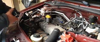
First of all, you need to disconnect the battery. Next you will need to disconnect the air filter. To do this, you need to disconnect the crankcase gas hose from it. Then they begin to dismantle the filter housing cover by unfastening the four latches.
Now, to remove the cover, all that remains is to unscrew the 10-point nut, which is installed on the stud in the middle of the assembly. The filter housing is held in place with four 8mm nuts; they are easiest to remove with a spanner. Finally, you need to cover the carburetor with a technological cover (you can make it yourself from cardboard or plywood) to prevent dirt from getting inside it.
Next you should disconnect from the carburetor:
- Longitudinal thrust. It is disconnected by removing the mounting bracket from the return spring lever;
- Transverse traction. It is located on the throttle valve drive lever;
- Choke cable;
- Crankcase gas exhaust hose;
- Fuel line.
Continuing disassembly should begin by detaching the brake hose from the vacuum booster. Then the high-voltage wires are disconnected from the spark plugs and ignition coil. Remove the distributor sensor cover together with all wires. The spark plugs are unscrewed. Pull out the oil dipstick.
Gaining access to valves
To begin adjusting the clearances, you need to remove the valve cover. It is held in place by eight 10mm nuts. After tightening them, you need to remove all the brackets and pressure washers.
Step-by-step instructions with photos.
When the tools are ready and the engine has cooled down, you can start working.
The procedure is as follows:
➥Disconnect the negative terminal from the battery - almost any repair of the power plant and car electronics begins with this procedure. ➥Now remove the cylinder head cover. After this, the cap can be removed from the distributor. All fresh ignition plugs must be removed, following the order in the manual. ➥Once you have access to the crankshaft, it must be turned slowly as it rotates. Carry out this step until the marks on the bearing housing and the camshaft drive sprocket line up. ➥Install the desired wrench on the ratchet and rotate the shaft with both hands.
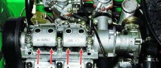
➥The marks are set, now we move on to adjusting the 6th and 8th valves (the order is from the right). A feeler gauge with a thickness of 0.2 mm must be placed between the rocker and the camshaft cam, as shown in the photo:
➥When the gap is set correctly, the feeler gauge enters with little force. To begin the adjustment, you need to loosen the locknut with the 17th wrench. Changing the distance between parts is done with the 13th key.
➥After these manipulations, check the gap again. If it corresponds to the standard, then fix the adjusting bolt and tighten the lock nut.
Carburetor repair for dips and jerks
Carburetor repair may be necessary if the engine idles unstable, and adjusting the quantity and quality screws does not always help. Often the reason lies in over-enrichment of the mixture, which may be a consequence of incorrect adjustment of the float system or malfunctions in the vacuum economizer system for power modes. In the latter case, a torn diaphragm may need to be replaced or the economizer valve through which fuel is leaking may need to be repaired.
Model 2121 may cause jerking, swaying or dips when moving. In this case, there may be several reasons for their occurrence, which may require carburetor repair to eliminate them. Dips that appear when the throttle valve is slowly opened are often associated with clogging of the idle jet. Here it is necessary to adjust the fuel level and check the level of clogging in the main fuel jets.
If the car gives a deep failure when trying to open the first or second throttle chambers, then in addition to clogged nozzles, the reason may be poor installation of small diffusers in the corresponding sockets.
When the Niva 21213 gives slight twitches at low and medium speeds and accelerates sluggishly, it may be due to poor fuel dosage on the shut-off valve side due to its wear. In this case, repairs are needed in terms of replacing the shut-off valve with a shut-off needle made of metal with a valve that has this needle made of a different material.
All-terrain vehicles VAZ 2121 "Niva" already have reliable and durable equipment from the factory. The Niva uses a carburetor engine as its power unit, which allows for uninterrupted loads under any operating conditions. Repairing and adjusting the carburetor on a VAZ 2121 is a much simpler matter than it might seem at first.
What kind of carburetor is installed on the Niva initially?
The Niva car is equipped with carburetors from the classic “Ozone”, which is not the best two-chamber unit with an idle economizer. The economizer is an autonomous system with a solenoid valve that automatically comes into operation when the ignition is turned on. When gaining speed above
1000, it is turned off, and the engine is maintained using the air damper.
The updated model received the French Solex design. The 1.7-liter engine required an increase in the amount of air-fuel mixture, and therefore Ozone was no longer used.
To reduce the cost of the project, it was decided to use parts and assemblies used on other engines that were in serial production at the time of 1994.
So the cylinder block was taken from the 03 Zhiguli model. The height of block 03 is 214.58 millimeters. The distance between the centers of the cylinders is 95 millimeters. Cylinders have five classes, designated by Latin symbols. The corresponding marking is located at the bottom of each cylinder.
A new piston group was developed for the new engine. The Model 213 piston has a unique design. At the bottom there is an oval hole of a specific shape. The piston diameter size has five classes. The hole for the piston pin has a diameter of 22 mm. Finger length 67 mm. Finger installation design, floating. The pin moves freely in the connecting rod head and piston bosses. Locking rings protect against axial displacement of the pin. The piston marking by bore diameter and piston diameter is applied to the bottom of the piston. The piston weighs 0.347 kg.
Connecting rod 213 is a new design model. It has a length of 136 mm. The hole for the crankpin is 47.8 mm. The diameter of the hole for the piston pin is 22 mm. For the connecting rod cap, designed new, disposable bolts. Reuse of bolts is prohibited.
The crankshaft is based on a VAZ 2103 crankshaft, the crank mechanism has a radius of 40 mm. For better dynamics and vibration prevention, the crankshaft is equipped with additional counterweights. For improved lubrication, oil lines were drilled into the connecting rod journals, and their diameters were increased by 0.02 millimeters.
The BC head is taken from the 011 Zhiguli model. The combustion chambers have undergone changes, they have been increased to 30 cubic centimeters each.
The timing chain drive is made with a double-row roller chain taken from the 03 model.
For the new engine, a new camshaft 21213-1006010 was designed. The shape of the cams on it was changed; this had to be done to increase the intake valve stroke. The valve mechanism and valves are borrowed from the VAZ 2101.
The VAZ 21213 uses a contactless ignition system with a switch, coil and ignition distributor.
An improved lubrication system has plugs for the accumulation and subsequent removal of dirt.
Cooling system diagram
Do-it-yourself Niva valve adjustment: 3 comments
I read and I feel sad. Why do people write how to do, in principle, simple things, but at the same time make mistakes that can, at best, negate all their work, and at worst lead to expensive repairs. This is not advice from your neighbor in Uncle Kolya’s garage, this is an article claiming to be a technically competent guide to action. People, read books by famous authors if you want to do something with your own hands. SPECIAL probes are used to adjust the valves; this is quite easy to know if you don’t want to think about the question “why”. The special feeler gauge has a width exceeding the width of the friction pair, which guarantees that the required gap is set over the entire width of the contact between the rocker and the camshaft cam. If, as recommended by the author, you use a conventional (narrow) set of feeler gauges, then you will not have any confidence that the rocker is level, and the gap you measured is not the gap on one side of the rocker-cam contact, while on the other side of the gap at this moment may not exist at all.
There is an error in the text. For INTAKE valves the clearance is 0.15 according to the book, and for EXHAUST valves it is 0.2
Question answer
How often are the Niva valves adjusted? I recommend carrying out the second adjustment, which I call final, after 500-700 km, after installing the kit and the first adjustment. As a rule, 2-3 valves “run away”. According to Soviet books and training manuals, it was recommended to CHECK the gaps once every 12-20 thousand km, that is, about once a year. Operational practice has shown that engines run without adjustment for 50 and 80 thousand km. Therefore, the following recommendation is factual.
A series of articles devoted to hydraulic compensators and bolts:
Part 4. Installing the “death to hydraulics” kit and adjusting the gaps
Adjust the clearances on a cold engine by first adjusting the chain tension. After adjustment, the gap should be 0.15±0.02 mm for the intake valves and 0.2±0.02 for the exhaust valves.
During adjustment, make sure that the valve lever is not installed askew, as this may lead to an overestimation of the actual clearance.
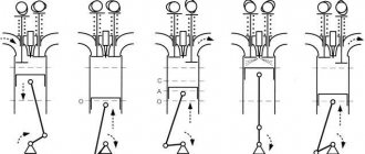
Make adjustments in the following order:
- Turn the crankshaft clockwise until the mark on the camshaft sprocket aligns with the mark on the bearing housing, which will correspond to the end of the compression stroke in the fourth cylinder. In this position, the clearance at the exhaust valve of the 4th cylinder (8th cam) and the intake valve of the 3rd cylinder (6th cam) is adjusted;
- loosen the lever adjusting bolt nut;
- insert between the lever and the camshaft cam a flat feeler gauge A.95111 with a thickness of 0.15 mm for the intake valve (0.2 mm for the exhaust valve) and a wrench, tighten or unscrew the bolt by then tightening the lock nut until, with the lock nut tightened, the feeler gauge enters with ease pinching (Fig. 2-42);
- After adjusting the clearance of the exhaust valve of the 4th cylinder and the intake valve of the 3rd cylinder, turn the crankshaft 180° in sequence and adjust the clearances in the order shown in Table 2-2.
How to adjust Ozone
Self-adjustment of the Ozone carburetor on a VAZ 2121 car allows you to achieve stable operation of the power unit and reduce gasoline consumption.
Typically, adjustment work includes adjusting the starting unit, the idle speed unit and the fuel level in the float chamber tank. To quickly carry out the work, it is recommended to immediately prepare the following set of tools:
multimeter (or tachometer);
flat narrow screwdriver.
The procedure for performing adjustment work:
It is necessary to warm up the engine to its operating temperature.
With the engine running, you will need to fully open the air damper of the carburetor mechanism - fully press the damper drive handle (that is, the choke).
Connect the tachometer (multimeter) to the engine: the minus wire to the vehicle ground, the plus wire to the ignition coil to terminal K.
After connecting, you need to start the engine again, immediately turn on the lighting and the fan to supply heat.
Use a screwdriver to start adjusting the air-fuel mixture supply screw - you need to turn the screw until the power unit begins to idle smoothly. The optimal tachometer indicator is 750–800 rpm.
If it is not possible to achieve the desired performance by normal adjustment, you will need to remove the carburetor and thoroughly rinse it from dirt deposits. Apparently, the mechanism is so clogged with sediment coming from the fuel that its adjustment is impossible.
Video: do-it-yourself carburetor adjustment on a Niva
By adjusting or repairing the carburetor with your own hands, the car owner can be confident in the high quality of the work. In addition, a visual inspection of the internal components of the unit will allow you to draw a conclusion about its resource and thus calculate the frequency of maintenance or routine cleaning. Ozone carburetors have been an invariable attribute of Niva cars for many years, ensuring reliable engine operation and excellent operating characteristics.
How to adjust valves on a VAZ 21213
After a certain period has passed, the valves must be adjusted for each car.
In this material we will analyze in detail how this procedure is performed, what tools are needed for this, and what you should pay attention to when adjusting Niva valves. This instruction is relevant for the following Niva models: 21213, 21214, 2121. Adjustment of Niva valves is required for the power plant to operate in normal mode. Our task is to maintain the gap between the valves set by the manufacturer.
If the distance between the parts exceeds the permissible norm, the driver hears unpleasant noises made by the car engine.
When the valves are too tight, the power plant cannot produce maximum power, dynamics suffer and fuel consumption increases. You can find out how often this procedure needs to be carried out in the car’s operating manual; the procedure is also indicated there.
As the experience of owners of domestic models of this brand shows, correct valve adjustment is enough for 20 thousand kilometers. Determining that the gaps need adjustment is quite simple: grinding, clattering and other noises appear, which become especially loud at medium and low speeds.
3.4 Adjusting thermal clearances in the valve mechanism of a carburetor engine
Service and operation
Manuals → VAZ → 21213 (Niva)
Adjusting thermal clearances in the valve mechanism of a carburetor engine
| In this case, the mark on the crankshaft pulley should be located opposite the TDC (long) mark on the camshaft drive cover. |
In this position of the shafts, corresponding to the end of the compression stroke in the 4th cylinder, we check and, if necessary, adjust the clearances at the exhaust valve of the 4th cylinder (8th cam) and the intake valve of the 3rd cylinder (6th cam). Sequentially turning the engine crankshaft 180 clockwise, we check and adjust the clearances of the remaining valves in the order shown in the table:
| Angle of rotation of the crankshaft, degrees. | u0004 adjustable valves (cams) |
| 8 and 6 | |
| 180 | 4 and 7 |
| 360 | 1 and 3 |
| 540 | 5 and 2 |
| The angle of rotation of the crankshaft can also be controlled by the distributor slider. When the crankshaft is turned 180, the slider will turn 90. |
| To check the gap, insert a wide flat feeler gauge 0.15 mm thick for the intake valve or 0.20 mm for the exhaust valve between the valve lever and the camshaft cam. |
With a normal gap, the dipstick should enter with a slight bite.
| To adjust the gap, use a wrench u0016 to 17u0006 to loosen the lock nut of the adjusting bolt, and use a wrench u0016 to 13u0006 to rotate the adjusting bolt, setting the required gap. |
Tighten the locknut while holding the adjusting bolt from turning. We check the gap again and, if necessary, repeat the adjustment. You can adjust the clearance in the valve mechanism using a device with an indicator. For this…
| ...install the device bar on the camshaft bearing housing... |
| ...and fasten the bar to the body mounting studs. |
| We install the stand with the indicator on the device bar opposite the valve being tested,... |
| ... resting the protrusion of the indicator post rocker arm on the back of the valve lever. |
We fix the indicator stand on the bar. Having rested the indicator leg against another protrusion of the strut rocker arm,...
| ...we fix the indicator on the stand. |
| By lifting the valve lever with the fork plate of the device, we determine the gap in the valve mechanism using the indicator in accordance with the instructions for the device. |
| If necessary, adjust the gap. |
automn.ru
How to adjust VAZ 21213 valves
If you need instructions on “adjusting VAZ 21213 valves,” then this material will be quite useful to you.
So, how is the VAZ 21213 valves adjusted? Clearances are checked and adjusted on a cold engine. For intake valves, the gap should be 0.15 millimeters, and for exhaust valves - 0.2 millimeters. There is no need to memorize the exhaust and intake valve numbers; all you need to do is look at the corresponding manifolds. Opposite the intake manifold pipes are the intake valves, and opposite the exhaust pipes are the exhaust valves.
The gap must be set as accurately as possible. With a large gap, there will be greater wear on the rocker, valve end and camshaft cam, but with a small gap, the valve plates may burn out.
https://www.youtube.com/watch?v=I505WZuqu1k
Before you begin adjusting the VAZ 21213 valves, you need to check the fastening of the camshaft bearing housing, tension the chain, and align the marks on the crankshaft pulley with the camshaft sprockets. The adjustment itself can be done either using a probe or using a device with a micrometer. Adjustment with feeler gauges is an inaccurate and time-consuming operation; surface unevenness is not taken into account, so the gap will not be entirely accurate. Actually, for this reason, it is recommended to adjust the valves using a bar with a micrometer. With her everything will go faster, more accurately and easier. Even a beginner can handle this procedure.
—
The new IPS 111 unicycle will be an indispensable attribute of a modern person who always values speed and takes care of the environment. Long range, attractive design, as well as small size make the IPS 111 model optimal for daily use in everyday life.
Adjusting valves on a VAZ-2101-07 – video bonus
(2 votes, average: 3.00 5) Loading …
avtogury.ru
Do-it-yourself valve clearance adjustment
Every experienced Niva car owner probably had to independently perform such a procedure as adjusting the thermal valve clearances. The quality of this procedure directly determines how well the engine of your car will work. After all, if the gap is less than required, then, of course, the valves will be clamped and the engine will not develop maximum power, and this will affect the dynamic characteristics of the car. On the other hand, if the gap, on the contrary, is larger than permissible, then a rather unpleasant knock will be heard when the Niva’s internal combustion engine is operating.
To carry out this procedure yourself, you will not need many tools. I will list everything you need below:
- Open-end wrenches for 17 and 13
- Set of styli or one stylus 0.15 mm thick
Instructions for adjusting valves on Niva
Please note that this procedure is performed only on a cold engine, that is, its approximate temperature should be about 20 degrees.
The first step is to remove the valve cover from the engine. After this, you will need to align the crankshaft and camshaft to the marks so that the 4th cylinder is at top dead center. To do this, combine the mark on the crankshaft pulley with the central mark on the front engine cover. For clarity, all this is shown in the photo below:
You can rotate the shaft either using a suitable wrench using the ratchet, with both hands, grasping it tightly (with the spark plugs unscrewed). We set the position of the camshaft in the same way so that the mark on the sprocket aligns with the protrusion on the body:
After the marks are set, you can begin to adjust the 6th and 8th valves (counting is done from left to right). To do this, take a 0.15 mm feeler gauge and insert it between the camshaft cam and the rocker. It roughly looks like what is shown in the picture:
Please note that the dipstick should enter with little effort. If the gap differs from the recommended one, it must be adjusted. To do this, use a 17 wrench to slightly loosen the lock nut, and use a 13 wrench to make the adjustment:
It is also worth noting that when the lock nut is finally tightened, the clearance may decrease slightly, so you should check it again after the nut is tightened.
Now a little about the order in which adjustments should be made. Below are instructions that must be strictly followed.
- So, if the crankshaft is set according to the marks, then we adjust valves 6 and 8
- We turn the crankshaft 180 degrees (half a turn) - set the gap to 4 and 7 cells.
- Full revolution - at this moment we perform the procedure with valves 1 and 3
- 540 degrees (one and a half turns) - 2 and 5 valves, respectively
To make it more convenient to count crankshaft revolutions, you can divide it with a mark, for example, draw a line in the center of the pulley with chalk or a marker. Or, instead of the crankshaft, you can count the revolutions of the distributor slider. Only there, every two subsequent valves are adjusted after 90 degrees of rotation.
On injection systems, this type of maintenance is performed in almost the same way, and in general, following this guide, you can do everything without straining.
niva-remont.com
Source: https://autoprivat.ru/remont_avto/kak_otregulirovat_klapana_na_vaz_21213.html
Re: valve adjustment
Post by Captain » 06 Dec 2010, 04:50
Do-it-yourself adjustment of VAZ 21213 valves
Niva is an all-wheel drive vehicle that has received recognition not only at home, but also abroad. This is a reliable, unpretentious car, the self-repair of which is accessible to most car enthusiasts. Therefore, preventive measures can be carried out in a timely manner without unnecessary costs. Adjusting the valves on a VAZ 21213 with a carburetor engine can be done with your own hands and will not require excessive labor costs or special skills.
Carburetor Niva 21213: diagram, adjustment, tuning, repair
Niva carburetor: we set up and repair it ourselves
The carburetor on models 2121, 21213 and other cars has basically the same device. Functionally, it is located in the propulsion system, and with its help the fuel is mixed to the state of a combustible mixture. A carburetor, as a rule, consists of several main elements - a float chamber, a so-called jet (with a spray), a diffuser, and a throttle valve. It can have from one to four cameras on different cars, sequential or simultaneous opening of the throttle valves, horizontal, downward or upward movement of the working mixture.
Design features of the VAZ 21213
The appearance of pistons with a diameter of 82 mm in the arsenal of AvtoVAZ engineers allowed them to finally begin creating a more powerful engine for the Niva. The 1.6-liter 2121 engine was taken as the basis, but with a lower block height. An increase in the cylinder diameter by 3 mm gave an increase in working volume by 100 cubic meters and torque by 10 Nm.
Among the other innovations, we note:
- a Solex-type carburetor finally replaced the outdated Ozone;
- a modern contactless ignition system has appeared;
- original pistons with part of the combustion chamber in the bottom;
- new crankshaft with eight counterweights;
- cooling system with an aluminum radiator instead of a brass one.
With the help of simple modifications you can increase the volume to 1.8 liters.
Similar engines from other manufacturers:
Characteristics of motor 21214
Recommended fuel consumption standards for 2022 It is believed that the basis of the ICE 21214 was the previous version 21213. In fact, ¾ of the parts in the engine
- the engine layout has changed - an injector instead of a carburetor;
- additional attachments appeared - DPKV, DXX sensor, Bosch MP 7.0 controller;
- crankshaft with a long crank radius of 40 mm, not used in previous AvtoVAZ engines;
- Cylinder head with holes for phase sensor and receiver studs, hydraulic supports for valve levers instead of adjusting bolts.
Hydraulic mounts
cylinder head 21214
The design of the power drive 21214 provides it with the following technical characteristics:
| Manufacturer | AvtoVAZ |
| Engine brand | 21214 |
| Years of production | 1994 – … |
| Volume | 1690 cm3 (1.7 l) |
| Power | 59.5 kW (81 hp) |
| Torque moment | 127.5 Nm (at 4000 rpm) |
| Weight | 122 kg |
| Compression ratio | 9,3 |
| Nutrition | injector |
| Motor type | in-line |
| Injection | distributed electronically controlled |
| Ignition | modular |
| Number of cylinders | 4 |
| Location of the first cylinder | TVE |
| Number of valves on each cylinder | 2 |
| Cylinder head material | aluminum alloy |
| Intake manifold | duralumin |
| An exhaust manifold | cast iron or welded steel |
| Camshaft | original cam profile |
| Cylinder block material | cast iron |
| Cylinder diameter | 82 mm |
| Pistons | from 21213 |
| Crankshaft | from 21213 |
| Piston stroke | 80 mm |
| Fuel | AI-92 |
| Environmental standards | Euro-2/3 |
| Fuel consumption | highway – 8.3 l/100 km mixed cycle 10.5 l/100 km city – 11.5 l/100 km |
| Oil consumption | maximum 0.7 l/1000 km |
| What kind of oil to pour into the engine by viscosity | 5W30, 5W40, 10W40, 15W40 |
| Which engine oil is best by manufacturer | Liqui Moly, LukOil, Rosneft, Mannol, Mobil |
| Oil for 21214 according to composition | synthetics, semi-synthetics, mineral |
| Engine oil volume | 3.75 l |
| Operating temperature | 95° |
| ICE resource | declared 80,000 km actual 160,000 km |
| Adjustment of valves | hydraulic compensators |
| Cooling system | forced, antifreeze |
| Coolant volume | 7.8 l |
| water pump | with plastic impeller |
| Candles for 21214 | BCPR6ES from NGK or domestic AU17DVRM |
| Spark plug gap | 1.1 mm |
| Timing drive | single row chain |
| Cylinder operating order | 1-3-4-2 |
| Air filter | Nitto, Knecht, Fram, WIX, Hengst |
| Oil filter | with check valve |
| Flywheel | from 21213 with clutch bore diameter 200 mm or 215 mm |
| Flywheel mounting bolts | M12x1.25 mm, length 26 mm |
| Valve stem seals | manufacturer Goetze, light inlets, dark exhausts |
| Compression | from 12 bar, difference in adjacent cylinders maximum 1 bar |
| XX speed | 800 – 850 min-1 |
| Tightening force of threaded connections | spark plug – 31 – 39 Nm flywheel – 62 – 87 Nm clutch bolt – 19 – 30 Nm bearing cap – 68 – 84 Nm (main) and 43 – 53 (rod) cylinder head – three stages 20 Nm, 69 – 85 Nm + 90° + 90° |
Is it necessary to adjust the valves on the VAZ 21214 engine?
The VAZ 21214 engine was developed by VAZ for off-road vehicles of its own production, Niva.
The design of the internal combustion engine is developed on the basis of the 21213 engine using parts and assembly units included in the 2112 specification. In modifications, individual components are taken from the 2123 engine. The internal combustion engine differs from the 21213 in the presence of: an injector (assembled); catalyst; hydraulic compensators for timing valves; power steering; engine assembly units modified for injector. The series was launched in 1994, later including modifications, and was used in the assembly of VAZ Niva (2121, 21213, 21214, 2131) and Nadezhda 2120 SUVs. Initially, the unmodified engine model had centralized fuel injection from one injector (in intake manifold) into 4 cylinders. The first modification of the 21214-10 engine received distributed injection from four individual injectors (1 per cylinder), with a Bosch MP7.0 controller and compliance with Euro 2. With the transition to Euro 3 and the installation of hydraulic compensators in the valve mechanism, it entailed further refinement of the internal combustion engine. Using certain innovations, the following subsequent modifications of the engine were produced.
Ours or not ours?
In Russia, the bulk of valves are produced by two factories: Samara (conveyor supplier) and Chelyabinsk. Samara valves have good geometry, but not the best material, Chelyabinsk valves are curved like a poker, but made of good heat-resistant steel. How I determined the quality of the material, I will tell you a little later. I won’t say it better than what the classic said: I wish I could put Ivan Ivanovich’s lips on Ivan Afanasyevich’s nose, and perhaps add to this the portliness of Ivan Andreevich, etc. - N.V.Gogol. In general, the domestic product does not fit our initial postulate about “quick and high-quality repairs.”
Self-adjustment
After the tools are prepared and the motor has cooled down, you can proceed to self-adjustment. The operating procedure will be as follows:
- Disconnect the negative terminal from the battery. This action begins all manipulations with the engine or electronics of the car.
- Next, unscrew the cylinder head cover and proceed to dismantling the distributor cover. After this, you need to unscrew the spark plugs.
- Now access to the crankshaft has opened. It must be turned slowly in the direction of rotation, until the marks located on the bearing housing and the camshaft match.
- The marks are set, and you can proceed to adjustments on the 6 and 8 m valves. A feeler with a thickness of 0.15 mm must be inserted between the camshaft cam and the rocker.
- If the job is done correctly, the probe will enter with little force. In order to begin the adjustment, you need to press out the lock nut with a wrench 17. Adjustment is carried out with key 13.
- After the adjustment is completed, you need to check everything again. If it corresponds to the standard, you can fix the adjustment bolt and tighten the lock nut.
- Next, we turn the crankshaft 180 degrees and proceed to adjust the next pairs 4 and 7, and then 1 and 3.
Why do you need to make adjustments?
Adjustment of Niva valves is required for the power plant to operate normally. Our task is to maintain the gap between the valves set by the manufacturer. If the distance between the parts exceeds the permissible norm, the driver hears unpleasant noises made by the car engine.
When the valves are too tight, the power plant cannot produce maximum power, dynamics suffer and fuel consumption increases. You can find out how often this procedure needs to be carried out in the car’s operating manual; the procedure is also indicated there.
As the experience of owners of domestic models of this brand shows, correct valve adjustment is enough for 20 thousand kilometers. Determining that the gaps need adjustment is quite simple: grinding, clattering and other noises appear, which become especially loud at medium and low speeds.
Pros and cons of ICE 21213
The VAZ 21213 engine has a number of advantages compared to earlier ICE models.
An undoubted advantage is the use of a Solex carburetor without the problem. It rarely gets capricious, and its fuel consumption is comparable to that of an injector.
This engine has improved characteristics not only of power and torque, but also of throttle response and speed.
The internal combustion engine cylinder block guarantees several repairs of the ShPG.
The advantages include simplicity of design, availability and low cost of spare parts, as well as the ability to carry out repairs on your own.
There are not many disadvantages, these are increased consumption of working fluids and poor quality of factory assembly. Other breakdowns also occur, but they do not occur often and do not spoil the engine’s reputation.
Installation in reverse order
Installing a carburetor mechanism on a Niva takes much longer than removing it. This is because the reverse process is more complex in terms of connecting hoses and fuel lines.
The procedure for installing Ozone on a VAZ 2121 is as follows:
- The device is threaded onto four studs to the intake manifold.
- The corresponding nuts are screwed onto these studs to give the carburetor stability and the required position.
- The throttle control rod snaps into place.
- The choke cable is screwed into place.
- Next, you will need to connect all the hoses in strict order: first the fuel pipe, then the return line, after which you can connect the remaining hoses in any order.
- The fuel filter box is screwed to the carburetor body.
- After this, the box is attached to the engine compartment frame.
Installing a new camshaft
The replacement process will take no more than 15 minutes; beginners may need more time. Before installation, using a syringe with fresh oil, go over the main elements of the mechanism; it will also be useful to coat the parts that will come into contact with the head with a layer of sealant.
The oil seal is put on the new camshaft and installed in place in the position in which the old one was removed. After the camshaft has been placed in its place, it is necessary, as during disassembly, to tighten the nuts evenly, crosswise. The next most important assembly step will be adjusting the valve clearances:
- For intake valves from 0.2 mm,
- For graduation from 0.3 mm.
For those who have not previously encountered adjusting valve clearances, it is strongly recommended that you familiarize yourself with this topic in more detail, since there are many methods and devices for this.
After installation and adjustment, replacing the gaskets on the cover will be beneficial. The oil seal is replaced depending on its wear. Adjust the position according to the previously set marks. After completing the replacement, do not rush to start the engine, go through all your actions in your head again, check the fastening of the main elements, the chain tension, and whether the ignition is set correctly. Sometimes it happens that beginners have to re-disassemble the distributor and adjust the ignition.
Quick replacement of the timing chain on a Chevrolet Niva
Recently, an old friend of mine came to see me in his old Chevrolet Niva with the characteristic sound of an extended chain.
In addition to the timing kit, I had the foresight to purchase even a front cover gasket, a crankshaft oil seal and a kilo of marinated meat. I could not refuse such an offer. So, Niva Chevrolet replaced the timing chain and front crankshaft oil seal.
First, let the engine cool to an acceptable temperature. Remove the pipe by unscrewing the bolt by 10 and loosening the clamps.
Next, we unscrew the eight nuts by 10 and move aside the throttle cable and all the pipes that will interfere with us, remove the valve cover.
Remove the air conditioner belt by unscrewing the bolt 13 of the tension roller.
Then loosen three 13mm nuts and one bolt of the generator belt tension roller and remove it.
Now comes the fun part. To unscrew the pulley nut, we need a 38mm socket. Since the elongated head does not fit under a regular wrench (the radiator is in the way, but we don’t want to remove it), we use a pry bar, carefully sawed off from the hub key of some large car.
Everything fits perfectly. Unscrew the nut and remove the crankshaft pulley.
Unscrew the deflection roller.
We dismantle the reinforcing plate.
We unscrew the six nuts securing the front timing chain cover to the block and the three bolts securing it to the pan and remove it.
Set the top dead center. The key on the crankshaft should align against the mark on the block.
The mark for the camshaft sprockets is against the ebb of the camshaft housing.
Next, unscrew the oil supply pipe and two nuts 10 of the chain tensioner.
The tube is secured with a hollow bolt and copper washers on both sides. Don't lose them.
Next, unscrew the tensioner shoe, damper and remove the timing chain.
Compare the new and old timing chain. It could be worse.
New timing kit.
Reinstall the chain, guide and tensioner shoe. We tighten the chain by hand and check that the marks match.
To make it convenient for us to check the marks after installing the front timing cover, we find the factory mark on the crankshaft pulley and mark it with a white marker. This mark at TDC should be opposite the center of the crankshaft sensor.
Adjusting the thermal clearances of the valves of the carburetor engine VAZ 21213, 21214 (Niva)
We measure and adjust the gaps on a cold engine.
Remove the cylinder head cover (see Replacing the cylinder head cover gasket). Remove the cover of the ignition sensor-distributor (see Removing the cover of the ignition sensor-distributor). We turn the crankshaft by the nut securing its pulley clockwise...
...until the mark (drilling) on the camshaft sprocket coincides with the protrusion on the bearing housing.
In this case, the mark on the crankshaft pulley should be located opposite the TDC (long) mark on the camshaft drive cover.
In this position of the shafts, corresponding to the end of the compression stroke in the 4th cylinder, we check and, if necessary, adjust the clearances at the exhaust valve of the 4th cylinder (8th cam) and the intake valve of the 3rd cylinder (6th cam). Consistently turning the engine crankshaft 180° clockwise, we check and adjust the clearances of the remaining valves in the order shown in the table:
Angle of rotation of the crankshaft, degrees.
No. of adjustable valves (cams)
The angle of rotation of the crankshaft can also be controlled by the distributor slider. When the crankshaft is rotated 180°, the slider will rotate 90°.
To check the gap, insert a wide flat feeler gauge 0.15 mm thick for the intake valve or 0.20 mm for the exhaust valve between the valve lever and the camshaft cam.
With a normal gap, the dipstick should enter with a slight bite.
To adjust the gap, use a 17 wrench to loosen the locknut of the adjusting bolt, and use a 13 wrench to rotate the adjusting bolt, setting the required gap.
Tighten the locknut while holding the adjusting bolt from turning. We check the gap again and, if necessary, repeat the adjustment. You can adjust the clearance in the valve mechanism using a device with an indicator. For this…
...install the device bar on the camshaft bearing housing...
...and fasten the bar to the body mounting studs.
We install the stand with the indicator on the fixture bar opposite the valve being tested.
... resting the protrusion of the indicator post rocker arm on the back of the valve lever.
We fix the indicator stand on the bar. Having rested the indicator leg against another protrusion of the strut rocker arm,...
...we fix the indicator on the stand.
By lifting the valve lever with the fork plate of the device, we determine the gap in the valve mechanism using the indicator in accordance with the instructions for the device.
Source
Tool
There are two ways to adjust according to the type of tool. By probes and by a dial indicator. For semi-professional use, the first option is suitable. The Fiat manual recommended the following clearances at an engine temperature of 20 degrees (that is, normal). Intake valves 0.15 mm. Graduation is slightly more than 0.17-0.20 mm. My personal opinion after 20 years of practice is the following. The set gap greatly depends on the manufacturer and valve material. If this is a valve of average quality, then the gaps can be made according to the manual. If there are Kolbenschmidt valves on both the inlet and outlet, then you can do 0.15 in a circle. Now on to the probes. Of course, everything is determined by the word experience, and the first two or three times you can adjust this... “what you can’t say in a fairy tale, you can’t describe with a pen.” Therefore, I remembered one wonderful thing for mechanics, turners and milling operators, which was made in the USSR, for technical control. It was called a plug gauge. That is, it is a calibrated tool, with two “tails”, one passable, the other non-passable. By analogy with this miracle, I offer two tools. The first is a 0.15 mm gap adjustment gauge and a set of gauges that contains a 0.2 mm gauge. Now all the “miracles” of adjustment come down to a simple thing. One should get through, the other shouldn't. This way we get into the required tolerance range.
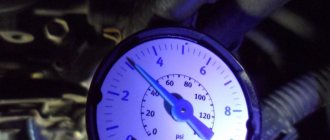
Final clearance check.
Remember that intake valves use a 0.15mm feeler gauge and exhaust valves use a 0.20mm feeler gauge. Place the tool between the camshaft cam and the lever. If you need to apply force to move the feeler gauge between parts, then the gaps are set correctly.
Re-adjustment should be carried out if the tool moves too freely or does not fit into the hole at all. When tightening the locknut, the gap becomes a little loose, so ideally the adjustment should be carried out twice, following the order indicated in the table.
The engine receives too much gasoline - the carburetor is flooded / the needle is stuck
If a car owner notices that the carburetor is constantly being filled with excess gasoline, we can conclude that the needle valve is faulty. Over time, it can lose its throughput, which is why at first there are difficulties in starting the engine, fuel drips appear on the carburetor, and then it will be impossible to start the engine at all.
Also interesting: Chevrolet Niva air conditioning - design and repair "
The way out of the situation is to replace the needle valve yourself. To do this you will need:
- Remove the cap from the carburetor.
- Align the float along its original axis.
- Disconnect the needle valve.
- Screw a new valve into the vacant space.
- Screw the lid into place.
Adjusting the fuel level in the float chamber
Performed when replacing a needle valve or float. Remove the carburetor cover (see Disassembling the carburetor).
Having placed the carburetor cover horizontally with the floats up, we use a caliper to measure the distance from the cover gasket to the farthest point of each float.
It should be between 34–35 mm for both floats.
The gap is adjusted by bending the tongue or float arms
The bearing surface of the tongue must be perpendicular to the axis of the needle valve and must not have any dents or nicks.
When installing the cover in place, check whether the floats are touching the walls of the float chamber; if necessary, bend the float arms.
Carburetor repair in case of failures and repairs
jerking of the carburetor may be necessary if the engine gives unstable operation at idle; in this case, adjusting the quality and quantity screws does not always help. Often the reason lies in over-enrichment of the mixture, which may be a consequence of an incorrect float adjustment system or malfunctions in the vacuum economizer system for power modes. In the latter case, it may be necessary to replace a torn diaphragm or an economizer valve through which fuel leaks. Model 2121 can cause movement when jerking, swinging or falling. In this case, there may be several reasons for them, the elimination of which may require carburetor repair. Dips that appear when the throttle valve opens slowly are often associated with clogging of the idle jet. Here it is necessary to adjust the fuel level and check the level of clogging in the fuel main jets.
If the car gives a deep failure when trying to open the first second or throttle chambers, then in addition to clogging the reason, the jets may be due to poor installation of small diffusers in the corresponding sockets.
When the Niva 21213 gives slight twitches at low and medium sluggish speeds, it accelerates, then the issue may be in the dosage of poor fuel on the side of the shut-off valve due to its wear. In this case, repairs are needed by replacing a part of the shut-off valve with a shut-off needle from the valve, with a metal one that has this needle from another machine.
VAZ specialists answer
The dampers used in the factory configuration, produced by JSC "Plastik" from Chelyabinsk, have proven to be quite reliable. In your case, the reasons for the breakdown of the original, factory damper could be factors such as an error in the initial installation, a deviation in the location of the damper mounting on the cylinder head, or the dimensions of the damper itself from the requirements of the drawing. In these cases, the damper may become distorted, ultimately leading to its destruction.
A serious threat of breakage of the damper also arises when shock loads are applied to it due to insufficient tension of the operating chain - usually this is due to a malfunction of the hydraulic tensioner, but in some cases the cause of this is excessive wear of the sprockets and chain, its significant elongation and sagging.
Calcifiers bought in a store may be inferior in strength to the original ones due to the low quality of their material - plastic.
I want to remake the VAZ-21214 timing drive according to the 21213 model. What is the difference between sprockets, chains, etc.?
The 21213 engine has a 21213 camshaft, which is driven by the long-established traditional double-row bushing chain 2103 (116 links). Here is the original kit - tensioner, shoe, chain guide. The stars are, accordingly, double-row. The number of teeth for all engine options is the same: 19 on the crankshaft nose, 38 on the camshaft and oil pump drive. Valve lever supports are mechanical. These details are well known to many from VAZ classic cars.
On the 21214 engine, to reduce noise and at the same time increase reliability, they used a single-row, but bush-roller chain 21214 (116 links), single-row sprockets, a camshaft 21214, hydraulic supports for valve levers, an original set - a hydraulic tensioner, a shoe, and a damper.
Conversion of the timing drive 21214 to 21213 is possible provided that the above parts are completely replaced, but the meaning of the event is questionable.
Is it true that in the 21124 engine (1.6 l, 16 valves), in the event of a timing belt break, the collision of the valves with the pistons is completely excluded?
Theoretically, the probability of valves contacting the pistons on the 21124 engine still exists, but compared to its predecessor 2112, it is small. For such an event to occur, the following factors must confluence:
— unfavorable combination of the true dimensions of parts within tolerances;
— high engine operating temperature;
- camshaft stop when the valve is fully open.
Neither during factory tests nor in operation (starting from October 2004) were there any cases of contact of valves with pistons on VAZ-21124 engines.
Is it true that you should end your trip by “blowing through” the engine at high speeds (about 3000 rpm) for one minute so that there is no carbon left on the spark plugs?
In the summer this makes no sense. In winter, at frosts of 20 degrees and below, if before this the engine was slightly warmed up or was idling, the “operation” can be useful. At the same time, such techniques do not eliminate problems caused by low-quality gasoline, malfunctions of the power supply and ignition systems. Difficulty starting the engine - and not only in winter conditions - is often explained by precisely these reasons.
Is it possible to install an intermediate shaft with a CV joint from a VAZ-21213 between the gearbox and transfer case on a VAZ-2121?
Intermediate shaft 21213 can be installed instead of unit 2121 on Niva cars with any gearbox - an outdated four-speed or a modern five-speed. This is justified by the fact that it allows one to somewhat reduce the requirements for the alignment of the gearbox and transfer case shafts. An additional advantage is in the very “ideology” of the CV joint, which ensures much more uniform rotation of the “drive shaft - driven shaft” pair than with conventional universal joints, and, accordingly, a reduction in vibrations in the transmission.
In the 21214 engine, the hydraulic valve compensators are knocking. This is not the first set I have replaced! Is it possible to replace them with “cups”, like on the VAZ-2108?
Take an interest - at least in books - about the design features of the cylinder heads of both engines! They differ so radically that the alteration you propose is out of the question. This is tantamount to developing a different engine.
Useful tips
In order for the engine to work normally, timely adjustment of the valves on the Niva car is required. To successfully complete the setup, you need to know several important points. Firstly, adjustment, of course, is not the most difficult process, but, nevertheless, it makes sense to take on such work only if you already have at least a little experience in simple car repair and maintenance.
If questions arise during the repair of a VAZ car, then the necessary information can be easily found on the Internet. These can be either articles or topics on specialized forums. You can also ask your question there if you couldn’t find the answer to it.
Secondly, if the decision to carry out the work yourself is made, then you should remember: you can adjust the gap only if the motor has cooled down to ambient temperature. It is desirable that its temperature corresponds to 20-25 ˚C.
To simplify the work and more conveniently count crankshaft rotations, you should remember a few simple nuances. Thus, it is more convenient to determine the angle of rotation by making additional marks, for example, with a marker. Or you can focus on the movement of the distributor slider. When the shaft rotates 180˚, the slider will rotate 90˚.
After tightening the lock nut, you must make sure that the gaps have not changed. This can be done easily when the nut is tightened. If a decrease occurs, the adjustment should be repeated, taking into account this error.
Useful video:
Common mistakes when adjusting valves on Niva 2121
When turning the ignition key there was a loud bang - they forgot to remove the ratchet key. Tighten the ratchet nut to a torque of 101.3-125.6 N.m.
The engine started, but stalled when the choke button was pressed in - they forgot to insert the vacuum brake booster hose into the vacuum booster. If you put the car in gear and the car doesn’t move, remove the car from the jack :-)
Why do you need to adjust Niva valves?
The valve gas distribution mechanism ensures the coordinated operation of the valves and regulates their operation
Many Niva owners don’t even realize how important it is to constantly check and, if necessary, adjust the system for supplying the combustible mixture and removing exhaust gases from the engine
When heated, all substances expand and valves are no exception. Therefore, in a cold state, with an unheated engine, there should be certain backlashes. It is their position that needs to be adjusted in order to avoid premature breakdowns and wear and tear of the “heart” of the car.
Incorrect valve adjustment is fairly easy to diagnose. By leaving too small gaps, parts will wear out and wear out faster, and engine performance will decrease. Symptoms of too much Niva valve clearance will be metallic knocking, which will also lead to rapid wear of parts and the engine as a whole.
An incorrect clearance between the camshaft cam and the valve itself causes the engine valve to open too much. This will sooner or later lead to depressurization of the valve and can quite significantly reduce the service life of the Niva engine.
You can find out what the gaps should be from the Niva user manual.
It is important to take into account that clearance requirements may vary not only for different brands and models of machines, but also for different structural parts
Design of hydraulic compensators on Niva Chevrolet
On all classic VAZ engines, rockers were installed in the gas distribution mechanism, and valve clearances were adjusted using special screws. The engine systems of the 2123 Niva Chevrolet models are equipped with hydraulic shock absorbers, which are similar in shape to adjusting bolts. Clearance holes are eliminated due to displacement elements and the required oil pressure in the engine. The design, complex at first glance, consists of the following parts:
- Hydraulic compensator housing.
- Return spring.
- A plunger pair, which is divided into two parts - upper and lower.
Reasons for the characteristic knocking sound:
- lack of oil pressure in the system;
- the oil channels in the engine are dirty, causing the entire lubrication system to become clogged;
- lack of oil material in the design;
- the area intended for the hydraulic compensator is worn out;
- parts and components of the device designed to automatically adjust the thermal clearances of engine valves have worn out.
How to replace valve bushings on a VAZ 2106
- Open access to the valve bushings by turning the two outer pins, which prevent the installation of the mandrel. They are loosened by screwing four nuts onto them in pairs. You can resort to a special pin driver.
- The guide bushing is easily pressed out by hitting the inserted mandrel with a hammer. Before you begin removing the old bushing, you need to turn the cylinder head over.
- The part is installed in the saddle, then pressed into the plane of the cylinder head with a hammer and a mandrel. Retaining rings are put on the bushings and in this state they are pressed into place. The intake valve bushings on the VAZ 2106 are slightly shorter than the exhaust valve bushings. The inside is covered with grooves that lubricate the valves. The length of the grooves differs between intake and exhaust valves: in the first case they go only to half of the seat, in the second - to its bottom.
- Once the installation of the bushings is complete, their holes are rotated, and their diameters differ.
Adjusting the Niva valve clearance
Below are the requirements for Niva valve clearances.
It must be remembered that the gap is adjusted only when the engine has cooled down. Using a flat feeler gauge, the Niva valve clearance is measured. The position is changed by changing the direction of the screw rocker arms in the required direction. To begin adjusting the backlash, it is necessary to bring the cylinder damper to a position in which all its valves are closed and the adjusting bolts are in an arbitrary state. To do this, it is necessary to set the upper compression point of the valves.
It is critical that the metal of the motor is not heated. This is justified primarily by the fact that when making adjustments on a warm engine, it will ultimately be incorrect
After all, metal expands when heated.
Only after making sure that the engine has completely cooled down can you begin the adjustment itself.
It is very important to correctly determine the top dead center of compression
Niva Chevrolet play in the steering column
If, after checking the steering on a Chevy Niva car, it turns out that all its elements are in normal condition, and the play on the steering wheel is increased and exceeds 17 mm, the reason for its increase may be an increased gap in the engagement of the roller with the steering worm. In this case, adjust the steering engagement, for this you will need a 17mm wrench and a 5mm hexagon, before starting work, set the steering wheel to the position where the car is moving in a straight line.
Using a 17mm wrench, loosen the locknut and hold it. By turning the adjusting bolt using a hexagon to 5 and slightly rocking the steering wheel to control the play, ensure that the free play of the steering wheel does not exceed 17 mm. Measure the amount of free play of the steering on a Chevrolet Niva on the rim of the steering wheel. Tighten the locknut and check the steering wheel for free play.
Do not tighten the steering wheel adjusting bolt too much, since with increased friction in the Chevy steering mechanism, self-stabilization of the front wheels while driving is not ensured and the car constantly deviates from a straight path, forcing the driver to continuously steer. If, after decreasing the free play, the force of turning the steering wheel increases significantly, slightly turn out the steering adjusting bolt, loosening the lock nut until the force decreases.
If, after reducing the force, the free play of the steering wheel is out of acceptable limits, and also if the operation of the mechanism is accompanied by creaking and clicking, have the steering mechanism repaired in a specialized workshop or replace it with a new one.
I noticed that the car began to drag a little to the sides at speed. We have to catch it. The rear linkages are new, the steering links are also fresh and do not play. The steering gear has a little play, the free play on the steering wheel is 10-15 millimeters. It's a lot? Mileage 132 thousand. How long do steering gearboxes last? I read in the Kama Sutra that you can adjust it, how effective is it? In short, I want opinions))
The procedure for adjusting the valves of a VAZ 21213 carburetor
Articles Loading...
After a certain period of time, valves must be adjusted for each car
In this material we will analyze in detail how this procedure is performed, what tools are needed for this, and what you should pay attention to when adjusting Niva valves. This manual is relevant for the following Niva models: 21213, 21214, 2121
IMPORTANT! You should take on the job only if you already have experience in maintenance and simple repairs.
Adjusting valves on models 21213, 21214, 2121 video
About the problems of starting gaps Niva 21214.
As you can see, adjusting the valves is quite simple, so there is no point in contacting a service center for this procedure. If this is your first time disassembling the engine, then study the video, which shows in detail the adjustment of the valves and the procedure.
, please select a piece of text and press Ctrl+Enter.
Installation
After removing the hydraulics, carefully remove any remaining oil and coke from the wells. Degrease the internal threads with something decent (gasoline, acetone, white spirit). Mount the screws into the cylinder head (tightening torque is about 7-8 kg). We kindly request. Technologies do not stand still. Use a medium-strength thread locker for this operation. The price list includes a product that I use during assembly, manufactured by Febi (Germany). There is nothing more disgusting than the moment when you start the operation - “adjusting the field valves”, and suddenly you see that the screw is rotating along with the lock nut. I'll tell you a secret, everything will have to be disassembled and reassembled)). After this operation, I recommend taking a short break; there will be enough time for lunch for the thread locker to polymerize. After this you can install everything else. Don't forget a few drops of motor oil or mounting paste on the working surface of the rocker and the soldier's ball.
Torsion bolts (plastically deformable)
cylinder head bolt of a new type Part number: 21213-1003271-01-0. Name: Torx cylinder head bolt. This name (torsion bar bolts) is fundamentally incorrect, but what can you do if they are called that on all forums and in all stores. According to science, when they say torsion bar, they mean deformation from twisting. And in this case, tensile deformation. In stores, these bolts are also called cylinder head bolts for Niva Chevrolet or cylinder head bolts of a new type. I also came across the name torx or chamomile. These bolts, unlike hardened ones, provide a constant load. That is, in a very primitive way we can talk about the grommet effect, that is, about the constant force to compress the cylinder head gasket in the axial direction of the bolt. These bolts are widely used on imported engines because they avoid human factor errors. In fact, you don't need to tighten with the precision of a torque wrench. The final values are taken as angular values. I don’t really like this approach, but such things are now commonly called “assembly guarantee”.