November 10, 2020 Lada.Online 17 709 0
To control the tightening torques of threaded connections of the engine, gearbox and other components of the Chevrolet Niva 2123, it is allowed to use torque and pointer wrenches from manufacturers that have certificates of conformity and type approval of measuring instruments in the Russian Federation. The tightening torques of threaded connections that must be controlled during assembly are given below.
Because all dynamo keys have an error. It is better to take the moment in the middle of the range. Minimum permissible - maximum tightening torque. For example: 100-110 Nm.
Engine
- Bolt for fastening the main bearing caps М10×1.25 68.31-84.38(6.97-8.61)*
- Oil pump mounting bolt MB 5.10-8.20 (0.52-0.85)
- Breather cover mounting stud M8 12.7-20.6(1.3-2.1)
- Breather cover mounting nut M8 12.7-20.6(1.3-2.1)
- Cylinder head bolt M8 31.36-39.10(3.20-3.99)
- Nut of the stud securing the inlet and outlet pipelines M8 20.87-25.77 (2.13-2.63)
- Connecting rod cover bolt nut M9x1 43.32-53.51 (4.42-5.46)
- Flywheel mounting bolt N110x1.25 60.96-87.42 (6.22-8.92)
- Chain tensioner shoe mounting bolt M10×1.25 41.2-51.0 (4.2-5.2)
- Bolt for fastening the head cover of the cylinder block MB 1.96-4.60 (0.20-0.47)
- Oil pump drive shaft sprocket mounting bolt М10×1.25 41.2-51.0(4.2-5.2)
- Camshaft sprocket mounting bolt М10×1.25 41.2-51.0(4.2-5.2)
- Spark plug M14x1.25 30.67-39.00 (3.13-3.99)
- Coolant pump mounting bolt M8 21.66-26.75(2.21-2.73)
- Nut for fastening the outlet pipe of the cooling jacket M8 15.97-22.64 (1.63-2.31)
- Crankshaft ratchet M20x1.5 101.30-125.64 (10.34-12.80)
- Generator bracket bolt M10×1.25 44.1-64.7(4.5-6.6)
- Generator bar mounting nut M10×1.25 28.03-45.27 (2.86-4.62)
- Nut of the bolt securing the generator to the bracket M12×1.25 58.3-72.0 (5.95-7.35)
- Nut securing the mounting bar to the generator M10×1.25 28.03-45.27 (2.86-4.62)
- Nut for fastening the front engine mount bracket M8 10.4-24.2(1.1-2.5)
- Nut securing the front support cushion to the cross member bracket M10×1.25 27.4-34.0 (2.80-3.46)
- Nut for fastening the cross member of the rear engine mount M8 15.0-18.6 (1.53-1.90)
- Nut securing the rear engine mount to the gearbox M8 28.3-28.8 (2.38-2.94)
- Nut securing the rear engine mount to the cross member M8 15.9-25.7 (1.62-2.62)
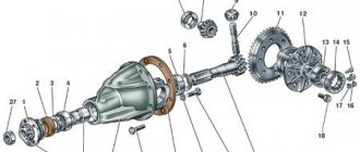
Cylinder head (cylinder head) bolt. M12×1.25:
1st step - tighten bolts 1–10 to a torque of 20 Nm; 2nd step - tighten bolts 1–10 to a torque of 70–86 Nm, and bolt 11 to a torque of 31–39 Nm. 3rd step - then turn bolts 1–10 by 90°; 4th move - and another 90°;
Camshaft bearing housing stud nut M8 18.33-22.64(1.87-2.30)
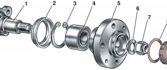
Checking and adjusting the clearance in the front wheel hub bearings of Niva Chevrolet
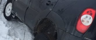
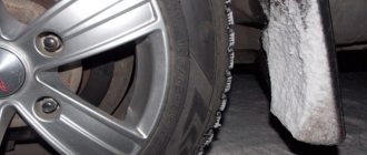
With increased clearance in the front wheel hub bearings, vibration in the steering wheel is observed in a certain speed range. At the same time, the tires wear out unevenly (in patches), and the service life of the bearings themselves sharply decreases. The complete absence of clearance, at which tight rotation of the hub is observed, also leads to a decrease in service life.
The clearance in the front wheel hub bearings should be no more than 0.15 mm.
You will need: a wrench for the wheel bolts, a 27 wrench, a hammer.
1. Place the car on supports
2. Remove the corresponding wheel.
3. Remove the decorative cap,
4. Unlock the hub nut and
6. Screw and tighten the new hub nut to a torque of 19.6 Nm (2 kgf m), while turning the hub approximately 90° in both directions 2-3 times to self-align the bearings.
It must be taken into account that if there is large play in the bearing, the bearing must be replaced. Since when the bearing is tightened with increased wear, progressive wear of the bearing will begin. And eliminating the backlash can only be a temporary measure.
7. Loosen the adjusting nut and tighten it again to a torque of 6.8 N·m (0.7 kgf·m).
8. Loosen the adjusting nut approximately 25°.
9. Lock the hub nut (by jamming the collar of the nut into two grooves on the front wheel drive outer joint housing trunnion).
10. Install the removed parts in the reverse order of removal.
The gap is most accurately determined using an indicator. If there is no indicator, swing the hanging wheel in a vertical plane. If you feel any play, the bearing clearance may need to be adjusted. To make a final check of the bearing, have an assistant press and hold the brake pedal. Rock the wheel again in a vertical plane. The disappearance of wheel play during such a check confirms the need to adjust the clearance in the bearings
When adjusting, be sure to replace the hub nuts with new ones, since after adjustment the nut may take its previous position and it will not be possible to securely lock it, since the collar in the right place will already be damaged by the previous locking. As a last resort, if possible, use a nut from another car.
Transmission
- Reversing light switch M14x1.5 28.4-45.1 (2.9-4.6)
- Bolt securing the clutch housing to the engine M12×1.25 53.9-87.2 (5.5-8.9)
- Nut securing the clutch housing to the gearbox M10×1.25 31.8-51.4 (3.25-5.25)
- Nut securing the clutch housing to the gearbox M8 15.7-25.5(1.6-2.6)
- Rod clamp cover bolt M8 15.7-25.5(1.6-2.6)
- Rear cover mounting nut M8 15.7-25.5(1.6-2.6)
- Nut of the rear end of the secondary shaft M20x1.0 66.6-82.3 (6.8-8.4)
- Intermediate shaft bearing clamping washer bolt M12×1.25 79.4-98.0 (8.1-10.0)
- Bolt securing the fork to the gearshift rod MB 11.7-18.6(1.2-1.9)
Adjusting the wheel bearing
To work, you will need an indicator and a torque wrench.
To prepare for adjusting the wheel bearing, you must perform the following operations:
The adjustment is carried out as follows:
Important: when tightening, it is necessary to rotate the hub in different directions.
You can adjust the hub play without using a torque wrench. To do this you need:
Video instructions for adjusting the wheel bearing
You can install IVECO non-adjustable bearings on Chevy Niva. To do this, you need to buy the appropriate hubs or remake the old ones. For the rework you will need a jig boring machine. In addition to boring the mounting hole, you will have to make spacer rings. Drawings of parts are provided at the link.
Attention! Rework makes sense only if you have turning skills and free access to the machine. Otherwise, it is easier and cheaper to buy ready-made hubs for non-adjustable bearings.
The design of the rear wheel mounting of the Chevrolet Niva is very different. However, they also use bearings that need periodic replacement. They are replaced either together with the axle shafts or separately. The second option is much cheaper, but requires good metalworking skills and a torch to heat the metal.
To work you will need:
Replacement of bearings is carried out as follows:
Assembly is performed in the reverse order of disassembly. The bearing does not need adjustment.
A visual process of replacing a Niva Chevrolet axle bearing
Source
Transfer case
- Nut securing the suspension bracket to the pillow axis M10×1.25 26.5-32.3 (2.7-3.3)
- Nut securing the suspension bracket to the body M8 15.0-18.6(1.53-1.90)
- Nut securing transfer case housing covers, front axle drive housing, speedometer drive housing, control lever bracket M8 14.7-24.5(1.5-2.5)
- Differential lock switch M16×1.5 28.4-45.0 (2.9-4.6) Bolt securing the forks to the gear shift rods MB 11.8-18.6 (1.2-1.9)
- Bolt securing the forks to the differential lock rod M12×1.25 11.7-18.6(1.2-1.9)
- Nut securing the propeller shaft flange to the drive shaft and to the drive shafts of the front and rear axles M16×1.5 96.0-117.6(9.8-12.0)
- Driven gear mounting bolt М10×1.25 66.6-82.3 (6.8-8.4)
- Nut for securing the rear bearing of the drive shaft and the rear bearing of the intermediate shaft M18×1.5 96.0-117.6(9.8-12.0)
Symptoms of a problem
Bearing wear manifests itself as the following symptoms:
If such manifestations occur, you need to check the condition of the wheel bearings. To do this, jack up the car and rock the wheel in different directions. Play and knocking in the bearing area indicates the need for replacement and adjustment. The malfunction may also manifest itself in the form of noise when the wheel rotates.
Separately, it is worth mentioning two problems that arise during the operation of the Chevrolet Niva:
1. The hubs get hot. It is important to understand that when braking, the kinetic energy of the car is converted into thermal energy. As a result, the brake discs and the hubs on which they are attached become very hot. Heating of the part during movement, and not during braking, indicates wear of the bearing or its incorrect adjustment.
Front suspension
- Nut of the lower bolts securing the cross member to the body side members M 12×1.25 66.6-82.3 (6.8-8.4)
- Nut of the upper bolts securing the cross member to the body side members M 12×1.25 66.6-82.3 (6.8-8.4)
- Nut of the bolt securing the rebound buffer bracket to the cross member M8 15.1-18.6 (1.53-1.90)
- Nut of the upper arm axle mounting bolt M 12×1.25 66.6-82.3 (6.8-8.4)
- Nut securing the upper end of the shock absorber M10×1.25 27.4-34.0 (2.80-3.46)
- Nut securing the lower end of the shock absorber M10×1.25 50.0-61.7 (5.1-6.3)
- Front wheel hub bearing nut M 18×1.5 cm, “Chassis”, p. 169
- Bolt securing the caliper to the steering knuckle M10×1.25 29.1-36.0 (2.97-3.67)
- Anti-roll bar mounting nut M8 15.0-18.6(1.53-1.90)
- Nut securing ball pins to steering knuckle M 14×1.5 83.3-102.9 (8.5-10.5)
- Nut for fastening the brace to the suspension cross member M 12×1.25 66.6-82.3 (6.8-8.4)
- Nut for fastening the extension to the body M 16×1.5 104.9-169.5 (10.7-17.3)
- Nut connecting the lower arm axis to the cross member M 16×1.5 114.7-185.2(11.7-18.9)
- Nut for fastening ball joints to suspension arms M8 20.60-25.75 (2.10-2.63)
- Wheel bolt nut M 12×1.25 62.4-77.1 (6.37-7.87)
- Upper suspension arm axle nut M 14×1.5 63.7-102.9 (6.5-10.5)
- Nut of bolts securing the swing arm M 12×1.25 66.6-82.3 (6.8-8.4)
How to properly tighten the hub nut on a Chevrolet Niva
With an increased clearance in the front wheel hub bearings, vibration in the steering wheel is observed in a certain speed range.
In this case, the tires wear out unevenly (in patches), and the service life of the bearings themselves sharply decreases. The complete absence of clearance, at which tight rotation of the hub is observed, also leads to a decrease in service life.
The clearance in the front wheel hub bearings should be no more than 0.15 mm.
You will need: a wrench for the wheel bolts, a 27 wrench, a hammer.
Place the car on supports
Remove the corresponding wheel.
Remove the decorative cap, loosen the hub nut and, holding the hub from turning with a suitable wrench, unscrew the nut.
Screw and tighten the new hub nut to a torque of 19.6 Nm (2 kgf m), while turning the hub approximately 90° in both directions 2-3 times to self-align the bearings
It must be taken into account that if there is large play in the bearing, the bearing must be replaced.
Since when the bearing is tightened with increased wear, progressive wear of the bearing will begin.
And eliminating the backlash can only be a temporary measure.
Loosen the adjusting nut and tighten it again to a torque of 6.8 Nm (0.7 kgf m)
Loosen the adjusting nut approximately 25°.
Lock the hub nut (by jamming the collar of the nut into two grooves on the front wheel drive outer joint housing trunnion).
Install the removed parts in the reverse order of removal.
The gap is most accurately determined using an indicator.
If there is no indicator, swing the hanging wheel in a vertical plane.
If you feel any play, the bearing clearance may need to be adjusted.
To make a final check of the bearing, have an assistant press and hold the brake pedal.
Rock the wheel again in a vertical plane.
The disappearance of wheel play during such a check confirms the need to adjust the clearance in the bearings
When adjusting, be sure to replace the hub nuts with new ones, since after adjustment the nut may take its previous position and it will not be possible to securely lock it, since the collar in the right place will already be damaged by the previous locking.
As a last resort, if possible, use a nut from another car.
After adjusting the clearance in the hub bearings, make sure that the wheel rotates easily.
Perform a final check of the correctness of the adjustment by assessing the degree of heating of the hubs after driving the car for about 1 km without using the brakes.
Source
Steering
- Steering housing mounting bolt nut M10×1.25 33.3-41.2 (3.4-4.2)
- Nut of the pendulum arm bracket mounting bolt M10×1.25 33.3-41.2 (3.4-4.2)
- Ball pin nut for steering linkages** M 14×1.5 42.1-53.0 (4.3-5.4)
- Nut securing the steering shaft bracket and ignition switch M8 15.0-18.6 (1.53-1.90)
- Steering wheel nut M 16×1.5 31.4-51.0 (3.2-5.2)
- Bipod fastening nut M20x1.5 199.9-247.0 (20.4-25.2)
- Pendulum arm axis nut M 14×1.5 63.7-102.9 (6.5-10.5)
How to change the wheel bearing on a Chevrolet Niva with your own hands?
For repairs you will need:
The replacement process is divided into five stages:
Work is carried out on a level area. The presence of an inspection hole is not necessary.
To change bearings, you must perform the following steps:
Attention! Without a puller to remove the rod pin, you can disconnect it in another way. To do this, you will have to dismantle the bipod of the steering mechanism from the steering knuckle.
Important: the clips are installed with the wide edge inward. You can make pressing easier by preheating the hub.
Detailed video about replacing wheel bearings
Replacement process and tightening torque
Required Tools
To carry out this work on replacing the cylinder head gasket of the Niva Chevrolet and tightening the cylinder head bolts, you should prepare:
- Phillips and slotted screwdriver;
- set of open-end wrenches;
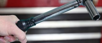
- torque wrench.
Without the last element, tightening the cylinder head pulleys will be impossible.
Step-by-step instruction
- Initially, of course, you need to dismantle the cylinder head cover itself.
- Then place a container under the bottom of the car to collect the waste refrigerant. Unscrew the drain plug and drain the antifreeze.
- Then you should disconnect the throttle cable from the receiver and assembly.
- After this, the timing pulley should be removed along with the bearing housing.
- Next, we dismantle the valve lever, and then unscrew the lever supports themselves. Also dismantle the engine fluid supply ramp to the hydraulic supports.
- Now you need to disconnect the cable harness from the TPS. In the same way, disconnect the wiring from the idle speed sensor and antifreeze.
- You need to squeeze the plastic clip and then disconnect the connector with the wires that are designed to power the injectors. Here you also need to remember to disconnect the wiring harness from the knock sensor.
- Now disconnect the high voltage cables from the spark plugs. Also disconnect the cable that powers the engine temperature control device.
- Slightly compress and disconnect the exhaust pipe from the intake manifold. Then the upper screw securing the inlet tube spacer and, slightly loosening the lower screw, the spacer should be moved to the side.
- The clamp should be loosened slightly, then the adsorber purge pipe should be disconnected from the throttle assembly.
- The clamps must be loosened and the cooling system pipes must be disconnected from the cylinder head.
- Using open-end wrenches, you now need to disconnect the fuel lines. To do this, unscrew the nuts of the fuel hoses intended for draining and supplying gasoline.
- Now use a wrench to remove the top screw that secures the rear intake tube brace. The bottom screw should also be loosened a little. After these steps, the spacer must be removed to the side.
- When all the above steps have been completed, the camshaft pulley drive chain tensioner should be removed.
- Then dismantle the brackets that secure the power steering device.
- Now you can remove the chain with the timing pulley star.
- After this, using a socket with an extension, you will need to unscrew the screws securing the cylinder head, and then dismantle it.
- The cylinder head gasket can now be removed. Mount a new component in its place, having previously lubricated its perimeter with sealed glue. Actually, at this point the work on replacing the cylinder head gasket in the Chevrolet Niva can be considered completed. All further work on assembling the power unit must be performed in the reverse order. But that is not all. To ensure a reliable fit of the cylinder head to the block itself, you need to correctly tighten the screws and maintain the tightening torque.
- The procedure itself consists of several stages. First of all, using a torque wrench and following the order indicated in the diagram, you need to tighten the screws from the first to the tenth. In this case, the tightening torque of the Niva Chevrolet cylinder head should be 20 Nm.
- Next, when all the bolts are tightened in turn, you need to tighten all the cylinder head screws again. The tightening torque should now be 69.4–85.7 Nm. The last, eleventh pulley needs to be tightened to 31.4–39.1 Nm.
- After these steps, the screws marked with numbers from one to ten need to be turned 90 degrees, and then, when they are all screwed, you should repeat the procedure and turn them again 90 degrees. At this point, the screw tightening procedure can be considered complete.
If all the steps were performed correctly, then after replacing the component you will no longer have the problem of engine fluid getting into the antifreeze and vice versa. But keep in mind: everything must be done according to the steps specified in this manual.
If, for example, you tighten the cylinder head bolts incorrectly, that is, do not tighten them or overtighten them, then this can result in more serious problems.
If the screw is not tightened, the cylinder head will not fit tightly to the block. This is fraught with engine fluid leakage. If, on the contrary, you overtighten the pulleys, this can cause cracks to form on the power unit. If microcracks appear, then you will have to either weld the cylinder head or replace it. Therefore, before you begin such repairs, think carefully - can you do everything right?
Symptoms of a problem
Bearing wear manifests itself as the following symptoms:
If such manifestations occur, you need to check the condition of the wheel bearings. To do this, jack up the car and rock the wheel in different directions. Play and knocking in the bearing area indicates the need for replacement and adjustment. The malfunction may also manifest itself in the form of noise when the wheel rotates.
1. The hubs get hot. It is important to understand that when braking, the kinetic energy of the car is converted into thermal energy. As a result, the brake discs and the hubs on which they are attached become very hot. Heating of the part during movement, and not during braking, indicates wear of the bearing or its incorrect adjustment.
The second option is typical for adjustable hubs. The adjusting nut must be tightened with a force of 2 kgf*m. If you tighten it further, the tapered bearings will be too tight.
Their rotation will be difficult. Prolonged operation of the machine in this condition leads to bearing failure and wheel jamming.
2. The adjusting nut is unscrewed while moving. Sometimes this happens literally after 20-50 kilometers. The phenomenon is observed in three cases: the master forgot to tighten the nut, there was a misalignment between the bearing races, or play appeared in the coupling of the CV joint with the hub.
If such manifestations occur, you need to check the condition of the wheel bearings. To do this, jack up the car and rock the wheel in different directions. Play and knocking in the bearing area indicates the need for replacement and adjustment. The malfunction may also manifest itself in the form of noise when the wheel rotates.
1. The hubs get hot. It is important to understand that when braking, the kinetic energy of the car is converted into thermal energy. As a result, the brake discs and the hubs on which they are attached become very hot. Heating of the part during movement, and not during braking, indicates wear of the bearing or its incorrect adjustment.
Also interesting: Niva Chevrolet front hub repair
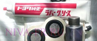
Adjustable hydraulic supports (hydraulic compensators).
REPAIR AND TECHNICAL CENTER “NIVA”
Old style hydraulic compensators.
Everyone knows what a hydraulic compensator (hereinafter referred to as hydraulic compensator) is and what function it performs. Worse than these g.k. I haven't seen anything, and their price isn't bad. The weakest point of these tensioners is that they tend to constantly unscrew (tightening torque is from 1.7 to 2.5 kg), tighten it harder, it simply will not work. Many people try to install them on various thread clamps, but I think this is not a solution. AvtoVAZ has already stopped producing cars with such cylinder head, but there are a lot of cars with cylinder head, old model, but not everyone has the opportunity to change the cylinder head to a new model. There is a good way, already tested on many cars, to avoid unscrewing the main gearbox. Everything is very simple - tighten them not by 2 kg, but by 4 kg. We did it!!!
Consequences of an unscrewed g.k.
When starting a cold internal combustion engine, a knocking sound is allowed. for 2 – 4 seconds. If the knocking continues for more than this time or appears on a hot internal combustion engine, it is advisable to contact a service station as soon as possible to eliminate the malfunction of the engine.
And now the most important thing for those who are delaying repairs. An unscrewed cylinder head first breaks the oil drop ramp, wears out the rocker and camshaft cam due to incorrect clearance adjustment and knocks out the threads in the cylinder head, which leads to the replacement of the cylinder head with a new model)))
Timing chain tensioner
Installed on Niva 21214 and 2123. After passing 1 maintenance, I recommend getting rid of this part and replacing it with Pilot 214 (mechanical tensioner). The hydraulic chain tensioner is very unreliable, especially when starting a cold internal combustion engine. The main malfunction of the chain tensioner is that the oil from the tensioner flows back into the system (the tightness of the tensioner is broken), and accordingly, the chain tension has weakened. And what we get: when starting the engine if the tensioner is faulty, the oil needs time to fill the tensioner and bring it into working condition. And then there are only two scenarios: the chain will rattle for 5 seconds and become tense, or the chain will simply fly off, which threatens a very expensive repair of the cylinder head.
New type hydraulic compensators.
I don't see any drawbacks in these hydraulic compensators. A very good option for the Niva family of cars. The only thing I had to deal with was unscrewed glasses, but the car mechanic who did not tighten them is to blame here (tightening torque up to 11 kg). When tightening glasses less than 4-5 kg, there is a possibility of them unscrewing. The consequences are the same as with the old sample
Please note that they are very loosely tightened at the factory.
Motor mechanic "RTC" NIVA"
Other site materials: Niva repair
Articles: Strengthening the front beam
Watt's parallelogram
Removing the hub
To do this, dismantle the conical bushing.
Unlocking the nuts is done by gently tapping them through a chisel.
After which, using a size 19 wrench, the rear and front clamps of the lever to the knuckle are unscrewed sequentially,
not forgetting to get rid of the locking plate.
Then, using the keys “17” and “10”, as well as a flat screwdriver, the brake circuit hoses are removed from the steering knuckle.
Also interesting: Suspension lift in the field yourself
Having placed the stop under the lever from below, use two “13” keys to unscrew the nut located on the bolt that secures the ball mount to the upper lever. Unscrew 2 more nuts in the same way. And take the knot to the side.
The lower ball joint is also dismantled.
When the part is freed from the fastenings, holding the steering knuckle with both hands together with the hub, brake disc, upper and lower ball joints, it is removed.
When separating parts, it may be necessary to clamp the steering knuckle in a vice, after which the hub is knocked out without extra effort.
Next, the bolts securing the steering knuckle to the lever are removed.
The brake disc is knocked out by screwing the nuts onto the stud, followed by concentrated blows to the resulting structure.
The result of the work at this stage: the brake system disc and hub are separated from each other.
They hook up the ring that protects against dirt, after which, using a “10” key, remove the casing that protects the steering knuckle.
Step-by-step instructions for replacing the cylinder head gasket
The design features of the Niva Chevrolet make it possible to remove the cylinder head without good access from below. However, the presence of an inspection hole or lift greatly facilitates access to some nuts and the coolant drain valve. There is no need to remove the engine, but it is advisable to clear the space under the hood of interfering hoses and wires.
For repairs you will need the following tools:
- set of keys and socket heads;
- powerful wrench, ratchets, extensions;
- hammer;
- flat screwdriver;
- head or special wrench 38 for cranking the crankshaft;
- torque wrench;
- brake pipe wrench (suitable for oil line).
Conventionally, all work on replacing the cylinder head gasket on a Niva can be divided into 2 stages: removing all attachments and all electrical sensors from the cylinder head, removing the timing mechanism and attaching the head to the cylinder block.
Procedure for removing the cylinder head of a Chevy Niva
The work algorithm is as follows:
- Drain the antifreeze from the radiator and engine block. To do this, unscrew the plug on the block with a 13 key. In this case, there is no need to drain the oil from the crankcase. Remove the terminal from the battery. We move the gearbox to neutral position.
- While the coolant is draining, we begin to disassemble the engine from the hood side. We unscrew the throttle valve, remove the throttle cable, remove the wires from the spark plugs, disconnect the electrical connectors of the injectors, TPS, IAC, oil pressure and coolant temperature sensor.
- Now you can disconnect all the cooling system hoses going to the thermostat, heater core and throttle body heating. Remove the brake booster hose from the intake manifold.
- We take the engine wiring harness and all removed hoses to the side and secure them if necessary.
- We unscrew the protective screen of the exhaust manifold, loosen the 4 nuts securing the exhaust pipe to the exhaust manifold. For the convenience of further actions, the exhaust pipe can be removed from the lower mounts and completely lowered under the car.
- On a Chevy Niva with power steering, the pump mounting bracket will interfere with us. It is not necessary to remove it completely - just unscrew the fastening bolts and carefully hang it on the wire.
- Now you can start opening the engine. Remove the valve cover. Using a special wrench, unscrew the oil line to the hydraulic compensators and chain tensioner.
- Set the piston of the first cylinder to TDC until the marks align by turning the crankshaft. Loosen the chain tensioner and unscrew the top sprocket. We immediately fix it in this position with wire to prevent the circuit from jumping and phase failure.
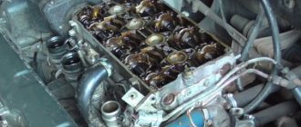
- Unscrew the 10 nuts securing the camshaft housing with bearings. You need to unscrew evenly around the entire perimeter (according to the tightening order in the instructions). Remove the assembly from the engine.
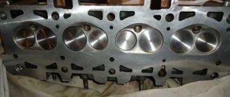
- Access to 10 cylinder head mounting bolts is now open. You need to tear them off with a wrench, starting from the middle and moving to the outer bolts. The bolts are removed from their places and checked for thread condition and possible elongation (no more than 117 mm).
- Gently tapping and prying from below with a screwdriver, pull the cylinder head out of its place. After which you can remove it from the engine along with the collectors. The mass of this unit allows you to perform the operation yourself.
After removing the old gasket, possible damage and wear of the surfaces are assessed. If no repairs are required, the valves do not have carbon deposits, and all dimensions are within tolerance, then you can immediately begin replacing the cylinder head gasket and assembling the engine.
Niva cylinder head bolts, installation
To work with bolts, a special tool is required. E16 head, which is not always included in universal tool kits, and a torque wrench. To make the process logically complete, the price list includes an E16 head (Sata or Force) and a torque wrench (JTK).
I won’t invent anything about the installation technology, just completely follow the factory manual.
- Submerge the bolts in a container of engine oil.
- Let it drain. Exposure for at least 30 minutes.
- Wrap and tighten according to the diagram.
Stage 1 – tightening with torque (12…20) N.m;
Stage 2 – tightening torque (50...70) N.m;
Stage 3 – turning the bolts by 90-110 degrees;
Stage 4 – turning the bolts 90-110 degrees.
Tightening torque of bolt 11 (at the cylinder head tail): preliminary – (14…16) N.m; final – (32…40) N.m.
VAZ 21213 | antifreeze | Niva
The cooling system is filled year-round with a mixture of water and antifreeze with an anti-corrosion additive from the vw/seat concern. This mixture prevents freezing and corrosion of the cooling system, salt deposits and, in addition, increases the boiling point of the coolant. In the circulation circuit, as a result of the expansion of the liquid when heated, increased pressure is created, which also contributes to an increase in the boiling point of the coolant. The pressure is limited by a valve located in the expansion tank cap, which opens at a pressure of 1.4 - 1.6 bar. For the engine cooling system to function flawlessly, a high boiling point of the coolant is required. If the boiling point is too low, vapor locks can form, causing poor engine cooling. Therefore, the cooling system must be filled with a mixture of water and antifreeze all year round.
It is necessary to use antifreeze g12 plus (purple color, exact designation g 012 a8f) or another con, for example, glysantin-alu-protect-premium/g30.
If the cooling system is filled with a mixture containing g12 antifreeze (red, exact designation g 012 a8d), then red g12 antifreeze or another con, for example glysantin-alu-protect/g30, can also be used to replenish the coolant level. Note: g12 purple can be mixed with g12 red.
Attention: Do not mix red g12 antifreeze and the older green g11 antifreeze, because
this can cause severe engine damage. Coolant that is brown (the result of mixing antifreeze g12 and g11) must be replaced immediately.
Note: If a liquid with an antifreeze additive of the wrong specification accidentally ends up in the cooling system, the system must be flushed. To do this, all liquid from the cooling system should be completely drained and the system filled with clean water. Leave the engine idling for two minutes. Drain the water again and blow out the system from the side of the expansion tank with compressed air to completely empty it. Close the drain plug and fill the cooling system with a mixture of water and g12-plus antifreeze.
Attention: To replenish the cooling system (also in the warm season), only use a mixture of g12-plus (purple color) with soft, clean water. The proportion of antifreeze, also in summer, should not be lower than 40%
Therefore, when replenishing the cooling system with water, you should always add antifreeze.
In our latitudes, the coolant should provide protection against freezing down to -25 °C, or even better - down to -35 °C. The proportion of antifreeze should not exceed 60% (antifreeze protection of the coolant down to -40 °C), otherwise the antifreeze protection and cooling effect of the liquid are reduced. Note: depending on the vehicle equipment, the amount of coolant added may differ slightly from the values indicated in the table
Ratio of coolant components in liters
| engine's type | Frost protection | Quantity, l | |||
| Up to -25 °C | up to -35 °C | ||||
| g12 | Water | g12 | Water | ||
| Petrol | 2,3 | 3.3 | 2,8 | 2,8 | 5,6 |
| Diesel | 2,0 | 3,0 | 2,5 | 2,5 | 5,0 |