You can wrap the car engine block head yourself. However, for this you need to know that the tightening torque of the cylinder head bolts of the VAZ 2112 16 valves and 8 valves are different. This is justified by the different design of internal combustion engines.
The user manual describes the reasons when work needs to be done.
- Oil leakage from the contact points between the block and the head. Usually expressed in the appearance of dark streaks on the walls of the block, or the formation of sweaty spots on the adjacent surface.
- The appearance of a whitish emulsion on the filler cap and dipstick. This is a sign of antifreeze leaking into the crankcase compartment. It may also be accompanied by foaming of the liquid in the expansion tank and the appearance of oily films there.
- Gasket burnout. Usually accompanied by the smell of gasoline from the cooling system or oil. While the engine is running, fuel under pressure seeps into the compartments, where it dissolves lubricant or antifreeze.
- Overhaul of the internal combustion engine, usually the cause is overheating, maintenance of the piston group or serious breakdowns.
- After dismantling the old head and installing a new one.
If there is no urgent need to climb into the engine structure, there are no lubricant leaks anywhere, there is no need to perform the procedure.
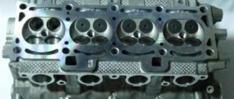
What is a cylinder head?
In order to carry out any manipulations with this unit, it is necessary to understand the purpose and operating principle of the device.
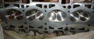
The cylinder head on the VAZ-2112 model we are considering is made of two options: cast iron, aluminum. Essentially, to put it bluntly, this is the engine cover. One of the most important components of a vehicle, which is responsible for:
- combustion of gasoline in the engine;
- removal of exhaust gases during the combustion process.
Secondary functions performed by the cylinder head:
- the functional option is carried out thanks to the work of support washers, valve bushings and other parts located in the head;
- thanks to the hole in it, the chain tensioner and the drive of the pulley distributor are installed.
The abbreviation cylinder head is used more often in the terminology of automotive components, since there is not always time to pronounce long and complex names. But it is clear that you need to know all the decryptions. Especially if it is an internal combustion engine (internal combustion engine) and cylinder head (cylinder head).
Therefore, the tension moment must always be adjusted and not carelessly, but correctly, otherwise its functionality will be impaired.
First of all, this is necessary to avoid moisture accumulation at the junction of components in the block and their connections. Thanks to this protection, condensate collects on a special plane to allow liquid to leak out of the engine.
Process Features
Each engine has its own torque, as does the pin tightening pattern. The indicator of this moment is influenced not only by the type of engine, but also by other factors that you need to know if you decide to carry out this procedure yourself.
- how well the pin holes are lubricated and the very condition of the elements;
- the quality of the bolts plays a big role - bad or old ones may not survive tightening;
- if the thread or the pin itself is deformed, it is better not to tighten it. Because after a short period of time, all elements that do not meet operating standards will fail.
The most urgent need for the tensioning procedure occurs when dismantling the cylinder head, as well as when reinstalling it.
Some car enthusiasts tighten very elongated bolts in 4 stages. In this case, at the second step the torque is 70-85 N*m, which is absolutely unacceptable when working with a Lada Priora engine with 16 valves.
The correct sequence of tightening the keys is very important. Only in this case will the head correctly perform its primary and secondary functions.
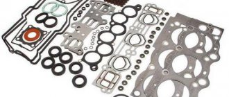
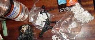
Before installation, be sure to clean all threaded bushing holes. Then all the bushings are placed in place, and a gasket is placed on top. All metal elements must be free of grease.
No sealants or other lubricating oils are used during gasket installation.
General rules for performing work
A number of general rules that must be followed when installing the block head:
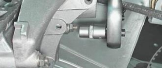
- It is important to strictly observe the tightening torque. For these purposes, a special tool is used - a torque wrench. It is not recommended to perform this operation with regular keys;
- The head bolts must be pulled smoothly, jerking is not allowed. Since the tightening force on the last approaches is significant, extending the wrench arm with a pipe can simplify the procedure and ensure smooth, uniform tightening;
- Before installing the bolts, you need to carefully inspect the condition of the threads on them. There should be no dirt or foreign particles on the coils.
- The threads of fasteners should be lubricated with engine oil before tightening. But you should not pour grease into the holes for the bolts (especially for “blind” holes), since in the future it will not allow the fasteners to be fully tightened.
Procedure for installation and dismantling
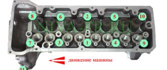
The cylinder block is the basis for mounting the head, which is held on by 10 screws. Unscrewing is carried out with a special socket wrench - “ten”.
The photo shows the correct folding order:
- Top right corner.
- Bottom right corner.
- Top left corner.
- Bottom left corner.
- Top second from left.
- Top second from the right.
- Second bottom from the right.
- Second bottom from the left.
- Top in the middle.
- Bottom in the middle.
The procedure and torque for tightening the cylinder head on a VAZ-2112 with 16 valves: tightening the cylinder head bolts
VAZ cars of the 2112 family were produced with two 16-valve valves: 21120 and 21124. The cylinder head of these engines has different intake ports. In theory, there are no other differences. And therefore, the tightening torque of the bolts on the VAZ-2112 cylinder head will be the same if we talk about any 16-valve internal combustion engine. Tightening is performed in three steps, although repair books give another option (it is for 8-valve engines).
The following video shows how the cylinder head is installed in 5 minutes:
Video
The video (Auto_Remont channel) describes in detail the process of installing and assembling the cylinder head on a VAZ 2112.
Do you have any questions? Specialists and readers of the AUTODVIG website will help you ask a question
Was this article helpful?
Thank you for your opinion!
The article was useful. Please share the information with your friends.
Yes (60.00%)
No (40.00%)
X
Please write what is wrong and leave recommendations on the article
Cancel reply
Rate this article: ( 5 votes, average: 4.60 out of 5)
Discuss the article:
Installation and dismantling procedure
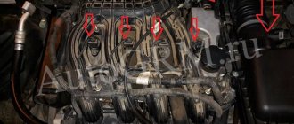
The part called the cylinder head is attached to the cylinder block with 10 screws. They are unscrewed with a 10mm socket wrench. The procedure for dismantling the cylinder head is shown in the first photo.
Reversal sequence (1-10)
The standard screw length is 9 3 mm. If the screw has been pulled out to at least 95 mm, it is replaced with a new one (AvtoVAZ requirement).
During installation, a different scheme is used (photo 2). Each screw is lubricated with machine oil, otherwise the efforts will be reduced to nothing.
The order of tightening the head is indicated in this photo
Tightening torque for cylinder head cover bolts
For VAZ-2112, the cylinder head tightening torque is standardized:
- First pass – the force is 20 N*m;
- Each screw is turned 90 degrees to the right;
- Wait 20 minutes, then turn the screws another 90 degrees.
D&V | Topic author: Roswel
Tightening torque of the cylinder head bolts on the VAZ 2108, VAZ 2109, VAZ 21099 engine Part Thread Tightening torque, N m (kgf m) Engine Cylinder head bolts M12x1, 25 1st step: 20.0 (2.0) 2 1st step: 71, 0–87, 0 (7, 1–8, 7) 3rd step: tighten by 90° 4th step: tighten again by 90° Nut of the stud securing the intake pipe and exhaust manifold M8 21, 0–26, 0 (2, 1–2, 6) Nut securing the tension roller M10x1, 25 34, 0–42, 0 (3, 4–4, 2) Nut of the stud securing the camshaft bearing housing M8 18, 7–23 , 0 (1, 87–2, 30) Bolt for fastening the camshaft pulley M10 68, 0–85, 0 (6, 8–8, 5) Bolt for fastening the housing of auxiliary units M6 6, 8–8, 4 (0, 68 –0, 84) Nuts of studs securing the outlet pipe of the cooling jacket M8 16, 0–23, 0 (1, 6–2, 3) Bolt securing the main bearing caps M10x1, 25 69, 0–84, 0 (6, 9–8 , 4) Oil sump mounting bolt M6 5, 0–8, 0 (0, 5–0, Connecting rod cover bolt nuts M9x1, 0 44, 0–54, 0 (4, 4–5, 4) Flywheel mounting bolt M10x1, 25 62, 0–87, 0 (6, 2–8, 9) Coolant pump mounting bolt М6 78, 0–80, 0 (0, 78–0, 80) Crankshaft pulley mounting bolt М12х1, 25 99, 0 –110, 0 (9, 90–11, 0) Bolt for fastening the supply pipe of the coolant pump M6 4, 1–5, 1 (0, 41–0, 51) Nut for fastening the exhaust pipe of the muffler M8x1, 25 21, 0–26 , 0 (2, 1–2, 6) Nut securing the flange of the additional muffler M8x1, 25 16, 0–23, 0 (1, 6–2, 3) Nut securing the front engine mount bolt M10 42, 0–51, 0 ( 4, 2–5, 1) Nut of the bolt securing the left engine mount M10 42, 0–51, 0 (4, 2–5, 1) Nut of the bolt securing the left suspension bracket to the engine M10 32, 0–51, 0 (3, 2–5, 1) Nut of the bolt securing the rear suspension of the engine M10 28, 0–34, 0 (2, 8–3, 4) Nut of the bolt securing the rear suspension bracket to the engine M12 62, 0–98, 0 (6, 2– 9, Bolt for fastening the oil receiver to the main bearing cover M6 8, 0–10, 0 (0, 8–1, 0) Bolt for fastening the oil receiver to the pump M6 7, 0–8, 0 (0, 7–0, Bolt for fastening the oil pump М6 8.5–10.0 (0.85–1.0) Oil pump housing mounting bolt М6 7.2–9.2 (0.72–0.92) Oil pump pressure reducing valve plug М16х1.5 46.0 –73, 0 (4, 6–7, 3) Oil filter fitting М20х1, 5 38, 0–87, 0 (3, 8–8, 7) Oil pressure warning lamp sensor М14х1, 5 24, 0–27, 0 (2, 4–2, 7) Carburetor mounting nuts M8 13, 0–16, 0 (1, 3–1, 6) Cylinder head cover mounting nut M6 2, 0–4, 7 (0, 2–0, 47) Clutch Nut securing the clutch housing to the engine block M12x1, 25 55, 0–88, 0 (5, 5–8, Bolt securing the clutch housing to the engine block M12x1, 25 55, 0–88, 0 (5, 5–8 , Bolt for fastening the flange of the guide sleeve of the clutch release bearing M6 5.0–6.5 (0.5–0.65) Bolt for fastening the clutch housing to the flywheel M8 19.0–31.0 (1.9–3.1) Nut securing the clutch housing to the gearbox M8 16, 0–26, 0 (1, 6–2, 6) Bolt securing the bottom cover to the clutch housing M6 4, 9–7, 8 (0, 49–0, 78) Gearbox Taper screw for fastening the drive rod joint M8 16, 6–20, 0 (1, 66–2, 0) Bolt for fastening the gear selection mechanism M6 5, 1–8, 2 (0, 51–0, 82) Bolt for fastening the shift lever housing gears M8 16, 0–26, 0 (1, 6–2, 6) Nut securing the drive rod clamp M8 16, 0–26, 0 (1, 6–2, 6) Nut of the rear end of the primary and secondary shafts M20x1, 5 123, 0–149, 0 (12, 3–14, 9) Reversing light switch M14x1, 5 29, 0–45, 0 (2, 9–4, 5) Bolt securing the forks to the rod M6 12, 0– 19, 0 (1, 2–1, 9) Bolt for fastening the clamp cover M8 16, 0–26, 0 (1, 6–2, 6) Bolt for fastening the differential driven gear M10x1, 25 65, 0–83, 0 (6 , 5–8, 3) Nut fastening the speedometer drive housing M6 4, 5–7, 2 (0, 45–0, 72) Nut fastening the gear selector lever axis M8 16, 0–26, 0 (1, 6–2, 6) Nut securing the rear cover to the gearbox housing M8 16, 0–26, 0 (1, 6–2, 6) Reverse fork lock plug M16x1, 5 28, 0–45, 0 (2, 8–4, 5) Conical screw for fastening the gear selector rod lever M8 28, 0–35, 0 (2, 8–3, 5) Bolt for fastening the clutch housing and gearbox M8 16, 0–26, 0 (1, 6–2, 6) Filler and drain plugs M22x1.5 29.0–46.0 (2.9–4.6) Front suspension Nut securing the upper support of the telescopic strut to the body M8 20.0–24.0 (2.0–2.4 ) Nut securing the ball pin to the lever M12x1, 25 80, 0–96, 0 (8, 0–9, 6) Nut of the eccentric bolt securing the telescopic strut to the steering knuckle M12x1, 25 79, 0–96, 0 (7, 9– 9, 6) Bolt for fastening the telescopic strut to the steering knuckle М12х1, 25 79, 0–96, 0 (7, 9–9, 6) Bolt and nut for fastening the suspension arm to the body М12х1, 25 79, 0–96, 0 (7 . 4, 3–5, 3) Nut securing the stabilizer bar to the body M8 13, 0–16, 0 (1, 3–1, 6) Bolt securing the extension bracket to the body M10x1, 25 43, 0–53, 0 (4, 3–5, 3) Nut securing the telescopic strut rod to the upper support M14x1, 5 67, 0–82, 0 (6, 7–8, 2) Bolt securing the ball joint to the steering knuckle M10x1, 25 50, 0–63, 0 (5, 0–6, 3) Front wheel hub fastening nut М20х1, 5 225, 0–250, 0 (22, 5–25, 0) Wheel fastening bolt М12х1, 25 65, 0–95, 0 (6, 5 –9, 5) Rear suspension Nut for lower shock absorber mounting M12x1, 25 68, 0–84, 0 (6, 8–8, 4) Nut for mounting rear suspension arm M12x1, 25 68, 0–84, 0 (6, 8– 8, 4) Nut for fastening the suspension arm brackets М10х1, 25 28, 0–34, 0 (2, 8–3, 4) Nut for the upper fastening of the shock absorber М10х1, 25 51, 0–63, 0 (5, 1–6, 3 ) Nut of rear wheel hub bearings М20х1, 5 190, 0–225, 0 (19, 0–22, 5) Brakes Bolt securing the brake cylinder to the caliper М12х1, 25 117, 0–150, 0 (11, 7–15, 0 ) Bolt for fastening the guide pin to the cylinder M8 31, 0–38, 0 (3, 1–3, Bolt for fastening the brake caliper to the steering knuckle M10x1, 25 29, 0–36, 0 (2, 9–3, 6) Fastening bolt rear brake shield to beam M10x1, 25 35, 0–43, 0 (3, 5–4, 3) Nut securing the vacuum booster bracket to the bracket booster M8 10, 0–16, 0 (1, 0–1, 6) Nut mounting the main cylinder to the vacuum booster M10 27, 0–32, 0 (2, 7–3, 2) Nut securing the vacuum booster to the bracket booster M10 27, 0–32, 0 (2, 7–3, 2) Brake connection fittings pipelines M10 15, 0–18, 0 (1, 5–1, Tip of the flexible hose of the front brake M10x1, 25 30, 0–33, 0 (3, 0–3, 3) Steering Mounting nut for the steering gear housing M8 15, 0–19, 0 (1, 5–1, 9) Nut for fastening the steering shaft bracket M8 15, 0–19, 0 (1, 5–1, 9) Bolt for fastening the steering shaft bracket M6 Screw in until the head comes off Fastening bolt steering shaft to gear M8 23, 0–27, 0 (2, 3–2, 7) Steering wheel mounting nut M16x1, 5 32, 0–51, 0 (3, 2–5, 1) Steering rod locknut M18x1, 5 123, 0–150, 0 (12, 3–15, 0) Nut for fastening the ball stud M12x1, 25 28, 0–33, 0 (2, 8–3, 3) Bolt for fastening the steering rod to the rack M10x1, 0 70, 0–86, 0 (7, 0–8, 6) Steering gear bearing nut М38х1, 5 46, 0–55, 0 (4, 6–5, 5) Electrical equipment Spark plug М14х1, 25 31, 0– 39, 0 (3, 1–3, 9) Nut of the generator mounting bolt M12x1, 25 59, 0–73, 0 (5, 9–7, 3)
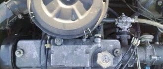
Cylinder head cover and tightening order of its bolts
The metal cover installed on the cylinder head must not allow air to pass through. At points of contact with other parts, tightness must also be maintained. Therefore, sealant is applied to the edge of the lid. An example is shown in the photo.
Cylinder head cover before installation
Here you need to use materials: Loctite-574, ANACROL, etc. The screws on the cover are tightened with an “8” key.
Recommended screw tightening torque
The recommended screw tightening torque is only 3-4 N*m. Don't be surprised: the sealant will do its job. You just need to let it dry after putting the cover in place.
You can unscrew the screws in any order. Their number is 15 or 14. When installing, it is better to follow the sequence shown below.
The order of tightening the cap is marked with numbers and arrows
There is usually no need to replace the screws - the load is too small. We wish you success.
Important points
A special torque wrench is used for tightening - no other provides uniformity and the required force.
They pull the bolts slowly and as smoothly as possible. To make the work take less effort, it is recommended to use a long lever with the wrench, for example, a piece of steel pipe.
The bolts themselves must be inspected - it is important that they have good threads. They must also be cleaned of dirt. Before tightening, they must be wiped with engine oil, but the latter cannot be poured into the holes. The problem is that, like any liquid, lubricant does not compress, which means it will prevent the screws from being tightened to the correct torque.
The order and tightening torque of the cylinder head bolts on a VAZ 2112 car
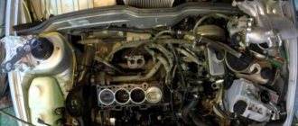
When repairing or servicing an engine, it is often necessary to remove the engine head. When reinstalling it, it is necessary to follow a certain sequence of installing the bolts and observe the correct tightening torque of the VAZ 2112 cylinder head.
When is it necessary to puff?
How to tighten the cylinder head correctly?