Gasoline engine on the "eight"
The appearance of the VAZ 21083 gasoline engine is directly related to the low quality of domestic rubber products. The fact is that at the very beginning of production, the Lada Samara family of cars was equipped with a VAZ 2108 engine, the first domestic power unit designed specifically for transverse placement under the hood of a front-wheel drive car.
However, the VAZ 2108 engine had an unpleasant feature, also characteristic of foreign engines with a timing belt drive. When the timing belt breaks, the engine pistons meet the cylinder head valves, and the latter inevitably bend, which leads to expensive repairs of the VAZ 2108 engine. On foreign cars, such a breakdown occurred extremely rarely due to the high reliability of timing belts. However, in the first Samaras, the breakage of a low-quality belt was such a frequent occurrence that it was necessary to urgently modify the engine with the help of specialists from German automakers. As a result, a new engine appeared, which became the progenitor of a whole family of power units. Assembling a VAZ 21083 engine is not a difficult task; it can be completed without the help of specialists.
Installing a crankshaft on a VAZ
Overhaul of a VAZ 21083 engine usually consists of disassembling the unit, troubleshooting parts, boring the crankshaft and cylinders, and assembling the engine. Disassembling the engine is a simple matter, troubleshooting and boring are also simple procedures. But you need to assemble the motor extremely carefully, carefully following the instructions.
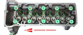
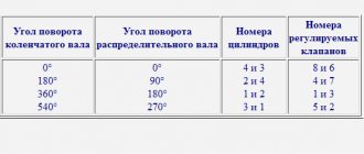
Let's start by installing the crankshaft into the cylinder block. Remember: cylinder and main bearing numbers are counted from right to left as the vehicle moves. That is, 1 cylinder is located near the pump and timing drive, and 4 is located near the clutch and gearbox.
- Turn the block upside down.
- We place the main bearing shells with the locking protrusions into the grooves of the beds. In the 3rd bed (middle) we put the liner without a groove, and in the remaining 4 - with grooves.
- Lubricate the liners with engine oil.
- Lubricate the crankshaft journals with oil and place it in bed, with the flywheel flange facing the 4th cylinder.
- We insert thrust half rings into the grooves of the middle main bearing. Each half-ring has 2 notches on one side. Using these sides we install the half rings to the crankshaft cheeks. We place the white half-ring in front (on the pulley side), and the yellow half-ring in the back (on the flywheel side).
- We rotate the half rings so that their tips are flush with the ends of the bed.
- We place liners without grooves in the main bearing caps, with locking protrusions in the grooves, and lubricate them.
- We place the main bearing caps on their corresponding beds with notches in the direction of mounting the generator. 1 cover is marked with one notch, 2 - two notches and 2 holes, 3 - three, 4 - four, 5 - two.
- We secure the covers with bolts.
- Tighten the cover bolts in the following sequence - first cover bolts 3, then 2 and 4, and finally cover bolts 1 and 5.
- After this, we rotate the shaft; if it jams, we look for the cause and eliminate it. If it doesn’t jam, check the axial clearance of the crankshaft; if it is more than 0.26 mm, replace the half rings with thicker ones. If the gap is normal, we proceed to install the oil seals and oil pump.
Installation of oil seals and oil pump
The 21083 engine lubrication system consists of an oil pump, oil receiver, filter and channels. After disassembling the engine, all channels must be washed with solvent and blown with compressed air. The oil pump should be installed together with the crankshaft seals, and the oil receiver should be installed after installing the ShPG and flywheel.
Installation procedure for seals and pump.
- Using a thick copper or brass spacer and a hammer, drive the rear oil seal into the holder all the way.
- Using lithol or other grease, glue the gasket to the other side of the holder.
- Lubricate the inner edge of the rear oil seal and the crankshaft flange with engine oil.
- We put the oil seal assembly with the holder on the flange; to do this, carefully tuck the inner edge of the oil seal onto the flange using a sharp and soft wooden stick.
Replacing the oil pump seal
- After this, we slowly move the holder along the flange all the way to the cylinder block, secure it with bolts and align it so that its edge completely coincides with the edge of the block. Only after this do we tighten all the bolts completely.
- Just like the rear one, we hammer the front crankshaft oil seal into the oil pump hole.
- Lubricate the inner edge of the oil seal and pump gears with oil. To ensure uniform lubrication, turn the gears with your finger.
- Use lithol or any other consistency to glue the gasket to the oil pump.
- We rotate the drive gear so that the protrusions on it coincide with the cuts on the front of the crankshaft.
- We put the oil pump on the shaft, use a sharp soft wooden stick to tuck the lip of the oil seal onto the crankshaft journal.
- Just like the holder, we move the oil pump all the way to the block, secure it with bolts, align the edges and tighten the bolts completely.
Replacement procedure
To replace the gasket, it is necessary, first of all, to completely dismantle the entire assembly, remove the seal that has become unusable and reassemble everything in the reverse order. At the final stage, it will be extremely important to tighten the bolts correctly.
The procedure is carried out in the same order for engines with both 16 and 8 valves. First of all, it will be necessary to disable the sensors that control the coolant temperature and oil pressure.
- before dismantling the thermostat, drain all the coolant;
- unscrew the housing protecting the air filter;
- the carburetor is left in place;
- disconnect the exhaust pipe at the muffler, on the side of the exhaust manifold.
After all this, you will need to remove the drive gear from the camshaft. Before this, the piston located in the first cylinder must be moved to top dead center (TDC).
Only after this is it possible to remove the casing and the drive belt itself, loosen the bolts securing the gear and remove it completely.
Now comes the turn of the electrical cables. In order to remove the block with the ignition wires, you will need to press the latch. The central high-voltage loop is switched off in the same way.
Next, you need to remove the fuel hose coming out of the pump - here you will need to disassemble the clamps holding it. Then the traction of both the air and throttle valve drives from the carburetor is disconnected.
You should also de-energize the solenoid valve - to do this, just disconnect all the wires leading to it. After this, remove the hose from the vacuum booster. The sleeves that supply heat to the interior are completely removed.
Only after all of the above can you remove the cylinder head. As a rule, to remove it completely, you will need to not only unscrew all the bolts, but also pull the entire assembly towards you several times.
After removing the gasket that has become unusable, it is necessary to clean all parts adjacent to it from fragments of rubber and other dirt. After this, everything needs to be wiped dry with a clean rag.
Before reassembling, you need to make sure that the bolts holding the cylinder head in place are the correct length. The thing is that they stretch out over time. The standard value is 13.55 centimeters. If they do not meet the requirements, they must be changed.
Installing the connecting rod and piston group
The connecting rod and piston group (CPG) must be installed as an assembly. It is not recommended to press the piston pin into the connecting rod head without special tools. This procedure is best left to professionals.
To install the ShPG, you need a steel mandrel in the shape of a ring. The height of the ring is 2-3 cm, the diameter of the hole is slightly larger than the diameter of the cylinder. The pistons must be mounted in such a way that the arrow on their bottom (the part adjacent to the valves) is turned towards the oil pump. The number of the connecting rod and piston must correspond to the number of the cylinder. Before installation, you need to separate the locks of the oil scraper and compression rings at an angle of 120 degrees.
- Turn the block over.
- We wipe the cylinder walls and crankpins with a dry cloth.
- Thoroughly lubricate the cylinder walls, the side surfaces of the pistons and the inside of the mandrel with oil.
- We place the mandrel on the cylinder and insert the piston and connecting rod assembly through it. We push the piston into the cylinder using a round wooden stick (hammer handle).
- Place the liner in the connecting rod cover and lubricate it with oil.
- We lay the block on its side and install the connecting rod cap so that the cylinder number on it and on the connecting rod are on the same side. We secure the cover with nuts.
- In the same way we mount the remaining pistons and connecting rods. After this, turn the cylinder block upside down and tighten all 8 nuts securing the connecting rod caps.
If you don't have a mandrel, you can cut it yourself from a piece of thick-walled steel pipe.
Assembling the flywheel, oil receiver and pump
It is important to install the flywheel so that the notch on it is located against the connecting rod cap 4, and the ring gear is adjacent to the clutch.
- Apply a thin layer of auto sealant to the bolts securing the crankshaft.
- We put the flywheel and its washer on the shaft and tighten the bolts securing it until it stops.
That's it, the flywheel is installed. We mount the oil receiver and engine crankcase.
- We change the seal ring of the oil receiver.
- Lubricate the new ring with oil.
- We put the oil receiver in its proper place and screw it to the oil pump.
- We fasten the part with 2 bolts to the second main bearing.
- Tighten the bolts.
- We cut off the excess parts of the oil seal holder and oil pump gaskets.
- Apply consistency to the lower edges of the block and glue the crankcase gasket.
- Carefully put the crankcase in place so as not to move the gasket.
- We secure the crankcase with bolts around the perimeter.
- We tighten all the bolts one by one.
Now you can rest, since the assembly is almost complete. And after the break, you need to return the pump to its place.
- We place the gasket on the pump and lubricate it with lithol or other grease.
- We install the pump with the markings facing up and screw the part to the block with 2 bolts.
That's all, the cylinder block is assembled. After this, you need to install the head, clutch, pulleys, timing covers, generator and other attachments on it.
Above are videos about dismantling and assembling the engine, which should be studied before carrying out work.
Engine repair is considered the most difficult thing in a car, because no other part contains such a huge number of interconnected elements. On the one hand, this is very convenient, because if one of them breaks down, there is no need to change the entire assembly; it is enough to simply replace the failed part; on the other hand, the more component elements, the more complex the device and the more difficult it is for those who I'm not very experienced in car repairs. However, with a strong desire, anything is possible, especially if your zeal is supported by theoretical knowledge, for example, in determining the tightening torque of the main and connecting rod bearings. If for now this phrase is a set of incomprehensible words for you, be sure to read this article before getting into the engine.
When is it necessary to remove the cylinder head?
On cars that came off the assembly line of the Volzhsky Automobile Plant, regardless of how many valves the power unit has and which drive (rear or front) is used, tightening is carried out after disassembling the cylinder block. As noted above, usually dismantling the head is needed to replace the gasket, the service life of which is 60,000 or a maximum of 80,000 kilometers. The deterioration of the sealing element seriously affects the operation of the engine, and therefore it is better not to use the machine until it is repaired.
Often the gasket wears out between the communications through which lubricant and coolant circulate. As a result, mixing of such different compositions occurs and their mutual contamination. As a result, both of them noticeably lose their operational suitability. The following symptoms are typical for this failure:
- the oil becomes thinner (sometimes the level drops or rises);
- Antifreeze takes on a brownish tint.
Repair in this situation is urgently needed.
Another problem often encountered on 8-valve VAZ-2108 is a leak in the area between the coolant supply system and the combustion chamber. This happens in the following cases:
- insufficient tightening torque;
- uneven tightening of bolts;
- factory defective gasket.
Regardless of the reason, air is directed into the cooling circuit, which leads to heating of the antifreeze. An obvious sign of trouble is strong bubbling of the fluid in the distribution tank.
It is extremely rare to see damage to the gasket in the area between the cylinders. If this happens, then compression decreases, which leads to unstable engine operation.
Often such problems arise a short time after replacing the cylinder head gasket. In this case, car owners spend a lot of effort trying to find the cause, and cannot even think that the named sealing element or incorrectly tightened head bolts are to blame. Therefore, knowledgeable craftsmen recommend first checking whether the joint between the cylinder head and the block is airtight. If characteristic streaks appear on the motor housing in the area of the head, then there is no point in looking further.
Sliding bearings, their types and role in the operation of internal combustion engines.
Main and connecting rod bearings are two types of plain bearings. They are produced using the same technology and differ from each other only in the inner diameter (for connecting rod liners this diameter is smaller).
The main task of the liners is to convert translational movements (up and down) into rotational ones and ensure uninterrupted operation of the crankshaft so that it does not wear out prematurely. It is for these purposes that the liners are installed under a strictly defined gap, in which a strictly specified oil pressure is maintained.
If this gap increases, the engine oil pressure in it becomes less, which means that the journals of the gas distribution mechanism, crankshaft, and other important components wear out much faster. Needless to say, too much pressure (reduced clearance) also does not bring anything positive, since it creates additional obstacles in the operation of the crankshaft; it may begin to jam. That is why it is so important to control this gap, which is impossible without using a torque wrench in repair work, knowledge of the necessary parameters that are prescribed by the manufacturer in the technical literature on engine repair, as well as observing the tightening torque of the main and connecting rod bearings. By the way, the tightening force (torque) of the connecting rod and main bearing cap bolts is different.
In what cases is tightening needed?
Most domestic drivers do not understand for what purpose this procedure needs to be performed, what order must be followed and what the tightening torque should be. However, every driver should know that incorrect actions during this process can damage the cylinder block. Accordingly, this procedure should be treated with all care and responsibility.
Just a few years ago, vehicle manufacturers were required to tighten the cylinder head bolts during the first maintenance of the vehicle. But now this need has disappeared and now it falls entirely on the shoulders of the drivers. If you are the owner of a VAZ 2108, then this procedure should be carried out from time to time. In what cases is it needed:
- If an oil stain appears in the place where the cylinder head connects to the block itself. This indicates a leakage of consumable fluid, which can be a consequence of both wear of the gasket itself and loosening of the pins.
- If you have done engine repairs. Sometimes even qualified specialists can make such mistakes. Therefore, the owner of a VAZ 2108 may find this information useful.
- For verification purposes. Experienced car enthusiasts recommend tightening the bolts at least every 2 thousand kilometers. In practice, there are cases when during the operation of the VAZ 2108 the pins loosen on their own.
Thus, if you notice a leak of engine fluid in the place where the head connects to the cylinder block, first of all you need to check the tightening torque of the pins.
Video.
In previous articles I explained how you can remove the engine from a VAZ 2109 without removing the gearbox and disassemble it yourself at home. Now I will explain how to assemble it.
The engine was disassembled for repair, the reason for the repair was that the VAZ 21083 engine was burning oil. After disassembly, it turned out that the oil consumption was due to the high wear of the piston group; the block was bored to accommodate the pistons of the first repair, 82.4. The crankshaft turned out to be completely new; it was not ground; only the bearings were replaced with new ones. I also lapped the valve and replaced the valve seals; the head grinding is described in the article Grinding in the head valves of a VAZ-2108 up to 15
Engine assembly
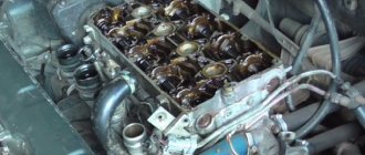
The engine begins to be assembled by installing the main bearings and crankshaft. Nowadays you can come across liners in different configurations, in the photo the liners are not very well equipped as there are no holes on the liner for the central crankshaft journal, and since this journal does not have a through hole, the lower liner will be starved of oil and this leads to faster wear of the crankshaft journal . So don’t be lazy and drill a couple of holes as shown in the photo below.
Photo. Correct installation of liners in the VAZ 21083 engine block.
Before installing the liners in the bed, carefully wipe the bed with a rag so that nothing gets under the liner; debris under the liner can lead to pinching of the crankshaft and poor heat transfer of the liner to the engine block. Install the half rings immediately as shown in the figure, lubricate the inserts with oil, and also lubricate the half rings inside with oil, then they will not fall out of their places.
Photo. The arrow shows the thrust half-rings of the VAZ 21083 engine
After installing the crankshaft into the block, be sure to check the longitudinal movement of the crankshaft, this can be done with a screwdriver as shown in the photo below, insert it from different sides, if there is movement of the crankshaft, then repair half rings are needed. Here you can already select one repair and the other standard, or lightly grind the half ring on a stone or sandpaper spread on a flat surface. Try to ensure that there is no longitudinal movement of the crankshaft; if there is longitudinal movement, the half rings may fall out during engine operation.
Photo. Checking the longitudinal movement of the crankshaft.
Now you need to put the crankshaft cushions in their places, each cushion must return to its place, you cannot install a cushion from another engine as it will be slightly different in the gap and can either clamp or give way. The photo below shows how to install the pillow correctly, note that the lock of the liner is placed next to the lock of another liner, the photo shows the installation of the third pillow with drilled holes. It doesn’t matter whether the holes are beautifully drilled or not, what is important is that oil will flow through them to the crankshaft journal.
Photo. Correct installation of the crankshaft cushion.
Immediately place all the cushions on the crankshaft but do not tighten, tighten the bolts. Now start tightening one cushion at a time, I always start with the third one, tighten it until the crankshaft is tight, turn it with a wrench as shown in the photo below. And so after each tightened pillow, try to rotate the crankshaft. You need to tighten the pillows well, but do not overdo it, as you can break the bolts. You can read more about the crankshaft in the article Repair of the crankshaft (crankshaft).
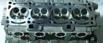
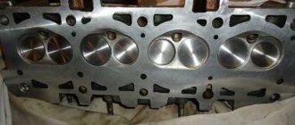
Part Features
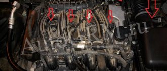
The cylinder head is a structurally quite complex part. It is a massive plate in which there are channels for the circulation of fluids of the lubrication and cooling system, and technological holes - spark plugs, for injectors (in diesel engines), mounting holes.
Also on top of the cylinder head there is a so-called “bed” of the camshaft - a seat for its installation.
Despite its massiveness, the block head is a fragile part due to the voids inside, so excessive tightening force often leads to cracks in the walls and bridges.
For the manufacture of cylinder head, two types of metals are used - aluminum (the most common) and cast iron.
To secure the latter, steel bolts or studs with nuts are used. For example, the head of the UAZ 31519 block is secured with studs.
The difference in the materials used to make the head and its fasteners has one negative factor - different thermal expansion of the components when heated, especially for aluminum cylinder heads.
Uneven tightening of fasteners (nuts, studs, etc.) during thermal expansion leads to the appearance of excessive stress in the metal structure, resulting in warping of the head.
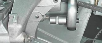
Installation of VAZ 21083 engine
Photo. Box boot VAZ 21083
You can immediately lubricate the release bearing with oil, preferably transmission oil or mixed with lithol; it can be pressed with a syringe through the slot shown in the photo below.
Photo. Release bearing of VAZ 21083 engine.
We install the engine as we removed it through the bottom without the head; this can be easily done at home with two people. To do this, pass a belt or rope under the engine, place a thick rag on the front of the car and using a pipe or crowbar you can effortlessly pull the engine onto the box, as shown in the photo below. Bolt the box, lift the engine, screw on the mount, the engine is installed, all that remains is to install the head.
Photo. Installing the VAZ 21083 engine through the bottom.