01/26/2022 10,540 VAZ 2108
Author: Ivan Baranov
In order for a car to always work correctly, all its components must function properly. This is especially true for the power unit. If you want to know how the VAZ 2108 cylinder head bolts are tightened, why is this necessary and what is needed for this? Our resource will help you understand these issues.
[Hide]
Tightening torques
| Detail | Thread | Tightening torque, N m (kgf m) |
| Engine | ||
| Cylinder head bolts | M12x1.25 | 1st move: 20.0 (2.0) 2nd move: 71.0–87.0 (7.1–8.7) 3rd move: tighten by 90° 4th move: tighten again at 90° |
| Nut of the stud securing the intake pipe and exhaust manifold | M8 | 21,0–26,0 (2,1–2,6) |
| Tension roller nut | M10x1.25 | 34,0–42,0 (3,4–4,2) |
| Camshaft bearing housing stud nut | M8 | 18,7–23,0 (1,87–2,30) |
| Camshaft pulley bolt | M10 | 68,0–85,0 (6,8–8,5) |
| Accessory housing mounting bolt | M6 | 6,8–8,4 (0,68–0,84) |
| Nuts of the studs securing the outlet pipe of the cooling jacket | M8 | 16,0–23,0 (1,6–2,3) |
| Main bearing cap bolt | M10x1.25 | 69,0–84,0 (6,9–8,4) |
| Oil sump bolt | M6 | 5,0–8,0 (0,5–0,8) |
| Connecting rod cap bolt nuts | M9x1.0 | 44,0–54,0 (4,4–5,4) |
| Flywheel bolt | M10x1.25 | 62,0–87,0 (6,2–8,9) |
| Coolant pump mounting bolt | M6 | 78,0–80,0 (0,78–0,80) |
| Crankshaft pulley bolt | M12x1.25 | 99,0–110,0 (9,90–11,0) |
| Coolant pump inlet pipe mounting bolt | M6 | 4,1–5,1 (0,41–0,51) |
| Muffler exhaust pipe fastening nut | M8x1.25 | 21,0–26,0 (2,1–2,6) |
| Nut securing the flange of the additional muffler | M8x1.25 | 16,0–23,0 (1,6–2,3) |
| Front engine mount bolt nut | M10 | 42,0–51,0 (4,2–5,1) |
| Left engine mount bolt nut | M10 | 42,0–51,0 (4,2–5,1) |
| Nut of the bolt securing the left suspension bracket to the engine | M10 | 32,0–51,0 (3,2–5,1) |
| Rear engine mount bolt nut | M10 | 28,0–34,0 (2,8–3,4) |
| Nut of the bolt securing the rear suspension bracket to the engine | M12 | 62,0–98,0 (6,2–9,8) |
| Bolt securing the oil receiver to the main bearing cover | M6 | 8,0–10,0 (0,8–1,0) |
| Bolt securing the oil receiver to the pump | M6 | 7,0–8,0 (0,7–0,8) |
| Oil pump mounting bolt | M6 | 8,5–10,0 (0,85–1,0) |
| Oil pump housing bolt | M6 | 7,2–9,2 (0,72–0,92) |
| Oil pump pressure reducing valve plug | M16x1.5 | 46,0–73,0 (4,6–7,3) |
| Oil filter fitting | M20x1.5 | 38,0–87,0 (3,8–8,7) |
| Oil pressure warning light sensor | M14x1.5 | 24,0–27,0 (2,4–2,7) |
| Carburetor mounting nuts | M8 | 13,0–16,0 (1,3–1,6) |
| Cylinder head cover nut | M6 | 2,0–4,7 (0,2–0,47) |
| Clutch | ||
| Nut securing the clutch housing to the engine block | M12x1.25 | 55,0–88,0 (5,5–8,8) |
| Bolt securing the clutch housing to the engine block | M12x1.25 | 55,0–88,0 (5,5–8,8) |
| Clutch release bearing guide flange bolt | M6 | 5,0–6,5 (0,5–0,65) |
| Bolt securing clutch housing to flywheel | M8 | 19,0–31,0 (1,9–3,1) |
| Nut securing the clutch housing to the gearbox | M8 | 16,0–26,0 (1,6–2,6) |
| Bolt securing the bottom cover to the clutch housing | M6 | 4,9–7,8 (0,49–0,78) |
| Transmission | ||
| Taper screw for fastening the drive rod joint | M8 | 16,6–20,0 (1,66–2,0) |
| Gear selector mounting bolt | M6 | 5,1–8,2 (0,51–0,82) |
| Shift Lever Housing Bolt | M8 | 16,0–26,0 (1,6–2,6) |
| Nut securing the drive rod clamp | M8 | 16,0–26,0 (1,6–2,6) |
| Nut of the rear end of the primary and secondary shafts | M20x1.5 | 123,0–149,0 (12,3–14,9) |
| Reversing light switch | M14x1.5 | 29,0–45,0 (2,9–4,5) |
| Bolt securing the forks to the rod | M6 | 12,0–19,0 (1,2–1,9) |
| Fastener cover bolt | M8 | 16,0–26,0 (1,6–2,6) |
| Differential driven gear bolt | M10x1.25 | 65,0–83,0 (6,5–8,3) |
| Speedometer drive housing fastening nut | M6 | 4,5–7,2 (0,45–0,72) |
| Gear selector shaft nut | M8 | 16,0–26,0 (1,6–2,6) |
| Nut securing the rear cover to the gearbox housing | M8 | 16,0–26,0 (1,6–2,6) |
| Reverse fork lock plug | M16x1.5 | 28,0–45,0 (2,8–4,5) |
| Tapered screw for securing the gear selector lever | M8 | 28,0–35,0 (2,8–3,5) |
| Clutch housing and gearbox mounting bolt | M8 | 16,0–26,0 (1,6–2,6) |
| Filler and drain plugs | M22x1.5 | 29,0–46,0 (2,9–4,6) |
| Front suspension | ||
| Nut securing the upper support of the telescopic strut to the body | M8 | 20,0–24,0 (2,0–2,4) |
| Nut securing the ball pin to the lever | M12x1.25 | 80,0–96,0 (8,0–9,6) |
| Nut of the eccentric bolt securing the telescopic strut to the steering knuckle | M12x1.25 | 79,0–96,0 (7,9–9,6) |
| Bolt securing the telescopic strut to the steering knuckle | M12x1.25 | 79,0–96,0 (7,9–9,6) |
| Bolt and nut securing the suspension arm to the body | M12x1.25 | 79,0–96,0 (7,9–9,6) |
| Extender fastening nut | M16x1.25 | 160,0–180,0 (16,0–18,0) |
| Bolt and nut securing the stabilizer bar to the arm | M10x1.25 | 43,0–53,0 (4,3–5,3) |
| Nut securing the stabilizer bar to the body | M8 | 13,0–16,0 (1,3–1,6) |
| Bolt securing the brace bracket to the body | M10x1.25 | 43,0–53,0 (4,3–5,3) |
| Nut securing the telescopic rod rod to the upper support | M14x1.5 | 67,0–82,0 (6,7–8,2) |
| Bolt securing the ball joint to the steering knuckle | M10x1.25 | 50,0–63,0 (5,0–6,3) |
| Front wheel hub nut | M20x1.5 | 225,0–250,0 (22,5–25,0) |
| Wheel bolt | M12x1.25 | 65,0–95,0 (6,5–9,5) |
| Rear suspension | ||
| Shock absorber lower mounting nut | M12x1.25 | 68,0–84,0 (6,8–8,4) |
| Rear suspension arm mounting nut | M12x1.25 | 68,0–84,0 (6,8–8,4) |
| Nut for securing the suspension arm brackets | M10x1.25 | 28,0–34,0 (2,8–3,4) |
| Shock absorber upper mounting nut | M10x1.25 | 51,0–63,0 (5,1–6,3) |
| Rear wheel hub bearing nut | M20x1.5 | 190,0–225,0 (19,0–22,5) |
| Brakes | ||
| Bolt securing the brake cylinder to the caliper | M12x1.25 | 117,0–150,0 (11,7–15,0) |
| Bolt securing the guide pin to the cylinder | M8 | 31,0–38,0 (3,1–3,8) |
| Bolt securing the brake caliper to the steering knuckle | M10x1.25 | 29,0–36,0 (2,9–3,6) |
| Bolt securing the rear brake shield to the beam | M10x1.25 | 35,0–43,0 (3,5–4,3) |
| Nut securing the vacuum booster bracket to the bracket booster | M8 | 10,0–16,0 (1,0–1,6) |
| Nut securing the master cylinder to the vacuum booster | M10 | 27,0–32,0 (2,7–3,2) |
| Nut securing the vacuum booster to the bracket booster | M10 | 27,0–32,0 (2,7–3,2) |
| Brake pipe connection fittings | M10 | 15,0–18,0 (1,5–1,8) |
| Front brake flexible hose end | M10x1.25 | 30,0–33,0 (3,0–3,3) |
| Steering | ||
| Steering gear housing mounting nut | M8 | 15,0–19,0 (1,5–1,9) |
| Steering shaft bracket mounting nut | M8 | 15,0–19,0 (1,5–1,9) |
| Steering shaft bracket mounting bolt | M6 | Screw until the head comes off |
| Bolt securing the steering shaft to the gear | M8 | 23,0–27,0 (2,3–2,7) |
| Steering wheel nut | M16x1.5 | 32,0–51,0 (3,2–5,1) |
| Tie rod lock nut | M18x1.5 | 123,0–150,0 (12,3–15,0) |
| Ball stud fastening nut | M12x1.25 | 28,0–33,0 (2,8–3,3) |
| Bolt securing the tie rod to the rack | M10x1.0 | 70,0–86,0 (7,0–8,6) |
| Steering gear bearing nut | M38x1.5 | 46,0–55,0 (4,6–5,5) |
| Electrical equipment | ||
| Spark plug | M14x1.25 | 31,0–39,0 (3,1–3,9) |
| Generator mounting bolt nut | M12x1.25 | 59,0–73,0 (5,9–7,3) |
| Generator mounting stud nut | M10x1.25 | 28,6–46,0 (2,86–4,6) |
Sliding bearings, their types and role in the operation of internal combustion engines.
Main and connecting rod bearings are two types of plain bearings. They are produced using the same technology and differ from each other only in the inner diameter (for connecting rod liners this diameter is smaller).
The main task of the liners is to convert translational movements (up and down) into rotational ones and ensure uninterrupted operation of the crankshaft so that it does not wear out prematurely. It is for these purposes that the liners are installed under a strictly defined gap, in which a strictly specified oil pressure is maintained.
If this gap increases, the engine oil pressure in it becomes less, which means that the journals of the gas distribution mechanism, crankshaft, and other important components wear out much faster. Needless to say, too much pressure (reduced clearance) also does not bring anything positive, since it creates additional obstacles in the operation of the crankshaft; it may begin to jam. That is why it is so important to control this gap, which is impossible without using a torque wrench in repair work, knowledge of the necessary parameters that are prescribed by the manufacturer in the technical literature on engine repair, as well as observing the tightening torque of the main and connecting rod bearings. By the way, the tightening force (torque) of the connecting rod and main bearing cap bolts is different.
Please note that the given standards are relevant only when using new sets of parts, since the assembly/disassembly of a previously used unit due to its wear and tear cannot guarantee compliance with the required clearances. Alternatively, in this situation, when tightening the bolts, you can focus on the upper limit of the recommended torque, or you can use special repair bushings with four different sizes, differing from each other by 0.25 mm, provided that the crankshaft is ground until the minimum gap between rubbing elements will not be 0.025/0.05/0.075/0.1/0.125 (depending on the existing gap and the repair product used).
Examples of specific tightening torques for connecting rod and main bearing cap bolts for some VAZ family vehicles.
| Automobile model | Bed cover tightening torque, N*m (kgf.m.) | Tightening torque of connecting rod bearings, N*m (kgf.m.) |
| VAZ 2108 | 69,0–84,0 (6,9–8,4) | 44,0–54,0 (4,4–5,4) |
| VAZ 2106 | 68,31–84,38 (6,97–8,61) | 43,32–53,51 (4,42–5,4) |
| Lada Priora | 68,31-84,38 (6,97-8,61) | 43,3-53,5 (4,42-5,46) |
The correct tightening torque for the cylinder head on a VAZ-2108
The tightening torque is a very important nuance that guarantees the proper performance of the power plant, in which the cylinder head is one of the key elements. It is not surprising that the owners of the 8-valve VAZ-2108 pay so much attention to this aspect. The question of tightening usually arises after the head is removed, and a similar procedure is required mainly for the next gasket replacement. The sealing element is quite cheap, but its serviceability directly affects the engine power, its efficiency and, to a certain extent, economy. Read on for all the nuances regarding cylinder head tightening.
When is it necessary to remove the cylinder head?
On cars that came off the assembly line of the Volzhsky Automobile Plant, regardless of how many valves the power unit has and which drive (rear or front) is used, tightening is carried out after disassembling the cylinder block. As noted above, usually dismantling the head is needed to replace the gasket, the service life of which is 60,000 or a maximum of 80,000 kilometers. The deterioration of the sealing element seriously affects the operation of the engine, and therefore it is better not to use the machine until it is repaired.
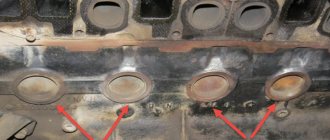
Often the gasket wears out between the communications through which lubricant and coolant circulate. As a result, mixing of such different compositions occurs and their mutual contamination. As a result, both of them noticeably lose their operational suitability. The following symptoms are typical for this failure:
- the oil becomes thinner (sometimes the level drops or rises);
- Antifreeze takes on a brownish tint.
Repair in this situation is urgently needed.
Another problem often encountered on 8-valve VAZ-2108 is a leak in the area between the coolant supply system and the combustion chamber. This happens in the following cases:
- insufficient tightening torque;
- uneven tightening of bolts;
- factory defective gasket.
Regardless of the reason, air is directed into the cooling circuit, which leads to heating of the antifreeze. An obvious sign of trouble is strong bubbling of the fluid in the distribution tank.
It is extremely rare to see damage to the gasket in the area between the cylinders. If this happens, then compression decreases, which leads to unstable engine operation.
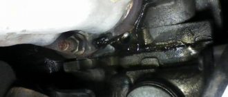
Often such problems arise a short time after replacing the cylinder head gasket. In this case, car owners spend a lot of effort trying to find the cause, and cannot even think that the named sealing element or incorrectly tightened head bolts are to blame. Therefore, knowledgeable craftsmen recommend first checking whether the joint between the cylinder head and the block is airtight. If characteristic streaks appear on the motor housing in the area of the head, then there is no point in looking further.
Preparing to remove the cylinder head
In order to install a new sealing element under the cylinder head of an 8-valve engine, it will have to be partially disassembled. First of all, remove the air filter - unscrew all the screws holding it in place and remove it.
If the VAZ has a carburetor, then this unit will have to be removed. Some people recommend leaving it in place, but in reality this is inconvenient and seriously complicates the work.
After dismantling the carburetor, the fuel pipes are disconnected from the cylinder head. Next, you need to unscrew the distributor - it is held in place by one nut. The assembly along with the wiring is removed to the side. If the fasteners are rusty or stuck, do not try to tear them off by force - spray with WD-40 and wait 5 minutes.
Next, proceed to drain the coolant. It’s worth talking about this point in more detail. Proceed like this:
- place the car on a pit or ramp;
- remove the mudguard from the engine;
- place a container (about 10 liters) under the radiator drain;
- screw the plug there;
- open the distribution tank.
When the antifreeze leaks out of the radiator, it is also drained from the cylinder block. It has a separate plug. Place a container under it and unscrew it with a key. Upon completion of the procedure, return all plugs to their place.
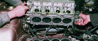
Removing the cylinder head - key points
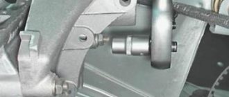
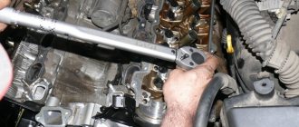
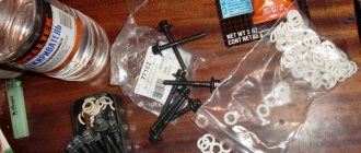
Now it’s the cylinder head’s turn. First, use a socket wrench of the appropriate size to remove its casing. Place the removed nuts and washers so as not to lose them. In addition, to gain access to the head, the timing chain must also be disconnected. Carefully loosen the tensioner and remove it completely after unscrewing the gear. To prevent the chain from slipping off the last one, it is tied together with any soft wire.
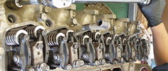
Next, the camshaft is disconnected - it is attached in nine places. If the tightening is too strong, then use WD-40 again.
After dismantling the shaft, remove the fuel supply hose and exhaust manifold from the cylinder head. We will not dwell on this point - everything is simple here.
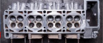
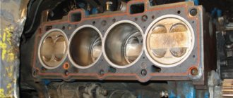
Now unscrew the head bolts - there are 11 of them (one is in the lower left corner on a separate “ear”). If the cover is stuck to the gasket, carefully pry it off using a long screwdriver as a lever (rest it on the pipe leading to the manifold).
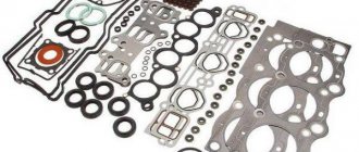
Replacing the gasket
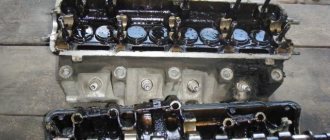
There are a few things to consider when replacing the gasket. So, if the cylinder head is dismantled for another need, then it will have to be changed. The old one cannot be used in the future. The new one, fortunately, is inexpensive.
After removing the worn seal, the surface located under it must be thoroughly cleaned. It is important to work carefully so as not to leave scratches. It will not be superfluous to sand the area with fine-grained sandpaper. Be sure to degrease the surface and remove all debris - even a small grain will not allow you to achieve a tight seal even with the most correct tightening.
Check the functionality of the valves of your VAZ car. If necessary, replace the seals in them. Then put the gasket on and put the head back in place.
Comments
Tightening the cylinder head bolts must be done in a strictly defined order - this is necessary for its correct mating with the cylinder block, so that excessive metal stress and distortions do not occur.
Cylinder head tightening diagram for VAZ cars (classic)
Tighten in 2 passes.
FIRST: tighten bolts 1 to 10 - tightening torque 3.5 - 4.1 kgcm.
SECOND: tighten the same bolts again - tightening torque 10.5 - 11.5 kgcm.
AFTER TWO APPROACHES, tighten bolt number 11 - tightening torque 3.5 - 4.0 kgcm.
Scheme for tightening the cylinder head on VAZ 2108 cars | VAZ 2109
Tighten in 4 passes.
FIRST: tighten bolts 1 to 10 - tightening torque 2.0 kgcm.
SECOND: tighten the same bolts again - tightening torque 7.5 - 8.5 kgcm.
THIRD: tighten all bolts 90°.
FOUR: re-tighten all bolts 90°.
Cylinder head tightening diagram on 16 valve VAZ engines
Tighten in 3 passes.
ONE: Tighten all bolts using a torque of 2.0 kgcm.
SECOND: tighten all bolts 90°.
THREE: re-tighten all bolts 90°.
Important! On 16 valve engines, it is permissible to use the cylinder head mounting bolts a second time, but only on the condition that their length without the head is NOT more than 95 mm, otherwise the bolt must be replaced. You need to measure the length using a washer.
How to make sure that the bolt is tightened properly?
When tightening a bolt, once the metal has reached its "yield point", the tightening torque will remain constant. This will show the torque wrench.
When should a bolt be replaced?
If the tightening torque has already been increased to 20 kgcm, but the bolt cannot be tightened, it means that it is too strong, and this bolt needs to be replaced. If the bolt does not turn and the tightening torque is constantly decreasing, then this bolt must also be replaced.
The procedure for tightening the cylinder head on a VAZ model 2108
Finally, we’ll talk about the intricacies of proper tightening. When the cylinder head is in place, tighten all the bolts with your fingers and be sure to tighten them completely. This can be done in any convenient order - it is important not to displace the cylinder head and gasket.
For the next stage of work you will need a torque wrench.
Stand on the side of the car so that the cabin is on your left, and proceed in the indicated sequence.
The correct tightening torque at the first stage is from 3.5 to 4.1 kgf m. In the second circle, the indicator rises to 10.5-11.5 kgf m. Now all that remains is to tighten the 11th bolt. For him, the standard force will be from 3.5 kgf m to 4.
Next, wait 20 minutes and, maintaining order, turn all the fasteners 90 degrees, and then repeat this action again. Then reassemble the engine and check its performance.
Camshaft installation
The shaft installation process occurs in the reverse order using the same tools as for its removal. Additionally, you will need a torque wrench that can be used to control the tightening force. The work is carried out as follows:
- Before installing the part into the body, lubricate the support journals, bearings and cams with clean engine oil.
Installation by marks
Upon completion of the replacement, it is necessary to align the camshaft and crankshaft to the marks. Only after such a procedure will the ignition timing be correct and engine operation stable. An additional tool you will need is a wrench to rotate the crankshaft, and the work itself consists of the following steps:
- We put the RV sprocket in place and tighten it, but not completely.
- We tighten the chain. To do this, unscrew the tensioner nut, turn the crankshaft a little, and then tighten the nut back.
- We turn the crankshaft with a wrench until the mark on the pulley is positioned opposite the length of the mark on the timing cover.
When reinstalling the valve cover, I always pay attention to the condition of the gasket, even if it has recently been changed. There should be no tears, strong pressing or other damage on it.
In addition, the seal should not be “oak”, but elastic. If the condition of the gasket leaves much to be desired, I always replace it with a new one, thereby eliminating possible oil leakage in the future.
Adjustment of valves
It is recommended to adjust the valves on the “classic” every 30 thousand km. mileage or after engine repair. Tools you need to prepare:
- open-end wrench for 13 and 17;
- probe 0.15 mm.
The work is carried out on a cooled engine after removing the valve covers and tensioning the chain:
- We combine the crankshaft and camshaft marks with the marks, which corresponds to the top dead center of the fourth cylinder.
- We check the clearance of valves 6 and 8. To do this, insert a feeler gauge between the cam PB and the rocker. If it fits in without effort, the gap needs to be made smaller. If it fits tight, then more.
Table: procedure for adjusting cylinder head valves on a “classic”
| Crankshaft rotation angle, o | Camshaft rotation angle, o | Cylinder numbers | Adjustable valve numbers |
| 4 and 3 | 8 and 6 | ||
| 180 | 90 | 2 and 4 | 4 and 7 |
| 360 | 180 | 1 and 2 | 1 and 3 |
| 540 | 270 | 3 and 1 | 5 and 2 |
Video: adjusting valves on a VAZ 2101–07
Some car enthusiasts use a narrow feeler gauge from the kit to set valve clearances. I would not recommend using it for the procedure in question, since if the valve lever is skewed, and the rockers can be skewed even with normal springs and good condition of the valve, a narrow feeler gauge will not allow for precise adjustment. And it’s more convenient to set the gap with a wide feeler gauge.
Replacing the camshaft on a VAZ 2106 does not require the owner to have high qualifications or special tools. Repairs can be carried out in a garage with a regular car set of keys and screwdrivers. If you follow the step-by-step instructions, the procedure will take about 2-3 hours, after which the gas distribution mechanism of your car will work clearly and smoothly.
In what cases is tightening needed?
Most domestic drivers do not understand for what purpose this procedure needs to be performed, what order must be followed and what the tightening torque should be. However, every driver should know that incorrect actions during this process can damage the cylinder block. Accordingly, this procedure should be treated with all care and responsibility.
Just a few years ago, vehicle manufacturers were required to tighten the cylinder head bolts during the first maintenance of the vehicle. But now this need has disappeared and now it falls entirely on the shoulders of the drivers. If you are the owner of a VAZ 2108, then this procedure should be carried out from time to time. In what cases is it needed:
- If an oil stain appears in the place where the cylinder head connects to the block itself. This indicates a leakage of consumable fluid, which can be a consequence of both wear of the gasket itself and loosening of the pins.
- If you have done engine repairs. Sometimes even qualified specialists can make such mistakes. Therefore, the owner of a VAZ 2108 may find this information useful.
- For verification purposes. Experienced car enthusiasts recommend tightening the bolts at least every 2 thousand kilometers. In practice, there are cases when during the operation of the VAZ 2108 the pins loosen on their own.
Thus, if you notice a leak of engine fluid in the place where the head connects to the cylinder block, first of all you need to check the tightening torque of the pins.
How to use a torque wrench, video instructions
Conclusions: • A university degree is not required to use a torque wrench. It is enough to understand the quantities in which torque is measured. • Even the most inexpensive model is enough to perform most jobs in your own garage.
Hi all! Lately I haven’t had any time to write on the blog; I’m actively engaged in diagnosing gasoline engines. After watching Pakhomov’s video courses and an in-depth study of the material part of cars, many hitherto uncertainties when repairing car injection systems dissipated and there was a desire to apply knowledge in practice.
I don’t want to seem boastful, but the results are already there and I think they’re good for a start. Sorry for this slight digression from the topic. Today we’ll talk about the topic of torque wrench. What is it and what is it eaten with?
Using a torque wrench
It's no secret that all bolted connections must be tightened to a certain torque. In the literature it is often referred to as newton times a meter. N*m. For example, 10 N*m means that the bolt or nut is tightened with a torque of 10 newtons applied to a 1 meter long arm.
Why do you need to tighten bolted connections to a certain torque? Well, firstly, so that the connection is strong and spontaneous unraveling does not occur. Secondly, when over-tightened, the threads break.
A reader recently sent me an email and asked questions: “How to choose a torque wrench for a car?” and “How to use a torque wrench?” I will answer these questions. But first, let's get acquainted with the types of torque wrenches.
Today there are three types of torque wrenches known. First type.
Pointer torque wrench
This wrench has a handle with a scale, a 1/2-inch square with a ratchet mechanism, and an arrow. The torque wrench scale is marked in N*m or kgf*m in both directions. There is zero in the center of the scale and the arrow of the torque wrench initially points to it. The key handle has a fine knurling for easy holding. This key works on a very simple principle. When the bolt connection is tightened, the metal handle bends (spring steel) and the arrow fixes this bend relative to the scale zero. Everything is very simple.
Procedure and diagram
We advise you to tighten the torque of the screws if you have ever encountered such a process. The following will describe the general procedure for the Lada 2108, but it should be noted that each engine has its own operating nuances that need to be taken into account.
Necessary tools
You will need a torque wrench for this procedure. This tool is needed specifically for tightening screws and determining torque. It can be purchased at any specialized store, and its price fluctuates around 1,300 rubles (approximately 400 hryvnia).
Sometimes so-called “masters” say that it is not necessary to use a torque wrench for this procedure. They say that an ordinary wrench will work just fine, and in general, you can tighten the screws “by eye.” Naturally, it will be possible to tighten the screws, but it will be incorrect, and later this may cause other problems.
Stages
If you feel that the quality of the head screw is poor, then do not even try to tighten it. Replace it immediately to protect yourself from possible problems. In addition, before the actual procedure, you should check the quality of the thread. It is also advisable to lubricate it. Do not forget that reusing spring parts is unacceptable, since in this case you will not achieve normal tension.
The stages of tensioning the pins on the Lada 2108 are similar to those performed on classic car models. The diagram is provided below. The process itself should begin with the central bolts. It takes place in four steps.
Diagram of the order of tension of the cylinder head pins Tightening the cylinder head pins of the VAZ 2108
- Using the above tool, all cylinder head bolts must first be tightened to a torque of 2.0 kgf*m. First, the two middle elements are tensioned, then the two lower and two upper ones, which are located on the sides of the middle bolts. Then you need to tighten the two leftmost and two rightmost screws, starting with the bottom ones. The order should be exactly like this. The numbers on the diagram indicate the order of the components.
- Then, in the same order, using the same tool, you need to tighten the components with a torque of 7.5 - 8.5 kgf*m.
- After this, all pins must be tightened 90 degrees.
- Then they should be turned again, again by 90 degrees.
How to get to the camshaft?
To get to the VAZ 2109 camshaft, you will need to dismantle several parts. Arm yourself with the following tools:
- hexagon;
- wrench 13 or similar with a socket head;
- replaceable head for 10;
- ratchet handle.
To start work, turn off the power to your “nine” by disconnecting the battery. Then you need to set the piston of the first cylinder to the top dead center position.
Now we dismantle the devices that will interfere with the work in the following order:
- Air filter.
- Gasoline pump.
- Distributor.
- Let's take care of the gear. Remove the timing belt from it and assess its condition. Installation of a split gear will only be necessary if the old one has visual defects: chips, damage, deformation. If everything is in order, simply remove it by unscrewing the fastener. Don't forget to pick up the key so you don't lose it.
- Remove the drive housing on which the distributor is located.
- Now the path to the camshaft housing is clear.
- Remove all body fasteners, there are 10 of them in total.
- Next, pull out the fastening studs. Once all the pins have been removed, the housing can be removed.
- And here is the camshaft. Now he can be taken out of bed and examined.
The VAZ 2109 camshaft will need to be replaced if it is bent or the cams are damaged. A new one will cost about 1000 rubles. The camshaft is installed in the reverse order. Follow the order of tightening the bolts on the body so that part of the assembly is assembled normally and all parts take their position. More specific information on how to tighten can be found in your vehicle's owner's manual.