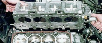
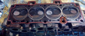
The cylinder head (cylinder head) is one of the most important components of the engine. The head of most modern engines contains a gas distribution mechanism, a partially manufactured combustion chamber, and channels for the lubrication and cooling systems through which working fluids circulate. In the event of certain malfunctions, it may be necessary to remove the cylinder head both to repair the head itself and the mechanisms inside it, and to gain access to parts and elements in the cylinder block (for example, the CPG).
We also recommend reading the article on how to properly tighten the cylinder head bolts when installing them on the engine. From this article you will learn about the features and sequence of tightening the cylinder head bolts, as well as various nuances when performing this procedure yourself.
The reasons why you have to remove the head can be different. Quite often, the cylinder head is dismantled as a result of engine overheating, in case of need to replace the cylinder head gasket or repair the timing belt. A frequent reason for removing the head is also the appearance of cracks in its body or the appearance of other defects. In such situations, the block head is removed for diagnostics on a test stand and then repairs are carried out. Quite often, engine modifications during minor tuning or deep boosting of the engine involve dismantling the cylinder head. Please note that this operation is considered quite serious and requires certain skills and special equipment. For this reason, we intend to further talk about how to remove the cylinder head yourself and do it correctly.
When is it necessary to repair the head?
Work on dismantling, repairing and installing the cylinder head in a car may be required for the following malfunctions:
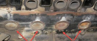
- A white emulsion forms on the dipstick for diagnosing the level of motor fluid or under the plug for filling it. This indicates a breach of the cylinder head gasket or damage to the head housing (cracks) and refrigerant entering the lubrication system. The emulsion may be barely visible.
- Thick, white smoke began to come out of the car's muffler; drops of liquid could break out when the power unit was running. Most likely, this is a coolant and its entry into the exhaust system is associated with damage to the cylinders. The antifreeze level will be reduced, and the appearance of steam may be caused by overheating of the internal combustion engine and increased condensate content. But if white smoke comes out constantly, this indicates a broken cylinder head gasket.
- Oil stains or a greasy film have appeared on the surface of the antifreeze in the expansion tank; its presence may appear in the radiator unit. Engine fluid could get into the cooling system through cracks in the gasket or the block head itself. The exception is cars whose owners flush the cooling system with used motor fluids. Of course, this cannot be done.
- Small bubbles may get into the neck of the radiator device. This indicates that exhaust gases from the exhaust system flow from the combustion chamber into the cooling system. There is damage or a defect somewhere, most likely in the gasket itself or on the structure of the block head. If bubbles form when replacing consumables, this is normal. But if their formation is observed regularly, diagnostics of the power unit is required.
- Exhaust gases escape through a damaged gasket in the cylinder head. This problem is rare, but can be easily diagnosed. You just need to take a closer look.
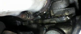
- Engine fluid began to leak from under the cylinder head gasket. The problem may be poor tightening of the head screws. This procedure must be performed in a certain sequence, otherwise you can strip the threads and break the studs. The tightening process must be done using a torque wrench.
- If there is a gasket breakdown or the head is damaged directly between the cylinders, it will be difficult to determine. Signs of such a malfunction include an increase in fuel consumption and a drop in power of the power unit. The problem may be accompanied by a decrease in compression in one or more cylinders, usually this occurs in neighboring devices.
The “ICE Theory” channel spoke in detail about the need to repair the cylinder head.
Diagnostic methods
When direct or indirect signs are detected, a new task arises for the car owner. He needs to figure out how to check the cylinder head gasket for a breakdown.
There are several methods in total. Moreover, the diagnostics are quite simple and can be used in garage conditions. Experience does not play a key role here, since even novice motorists can cope with the task.
If you are interested and need to know how to check whether the cylinder head gasket on a car engine has been broken, perform the following manipulations. Any of the presented methods is suitable for obtaining an accurate answer regarding the integrity and current condition of the seal between the block and the head.
- Visual inspection. The simplest option is how you can determine for yourself that the cylinder head gasket on the engine is broken or worn out. There is no specific and strict algorithm of actions here. The malfunction is determined simply by visual observation. First you need to start the engine, open the hood and take a closer look at the area where the block and head connect. If even a small amount of smoke comes out through the cracks, there is a problem. You can also listen to the behavior of the motor, which may begin to produce uncharacteristic ringing sounds.
- Checking the radiator and coolant expansion tank. It is also necessary to check the neck, with the help of which new engine oil is filled as part of scheduled maintenance. The method is also visual. Just unscrew all the caps and look at them carefully. Don't forget to look inside the tank. If coolant has penetrated into the engine, you will see a characteristic red emulsion on the oil filler cap. If the oil is in the antifreeze, then oily spots will appear on the radiator cap or expansion tank.
- Exhaust pipe monitoring. Start the engine. You can ask an assistant to rev the throttle a little to increase the volume of smoke coming out of the exhaust pipe. If you see white smoke coming out, which is actually steam, there is probably a problem with a broken gasket. When using antifreeze, white smoke with a characteristic sweet tint usually comes out of the pipe. Additionally, look into the coolant expansion tank. If the level gradually drops, then you have probably diagnosed a gasket failure. Although the sign is considered indirect.
- Checking the presence of exhaust in the cooling system. To do this, you can use one of 2 methods. The first method involves unscrewing the cap on the radiator or expansion tank. If there is active seething inside, this is a bad sign. The second method is to use a balloon or a regular condom. The product is pulled onto the neck of the tank, having first removed the lid. Then the engine starts at a speed of about 3-5 thousand per minute. If the balloon or condom inflates (quickly or slowly), a leak has occurred. This means that the gasket will need to be replaced in the near future.
All methods have been used for decades, but continue to be effective, simple and quite accurate. Yes, you can spend extra money and go to a car service for diagnostics. But in order to save money, it is better to determine the fault yourself, and then entrust the replacement to specialists or do everything yourself.
Replacing the gasket yourself is potentially complex and difficult to do without the appropriate experience and special tools. Also, you should not trust garage service stations that do not have a license. Here it is better to spend more money, but put the car in the safe hands of specialists who will provide guarantees for the work performed.
Causes of defects
The purpose of the head is to form a combustible mixture of air and fuel, which is created in the combustion chambers. It is used to ignite and propel the vehicle. The cylinder head, like any other machine component, is not immune to defects. Malfunctions can occur spontaneously or as a result of a traffic accident or wear and tear of the unit.
All failures are associated with:
- defects in the production of the cylinder head;
- high load on the node;
- incorrect or insufficient maintenance;
- poor quality lubrication of the internal components of the device;
- lack of protection against freezing or corrosion in the refrigerant circuit.
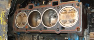
Cylinders and honing
The working cylinders can be made directly as part of the block, or sleeves can be used. A special nickel-silicon alloy, Nikasil, is applied to the surface of the cylinders. This is a very durable material that protects the piston rings from friction. The surface is polished to a mirror finish to minimize friction when oil supply is limited.
Cylinder hone
Honing is used to improve lubrication of the inner surface of cylinders. Hone is applied with a special tool with a head and abrasive stones. As a result, an engraved mesh is formed on the surface. Its grooves hold oil better. An oil film forms on the inner walls with the hone, resulting in a significant reduction in friction and an increase in the service life of the parts. Re-honing is usually done during engine boring or liner replacement.
What is needed to replace the cylinder head?
It is necessary to disassemble, replace and restore the cylinder head on an 8-cylinder or other engine after preparing the tools:
- a special mandrel will be required for pressing oil seals;
- micrometer, necessary for measuring valves, as well as guide elements;
- reamer, will be used to unfold new bushings;
- special mandrels for dismantling (pressing out) and installing new bushings;
- a set of countersinks, designed to restore valve seats;
- special devices for desiccation of valve spring elements;
- set of wrenches;
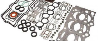
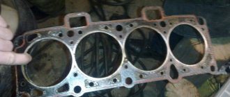
- new cylinder head gasket;
- an electric stove is used to heat the cylinder head if it is to be troubleshooted, as well as to warm up the bushings before pressing.
Before repairing the cylinder head, it is imperative to prepare the necessary spare parts and tags; their composition depends on the car model and the type of defect.
User Alex ZW talked about repairing the cylinder head, as well as what is required to complete this task.
Symptoms of a problem
Experienced people can quickly identify a cylinder head gasket failure. This can be understood by several characteristic symptoms. They depend on where the damage occurred and how severe it is.
Knocks out coolant
If there is damage between the combustion chamber and the channel through which the coolant passes, hot gases from the cylinder will enter the coolant system. Because of this, a very high pressure is created in it, which squeezes out the air along with the liquid through the plug valve installed on the expansion tank. When the valve fails, the pressure swells and ruptures the rubber hoses. Or gasket damage increases and gases enter the lubrication system.
It's easy to check: remove the cap from the tank and start the engine after that. Bubbles along with liquid will come out of the neck. Do not unscrew the plug while the engine is running, as excess pressure will forcefully push the coolant and hot steam out and cause burns.
Cold air from the heater
This option appears on some car models. If the plug does not have time to release excess pressure, then air accumulates in the heater radiator (the highest point of the system), which is why only cold air comes out of it at any setting.
To determine whether the cylinder head gasket is broken, you need to run the heater at the highest temperature and remove the pipe at the outlet of the heating radiator. When the coolant flows, quickly put on the pipe and tighten it. If after a certain period of time the heat disappears, most likely the problem is in the gasket.
Engine temperature surges
When gases enter the coolant, they can accumulate in front of the thermostat, since it does not release liquid. Because of this, heat transfer is disrupted and the unit operates with a noticeable delay, and the temperature rises noticeably higher than usual.
After opening the thermostat, the temperature readings are normalized, after which the process is repeated again. Therefore, jumps are observed constantly, there is no normal temperature regime. Over time, the problem may get worse.
For your information!
To find out for sure that the gasket is to blame and not the thermostat, you need to look into the expansion tank. There will be a lot of air bubbles there.
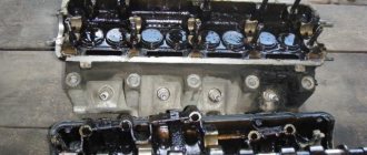
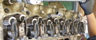
Removing the cylinder head
To repair the unit, you will need to remove it from its seat. The procedure for removing the cylinder head may have certain nuances depending on the type of device and car model.
A universal algorithm of action when dismantling the unit is considered:
- First, the wire with the negative terminal is disconnected from the battery.
- The piston of the first cylinder is installed in the position of the top dead center of the compression stroke. All refrigerant is drained from the cooling system; a container is first installed under the drain hole to collect the liquid.
- Then you need to reduce the pressure level in the power system. This is done if the cylinder head is dismantled after a trip. The intake line connecting the muffler to the exhaust manifold device is disconnected from the exhaust pipe. The procedure is performed differently depending on the vehicle.
- Then you need to remove the cylinder head cover.
- The connector with wires is disconnected from the mass air flow controller. The clamp that secures the air outlet line to the throttle device is loosened. Then, a hose equipped with an air filter element housing and an air intake pipe is dismantled from the assembly itself.
- The nut securing the bracket for the supply line of the water pumping device is unscrewed. Then a wrench is used to loosen the nut that secures the supply line bracket to the exhaust manifold assembly. The bracket itself is moved to the side, the clamps are loosened and the two cooling system pipes are disconnected from the throttle assembly. We are talking about inlet and outlet lines.
- Using a screwdriver, loosen the clamp that secures the vacuum brake booster pipe to the valve on the receiver. The highway itself is being dismantled. It is necessary to turn the sector of the throttle valve drive device all the way. The drive mechanism of the mechanism is disconnected from it.
- Unscrew two nuts that secure the tips of the negative conductors to the rear cylinder head cover. The cables are removed directly from the studs. Then you need to unscrew the nut that secures the lower fastening of the left strut and the bolt of the lower fastening of the right strut.
- Using a wrench, unscrew the nuts of the upper clamps of the intake manifold struts on both sides. The elements themselves are dismantled.
- The connector with wiring from the engine fluid level controller in the crankcase of the power unit is disconnected. You also need to disconnect the pads from the throttle position controller, the idle speed sensor of the injector wiring harness, and the coolant temperature controller. Then the wires from the crankshaft position regulator and the engine knock control device are disconnected. The blocks with cables are disconnected from the coolant temperature volume controller in the engine, as well as the engine fluid pressure sensor.
- Then you need to disconnect the tips of the high-voltage cables connected to the spark plugs. The harness with conductors is removed from under the receiver. Unscrew the three bolts that secure the front cover of the camshaft drive belt. Then this element is dismantled along with the belt. The procedure for removing the product depends on the vehicle. If the belt is worn out and shows signs of damage and defects, it must be replaced.
- To secure the camshaft toothed disk from turning, it is necessary to unscrew the screw that secures the pulley to it. The bolt is removed together with the washer. The pulley is removed from the camshaft. When carrying out this task, you must be careful not to damage the seal of the assembly. If during the process it was noticed that the key is not installed tightly in the groove of the so-called bridge, then it must be dismantled so as not to be lost.
- The nut that secures the rear part of the camshaft drive device to the upper component of the head is unscrewed. Four more screws are unscrewed, three of which secure the oil pump device, and the rear cover is dismantled. Then use a wrench to unscrew the nut that secures the mass cable. The conductor is removed from the pin that secures the exhaust line of the cooling system to the cylinder head.
- The clamps are loosened and the supply hose of the radiator unit, as well as the throttle tube and the heating system, are removed from the outlet line. The thermostat with the connected pipe is turned off. The nuts securing the fuel drain and supply lines are unscrewed, and the hoses must be secured with a wrench so that they do not turn. There are sealing elements on the fuel pipes; after disconnecting each pipe, they must be removed.
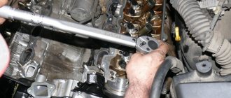
- It remains to loosen the bolts that secure the cylinder head to the engine. They are unscrewed in a specific sequence prescribed by the manufacturer. More details about this can be found in the service manual. After loosening, the bolts are completely unscrewed and removed along with the washers, and the cylinder head is dismantled.
Removing the air filter housing with air intake pipe
Disconnecting the cooling system pipes from the throttle assembly
Disabling the thrust of the throttle valve drive device
Disconnecting the connector with wiring from the engine fluid level controller
Removing the belt from the camshaft drive
Unscrewing the bolts to remove the cylinder head from the car
Before the camshaft drive belt is installed, the crank and camshaft pulleys are not allowed to be turned.
Basic recommendations
First of all, it should be noted that such a procedure can be carried out after repairing the power unit or in order to check the tightening torque of the bolts during engine operation. If the cylinder head has been dismantled, you should carefully inspect the bolts, as well as the holes in the cylinder block for their installation. Screws must not have elongation or deformation of the threaded part. The holes in the block for the bolts are cleaned of any remaining engine oil, liquid, or other foreign particles. If this is not done, the cylinder block may be damaged, and the cylinder head will not be able to be tightened with the required force.
This is interesting: Causes of black spark plugs: carburetor, injector
Work should begin only after reading the vehicle manufacturers' recommendations for operation and repair. There the driver will find all the necessary information to complete the job, including the forces and sequence of tightening the bolts.
Another feature of using such bolts is their installation at a certain angle. To do this, you will need a special key with an indicator that will show the degree of inclination.
User Igor Ivanov shows in the video the installation and tightening of the cylinder head.
Bolt tightening torque (force)
The tightening torque for the bolts is different for each car (due to design features). Each vehicle has its own table of fastener tightening torques. In the next section, we will consider the cylinder head fastening forces using the example of a VAZ head.
Table: tightening torques for connections depending on thread diameter
| Nominal thread diameter | Turnkey size of head, bolt (nut), mm | Thread pitch, mm | Strength classes according to GOST 1759–70 | ||||
| Bolt | |||||||
| 5.8 | 6.8 | 8.8 | 10.9 | 12.9 | |||
| screw | |||||||
| 6 | 10 | 1 | 0,5 | 0,8 | 1,0 | 1,25 | 1,6 |
| 8 | 12 — 14 | 1,25 | 1,6 | 1,8 | 2,5 | 3,6 | 4,0 |
| 10 | 14 — 17 | 1,25 | 3,2 | 3,6 | 5,6 | 7,0 | 9,0 |
| 12 | 17 — 19 | 1,25 | 5,6 | 6,2 | 10,0 | 12,5 | 16,0 |
| 14 | 19 — 22 | 1.5 | 8,0 | 10,0 | 16,0 | 20,0 | 25,0 |
| 16 | 22 — 24 | 1,5 | 11,0 | 14,0 | 22,0 | 32,0 | 36,0 |
| 18 | 24 — 27 | 1,5 | 16,0 | 20,0 | 32,0 | 44,0 | 50,0 |
| 20 | 27 — 30 | 1,5 | 22,0 | 28,0 | 50,0 | 62,0 | 70,0 |
| 22 | 30 — 32 | 1,5 | 28,0 | 36,0 | 62,0 | 80,0 | 90,0 |
| 24 | 32 — 36 | 1,5 | 36,0 | 44,0 | 80,0 | 100,0 | — |
Correct tightening order
There is a certain order for tightening the bolts; it is the same on almost all cars - from the center of the head to its edges, cross to cross. So, for example, the two central bolts of the right and left rows are tightened first, then the two bolts located to the left of the central ones, then the two to the right of the central ones, then the two bolts located on the left in both rows, and the bolts located on the right in both rows complete the order.
It is important to remember that fastening is always performed in three to four approaches:
- The first approach is a force of 3-4 kgf.
- The second approach is a force of 7 kgf.
- The third approach is a force of 9 kgf.
- The last approach is a force of 11.5 - 12 kgf.
Some nuances
The tightening torque is one of the main factors for the normal fit of the block head. But this criterion is influenced not only by the applied force, but also by the fasteners themselves:
- General condition of the bolts – new or used;
- Presence of lubricant on the threaded part;
- Thread condition.
The type of power plant (petrol, diesel), as well as the number of valves, does not affect the cylinder head tightening technology. But this does not mean that the force and tightening procedure are identical for all motors, and before seating the head, you should definitely study the conditions for performing the operation and all its features.
Errors when installing the head
If you do not use a torque wrench when installing the cylinder head, you may make a mistake with the force, which will lead to uneven torque. In such cases, there will be excessive or insufficient force, which will result in either deformation of the head surface or allow the breakthrough of gases, oil or coolant. In both cases, this is fraught with serious consequences for the engine.
If you follow the rules for tightening the fastening bolts, as well as the required torque, you can always count on reliable and durable operation of the installed parts. The gas distribution mechanism in the engine plays a major role, so you should not neglect the rules for installing the component elements.
DIY cylinder head repair
To carry out repairs, you will have to disassemble the cylinder head. Conventionally, the diagnostic and troubleshooting procedure can be divided into several stages.
First stage
Checking and repairing the cylinder head at the initial stage is carried out as follows:
- The two fastening nuts are unscrewed and the device is dismantled. The nut securing the bracket for the supply line of the water pump mechanism is unscrewed several turns. The bolt that secures the fuel pipe holder is removed, and the device itself is removed. Then you need to unscrew three more nuts that secure the receiver device, as well as two that secure the bracket. The latter is removed after the actions are completed.
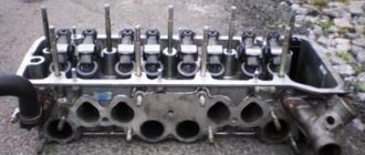
- It remains to unscrew two more nuts that secure the receiver; a wrench is used for this. The tightening of the nut for fixing the bracket of the receiver device is loosened. The unit itself is then dismantled. The nuts securing the bracket and the intake manifold are unscrewed, and both parts are removed. You also need to unscrew the fastenings of the exhaust manifold device and dismantle the unit.
- Carefully remove the two gaskets on the intake manifold and exhaust manifold. These items must be replaced even if their condition is generally satisfactory. Then the cylinder head must be placed so that the housings of the bearing elements are directed upward. Wooden spacers are pre-installed under the assembly, this prevents damage to the valves.
- Two nuts, as well as a screw that secures the rear cylinder head cover, are unscrewed, after which it is removed. There is a rubber seal under the head of the fastening element. Using a spark plug wrench, unscrew the spark plugs. Then you need to evenly unscrew the ten nuts securing the fastenings of the front and rear housings of the camshaft bearing elements. The washers, as well as the housings themselves, are dismantled.
- If the key in the camshaft groove is not installed tightly, it must be removed. Then the timing pulley block is dismantled from the cylinder head, and the oil seal is removed from the assembly. The valve pusher elements with adjusting washers are removed. After removing the next pusher, it is necessary to mark each element and the washer that secures it with numbers. This will avoid mistakes during further installation. There is no need to remove shims from devices unnecessarily.
- The combustion chambers are cleaned from traces of carbon deposits, for this you can use acetone or fuel, the residues are subsequently removed. A visual diagnosis of the cylinder head is performed. If there are defects in the form of cracks or traces of burnout in the chambers, the device is completely replaced; its repair is impractical. It is necessary to remove burrs if they are present on the surface of the cylinder head.
- The work plane, which is adjacent directly to the block, is diagnosed. To complete the task, you need to place the ruler edge-on on the surface itself and measure the gap, first along the diagonals, and then along. If the size of the play is more than 1 mm, the cylinder head is replaced with a new one. To diagnose the tightness of the device, you need to unscrew the two nuts that secure the exhaust line of the cooling system. The hose itself is then removed.
- Then you need to plug the hole in the engine cylinder head under the exhaust line. To do this, you can use a dry cardboard gasket, after installing which the fixing nuts are tightened.
- Then fuel or kerosene is poured into the channels of the water jacket. If the fluid level decreases after filling, this indicates the presence of cracks and the need to replace the cylinder head. When the diagnosis is completed, the cardboard gasket is removed.
- The condition of the bearing surfaces under the pulley journals on the cylinder head and bearing housings is diagnosed. If the inspection shows traces of defects or scoring as a result of wear, the head is replaced along with the bearings.
User Alexander Skripchenko in his video, using the example of a VAZ 2108 car, showed what mistakes should not be made when performing cylinder head repairs.
Second stage of repair
At the next stage of repair, the following actions are performed:
- The oil system channels are flushed. To perform this task, it is necessary to plug the hole located on the side of the combustion chamber; it is located between the third and fourth cylinders. Then fuel is poured into each channel; you need to wait about twenty minutes to remove contaminants. After this, the fuel is drained and the plug is dismantled. Then you need to finally flush the channels with fuel using a blower or compressor.
- To diagnose valve tightness, fuel or kerosene is poured into the combustion chambers. If within three minutes after filling the liquid does not leak out, then the valve elements are intact and do not need to be replaced. When the kerosene begins to come out, the parts are ground in.
- A support, for example, a bearing, is installed under the valve being dismantled. A device is installed to compress the spring elements of the parts, after which they are compressed. Using a screwdriver or tweezers, the so-called crackers are removed. Then the upper plate of the spring element, as well as the devices themselves, are removed. In the same way, crackers, springs and plates are removed from other valves.
- Then you need to mark the valve elements in accordance with the cylinder numbers. By pushing these parts from below, you need to remove them from the cylinder head. The valve stem seals are removed using pliers or a special device. Then the lower plates of the valve spring elements are removed. The latter are cleaned from traces of carbon deposits using a metal brush, after which they are visually diagnosed.
- Valves must be replaced if they have deep defects or scratches on the working surface. Devices with cracks, deformed rods, plates, or burn marks must be replaced. If the damage on the surface is shallow, then the situation can be corrected by grinding in. When this method does not solve the problem, parts are polished using a special machine. When performing this task, it is imperative to maintain the overall dimensions; each car manufacturer has their own.
- The condition of the valve seats is diagnosed. Their surfaces are not allowed to show signs of wear, corrosion, etc. Seats can only be replaced by specialists; if the defects are not serious, they are corrected by grinding in. Significant damage can only be removed by sanding. When performing a task, it is important to maintain the dimensions so that the ground devices can be used.
- At the next stage, the condition of the external and internal spring element of the valve is diagnosed. Parts must be replaced if they are worn, broken, bent or have cracks. To diagnose the elasticity of the external spring element, its height is measured, first in a free state, and then under load. The internal part is checked in the same way. If the checked elements do not meet the required values, they must be replaced.
The channel “ICE Theory” spoke in detail about the repair procedure and assembly of valve elements of the cylinder head.
Third stage
Algorithm of action when performing the final stage of diagnostics and repair:
- The valve pusher elements are checked. If there are defects in the form of scratches and burrs on the working surface of the device, they must be replaced. Damage to the adjusting washers is also not allowed. We are talking about wear, scratches, scuffing, etc. Otherwise, the parts must be replaced with new ones. On the surface of the washers there may be concentric marks of running-in, which appeared as a result of impact with the camshaft cams.
- The gaps between the valve elements and guides are checked. The nominal amount of play for inlet devices is from 0.022 to 0.055 mm, for inlet devices - from 0.029 to 0.062 mm. The value of the maximum permissible gap for both types of parts varies in the range of up to 0.3 mm. The backlash itself is directly defined as the difference between the diameter of the hole in the bushing and the valve element stem. It is better to carry out diagnostics in a workshop, since the test will require a special device - a bore gauge.
- If the gap is less than the maximum permissible value, then to eliminate it you can resort to replacing the device. Otherwise, you will have to change the guide sleeve. To perform this task, it is necessary to press out the defective element from the side of the combustion chamber; a special mandrel is used for this. Spare parts are supplied with bushings equipped with retaining rings. The outer diameter of such a part is larger, and the size of the hole for installing the valve element is smaller.
- The bushing is installed using the press-fit method from the camshaft side; it must first be treated with engine fluid. The part is installed until the lock ring stops in the cylinder head. The hole in the bushing is unfolded using a special reamer. For intake elements it must be increased to approximately 8.022-8.040 mm, and for exhaust elements - to 8.029-8.047 mm.
- If you are installing an old part, you must first remove burrs from its surface. After completing the task, grinding the valve element to the seat is required. The element is installed in the cylinder head, taking into account the previously indicated markings. Before installing the part, its rods must be treated with motor fluid. The lower plates of the spring elements are being installed.
- The oil seals are being installed.
- The camshaft is checked; this unit must be replaced if there are signs of wear on its journals or cam surfaces in the form of large marks or scuffs. In workshops equipped with specialized tools, it is possible to diagnose the radial runout of the camshaft journals; this value should be no more than 0.02 mm. It is also necessary to check the play between the support holes, as well as the pulley journals; this value will ideally be no more than 0.2 mm.
- The camshaft is installed together with the bearing element housing.
- A new cylinder head gasket, exhaust manifold, and intake manifold are being installed. Under the nuts that secure this hose and manifold, there are larger nuts compared to the other fastening elements.
The user Autoreanimator spoke in more detail about replacing and installing a new cylinder head gasket.
Method 5 – cylinder head bolt is broken
The method is suitable for cases where the bolt has burst and part of it in the form of a pin remains inside the cylinder block. We use welding, a tube, a nut.
Advantages of the method:
- there is no need to disassemble the engine;
- saves time.
Take a tube with the following diameters:
- The outer one is slightly smaller than the diameter of the cylinder head bolt.
- Internal – such that an electrode of 2–3 mm fits freely into the tube.
Weld a 17 - 19 nut onto one side of the tube.
- Insert the tube into the hole so that it touches the broken pin.
- Insert the electrode into the hole of the tube at a slight angle, so that its end is located where the edge of the tube touches the pin.
- Weld the tube to the stud.
- Use a wrench to unscrew the pin.
Another way if the cylinder head bolt breaks.
Suitable for cases where the broken pin is not deep, no more than 5 cm.
To unscrew the stud from the block, first use a drill and a long 10 mm drill bit. This will help you level and center its surface. Next, using a 4 mm drill, drill a hole in the stud with a depth of at least 1 cm.
Carefully drive a 25mm Torex key into the stud and use a lever tube to unscrew it. You need to unscrew without jerking, gradually increasing the force on the lever.
Installation of cylinder head
The cylinder head is installed in the reverse order. When performing the task, it is necessary to change the cylinder head gasket, even if it was in perfect condition when dismantled. When replacing or repairing the cylinder head, experts advise installing new bolts that secure this unit; this is due to the design features of the fastening elements. When tightening bolts, you cannot be guided by the principle - the stronger, the better.
The procedure for tightening the cylinder head bolts is individual for each individual car model.
The installation of all attachments, lines and pipes is carried out in accordance with the diagram drawn up by the car owner and the characteristics of the vehicle.
The process of tightening the bolts securing the cylinder head to the engine is described using the example of a VAZ 2109 car:
- At the first stage, the fixing elements are tightened with a force of 2 kgcm or 20 Nm. A torque wrench is used to measure the tightening torque.
- At the next stage, the force should be from 69.4 to 85.7 Nm. Or 7.1-8.7 kgms.
- At the third stage, all bolts are tightened to 90 degrees.
- At the last step, the fastening elements must be tightened again by 90 degrees.
After successful installation of the cylinder head, the unit is diagnosed for leaks; to do this, you need to start the engine. If the camshaft was replaced during the repair process, then the operation of the power unit must be started at low speeds.
Loading …
Preparing tools
Preliminary preparation of all necessary tools will save time when dismantling the mechanism. To remove you will need:
- Flathead screwdriver.
- Knife.
- Containers for coolant and engine oil.
- Wire cutters.
- Pliers.
- Hammer.
- Socket wrenches.
Experts also recommend having a torque wrench. The tool is mainly used only when installing the cylinder head, but sometimes it may be needed when removing it. Since all car models have their own characteristics, it is better to find a manual for a specific car in advance.
Stages of work
Removing the cylinder head involves carrying out preparatory work:
- First of all, you need to disconnect the terminal from the battery.
- If there is a decorative plastic cover, it must be removed. Also, if there is crankcase protection, it is better to remove it.
- Next, the liquids are drained into different containers, the pipes and other wires are disconnected. If it is recommended to drain the oil on a hot engine, then it is better to carry out the remaining actions when the engine has cooled down.
- For more free access to the engine, experienced technicians recommend removing the battery.
- The drive belt must be loosened and the power steering pump must be turned off. After loosening the belt, you can remove the bar that holds it, and move the generator to the side to increase the space around the engine.
- Since step-by-step compression, combustion, exhaust and intake of the gas mixture occurs in the cylinders, it is important to set the piston in a certain position. The TDC position is best suited for this purpose.
- Next, you need to unfasten the wiring harness and move it to the side.
- Removing the air filter. In addition to the filter itself, it is necessary to remove its housing and timing belt. Once the belt is removed, you need to begin dismantling the camshaft pulley. The pulley must be secured with one screwdriver to prevent rotation, and the part must be removed with the second.
- The idle air control and throttle control connectors must be disconnected from the electrical wiring.
- The air pipe that supplies gas must be disconnected from the TPS and dismantled.
- The solenoid valve is disconnected from the system and fixed in a safe place.
- Next, you need to disconnect the hoses responsible for the fuel supply.
- All sensors are turned off, and the remaining pipes are removed and stored in a safe place.
- After all the hinged parts have been completely dismantled, you can begin to dismantle the armored wires and move them to a separate place.
- Next, the bolt is unscrewed, which is responsible for holding the intake pipe bracket. The top bolts can be unscrewed using a socket wrench.
- Next, the receiving pipe is detached from the manifold.
The next step is to unscrew the fasteners that secure the head directly to the cylinder block. It is better to unscrew the bolts gradually. The first two times, unscrewing occurs only half a turn of the thread.
All fasteners must be removed evenly, so it is better to use a torque wrench. The sequence must be followed exactly to prevent deformation of the motor. You can find out the sequence of unscrewing in the manual supplied with the car.
After the bolts have been unscrewed, the cylinder head is dismantled. Depending on the manipulations that will be carried out with the cylinder head, the part can be dismantled complete with the exhaust manifold and intake pipe.