Relay breaker for hazard warning lights and direction indicators
Rice.
8.33. Scheme for switching on the hazard warning lights and direction indicators on VAZ-2106 cars: 1 – sidelights; 2 – side direction indicators; 3 – battery; 4 – generator; 5 – ignition switch; 6 – main fuse block; 7 – additional fuse block; 8 – relay-breaker for alarm and direction indicators; 9 – control lamp for direction indicators in the speedometer; 10 - alarm switch; 11 – rear lights; 12 – direction indicator switch in a three-lever switch Relay-interrupter 8 (Fig. 8.33) is designed to receive an intermittent light signal from the direction indicators both in the emergency signal mode and in the turn indication mode, as well as for monitoring the serviceability of the direction indicator lamps. If the lamps are working properly, then in the turn indication mode it creates a flashing warning lamp 9. If the lamps are faulty (burnout or break in the lamp circuit), then the breaker relay ensures that the warning lamp is constantly lit.
The breaker relay is mounted under the instrument panel on a bolt welded to the wall of the air supply box. A faulty breaker relay cannot be repaired and should be replaced with a new one.
The breaker relay must ensure blinking of the direction indicator lamps with a frequency of 90 ± 30 cycles per minute at a rated load of 92 W, an ambient temperature of -20 to +50 ° C and a voltage of 10.8 to 15 V.
Rice. 8.34. Scheme of the relay-breaker for the alarm and direction indicators 23.3747
Until 1985, a relay-interrupter of type 23.3747 (Fig. 8.34), assembled on integrated circuits, was used. Since 1985, a relay-interrupter 231.3747, made of discrete elements, has been installed.
The characteristics of both relay interrupters are the same. The external difference is the absence of plug “5” in the breaker relay 231.3747. The supply voltage is supplied only to plug “1”. Therefore, there is no need for the brown wire that previously connected plug “5” of the breaker relay with plug “b” of switch 10 (see Fig. 8.33) of the alarm system. So that, if necessary, you can install the previous breaker relay 23.3747, plug “1” of the breaker relay is connected to plug “5” in the wiring harness block. Relay-breaker 231.3747 creates a double blinking frequency of indicator lamp 9 in the event of a burnout of any of the direction indicator lamps or a break in its power supply circuit.
Back
Keys in the scheme
If you turn to the Road Traffic Rules (TRAF) in force on the territory of the Russian Federation, there are clear formulations regarding maneuvering. Before starting to move, changing lanes, changing direction, or stopping, the driver of a VAZ 2106 is required to use direction indicators, and if they malfunction, give a signal with their hands. In conditions of poor visibility, it will also be necessary to use low beam sources, and to increase the information content of the dialogue between traffic participants, also high beam ones.
The switched-on lighting is usually enough to make the car visible on the road, but no more. If you need to draw the attention of other traffic participants to a specific detail, the action, lighting should not be static, but dynamic - flashing. To put this principle into practice, you need to understand that both the headlights and indicators are part of a single electrical circuit of the “six”. In order for the indicators to blink, a periodic break in the power supply circuit of the lamps is required, and this is where a special remote key or relay is needed.
In the “six”, most of the relay breakers are located in a compact, single unit in the power compartment. At the same time, the electronic key for the turn signals and emergency lights are located inside the cabin under the dashboard. Externally and technically they are of the same type, that is, there should be no problems with interchangeability. The main tasks of these circuit components are:
- power supply for lighting lamps and direction indicators;
- periodic interruption of the circuit, creating the effect of blinking lights;
- a sound signal in the form of characteristic clicks accompanying interruptions and blinking.
Relay for low and high beam headlights
Glow plug relay
Almost all cars are equipped with electronic or electromagnetic relays. The fact is that devices that tend to consume too much current can easily burn the contacts, which disrupts the operation of the device itself. To prevent this from happening, relays began to be used in cars. In this article we will reveal what the low and high beam relay is, how to find out if it is faulty and how to replace it?
What is the headlight switch relay and where is it located?
A relay is an electrical device designed to switch or protect electrical circuits. In the electrical equipment of a car, these are important elements, without which the operation of many electrical appliances becomes impossible. The fact is that the battery and generator are sources of high current. As the current in the circuit increases, the temperature of the conductors also increases. This has an unfavorable effect on the switch contacts, which simply burn out. The contact surface area of the contacts is disrupted, which means the electrical resistance increases. As a result, the electrical appliance does not work.
Reducing the current is only possible when using batteries with low voltage. However, low voltage currently does not allow starting the engine and operating many consumers, so this method is unacceptable.
The solution to the problem is the use of special relays. When the contacts of the switch of the electrical receiver are closed, the relay is the first to receive current, which reduces the current strength and closes the electrical circuit with its contacts. Older cars used electromagnetic relays, the main element of which was a coil with a core. Gradually, they were replaced by electronic relays built on semiconductor elements.
Basic relay faults
Relay malfunctions can be judged if the headlights suddenly stop working. First of all, you need to check the fuse responsible for this electrical circuit. If it does not burn out, the lamps are checked using a direct connection to the battery. Usually, if all the lamps refuse to work, then we can confidently assume that the problem concerns only the light relay.
All cars use two relays. The first is responsible for the operation of the low beam headlights, the second ensures the operation of the high beam. The inclusion of side lights can be controlled either by a separate relay, or connected to one of the other two. During the process of switching the light, the operation of the device is accompanied by a characteristic click, which indicates the operation of the device and that the light has actually switched.
How to change the headlight relay with your own hands?
If the low beam does not work, find the relay of the appropriate nomenclature and pull it out. The installation of the relay depends on the make of the car. In some, a special mounting block is provided for this, and in early cars the relay is attached to the body by means of a “ground”. If in the case of the first everything is clear, then the second must first be freed from the contact wires, then the mass must be unscrewed. Before carrying out work, be sure to disconnect the negative terminal of the battery.
In place of the low beam relay, install another relay, for example, high beam and check the functionality of the optical device. If the low beam works, then the relay needs to be replaced. This is done quite simply: a new one is installed in place of the old one and connected, similar to the old element.
The same check can be carried out in relation to other operating modes of vehicle optics
When conducting diagnostics, the most important thing is to pay attention to the designations and markings of devices. If the current values differ markedly, then it is not allowed to check the functionality of the low beam using the high beam relay
In this case, it is best to purchase a new one and try to turn on the low beam using it.
If, after changing the relay, the low beam still does not work, it means that the relay is working properly and the problem should be looked for in the wiring, circuit protection devices, or in the lamps themselves for the corresponding light operating mode.
That's all you need to know about the low and high beam relays. As you can see, diagnosing and replacing devices is not difficult, and therefore you can do without an auto electrician and save a certain amount. We wish you good luck on the roads!
Diagnostics and performance check
Checking the low and high beam relay VAZ 2106 (mulmeter connection diagram)
To check the relay you need (all relay contacts are labeled, and the power contacts usually have a yellowish tint):
- Apply 12 V voltage (for example, from a battery) to the terminals of the relay coil winding (control contacts 85 and 86).
- Measure the resistance (multimeter in ohmmeter mode) between the power terminals (30 and 87).
If the relay is working, then when voltage is applied there will be a click and the resistance will become close to zero (infinitesimal). Otherwise, the relay is faulty and must be replaced.
Lighting repair
Possible causes of malfunction
How and where to connect the DVR in a car correctly How to conduct, lay the wire from the DVR diagram
So, if the low beam on a VAZ 2106 in one of the headlights has disappeared, then, as mentioned above, most likely the light bulb has burned out.
If replacing the lamp does not produce results, then the following malfunctions may occur:
- The contacts in the block are oxidized or burnt;
- The fuse has blown;
- The relay has failed;
- The switch is faulty;
- There is a break in the circuit.
Below we will take a closer look at how to diagnose and fix the problem.
H4 standard double filament bulb
Replacing a light bulb
First of all, it should be said that the low beam lamp on the VAZ 2106 complies with the H4 standard, i.e. it has two threads, which allows the headlight to operate in two modes. Currently, such light bulbs are produced by different companies, both well-known brands and little-known companies.
It should be noted that domestic light bulbs are very popular among car owners. Their price is significantly lower than their imported counterparts, but at the same time they are not inferior in quality.
Instructions for doing this work look like this:
First of all, you need to use a flat-head screwdriver to dismantle the plastic panel that frames the headlights.
The photo shows the dismantling of the plastic panel
- Then use a Phillips screwdriver to loosen the clamps that hold the headlight.
- Next, you need to slightly turn the metal hoop and dismantle it.
Headlight fixing screws
Now you can pull out the headlight with your own hands and disconnect it from the block
At this stage, you need to pay attention to the connector contacts. If necessary, they need to be cleaned. Then you need to unfasten the lock and remove the light bulb. Next, the work is performed in the reverse order - a new lamp is installed, which is pressed with a clamp, and the block is connected to the contacts
The headlight assembly must be installed in place and secured with a hoop. To complete the work, a plastic panel is inserted, on which you need to press lightly until you hear a characteristic click.
This completes the process of replacing the light bulb.
Replacing fuses
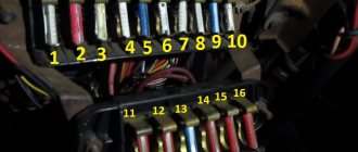
If after replacing the light bulb the low beam headlight on 2106 still does not light, you should check the fuses. They are located under the instrument panel.
Fuse box location
In this case, you need to pay attention to two fuses:
- No. 5 – protects the left headlight from short circuit;
- No. 6 – protects the right headlight.
It must be said that the low beam on the VAZ 2106 often does not work due to the fuse contacts being bent or oxidized. In this case, they need to be bent and cleaned. If the protective element has melted, it must be replaced.
Fuse diagram
Troubleshooting other problems
If the low beam on a VAZ 2106 does not light up, then to detect a malfunction you will need a multimeter to test the wiring, or at least a test light. The circuit and equipment should be checked according to the diagram below.
Headlight switching diagram
It must be said that the high and low beam relays on the VAZ 2106, which are indicated in the diagram as numbers 6 and 4, often fail.
Therefore, you can start checking with them.
Low beam relay for VAZ 2106 (no. 3)
- If there is no voltage supplied to the relays and fuses, you should check the wiring section from switch No. 5 to terminal No. 86 on the relay, as well as the section from the switch to the external lighting switch No. 8. If the machine's wiring is normal, then the switch has failed.
- If voltage is supplied to the fuses, then an open circuit must be looked for in the area from the block to the headlights. Often the breakdown is due to poor ground contact. In this case, you just need to clean the contact.
These, in fact, are all the reasons why external lighting may not work on the “six”.
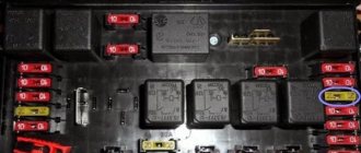
Relay mounting block
The mounting block is located under the hood, near the windshield.
K1 – headlight cleaner relay. If the headlight cleaners do not turn on, check fuses F1 and F7. Inspect the wiper mechanism; dust may have gotten into it or a stone has flown in, damaging or jamming its operation.
K2 – relay-interrupter for direction indicators and hazard warning lights. If your turn signals or hazard lights stop working, check fuses F2 and F16, this is a relay. If the hazard lights work but the turn signals do not, check the power handle, its contacts and connector. If only the emergency lights do not work, check the power button, contacts and wiring. Don't forget to check the turn signal bulbs. There may be a short circuit in one of the headlights. Carefully inspect the connectors and wiring for insulation damage.
If the turn signals work unstably or intermittently, this may be caused by poor contacts in the mounting block, as well as burnout or damage to its tracks. Contact may disappear not only in the block, but also in the headlights themselves, as well as on the way to them. If the wiring has been changed or something has been done to the wires, check them first.
K3 – windshield wiper relay.
If your wipers stop working, first check the relays and contacts. The steering column switch could also stop working or its contacts could oxidize. Inspect the wiper mechanism; due to poor tightening, the nuts securing the mechanism slats may have become loose, or a foreign object may have gotten in, interfering with their normal operation.
The motor could burn out, you can check its performance by applying voltage directly to it from the 12 V battery. Near the motor there is another fuse that protects it from overheating. It is located either on the trapezoid bracket or in the motor itself, depending on its type.
K4 – lamp performance monitoring relay.
K5 – power window relay. If your power window does not go up or down, check fuse F6 and this relay. If the window lifting mechanism is of a cable type, it lowers normally but rises with difficulty, it is necessary to lubricate the cables and glass guides with silicone grease. To do this, you need to remove the door trim and get to the mechanism. The motor may have stopped working, in which case it needs to be replaced.
Sometimes it helps to close the glass by hitting the door to temporarily revive the motor. To disassemble the window lifter mechanism, you need to unscrew the bolts securing the brackets and disconnect the glass itself from the mechanism.
If only one window regulator does not work, the problem may be in the power button and its contacts.
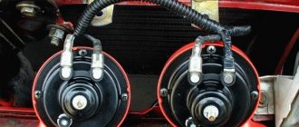
K6 – sound signal relay. If your horn stops working, check fuse F5, relay. The signal may not work due to a lack of contact in the steering wheel. Remove the steering column housing and look at the serviceability of the plates and contacts. Turn the steering wheel left and right; when turning, the mechanism may jam or the contacts may move. One bolt on the casing secures the position of the switch mounting bracket, the second secures the casing.
For the signal to work, you need to securely fix them, setting them in such a way that the contacts close when the switch is pressed. The contacts are located above the steering shaft. The design of the contacts in the steering wheel could also be damaged. Inspect the mechanism; the 3 screws and springs should reliably open and close the circuit.
K7 – rear window heating relay.
If the rear window fogs up and the heating stops working, check fuses F4 and F7, relays, contacts of the heating elements on the glass that may have been burnt or oxidized, as well as the switch button. The heating uses a high current; it would be a good idea to check the tracks on the mounting block board near the specified fuses and relays. The wire going from the switch to the rear window could have frayed and become one of the reasons.
K8 – high beam relay. If only one high beam headlight stops working, check one of the fuses F14 or F15 and the bulb in the problem headlight. Inspect the headlight connector and its contacts. It’s better to call them, then the problem will be easier to find. Check the steering column high beam switch and its contacts. When moving towards you, the headlights should flash with high beams, when switching away from you, switch the low beam to high beam. If the distant one blinks but does not switch, it is most likely the problem.
K9 – low beam relay.
If the low beam in one of your headlights stops working, check one of the fuses F12 or F13, and the lamp in the problem headlight. Check the headlight and low beam switch buttons if both headlights do not light. Contacts in the headlight sockets can also cause the lack of light.
VAZ 2106 Fan and fan relay
4.4. Fan and fan relay
| GENERAL INFORMATION |
UAZ Patriot and Pickup communities Blog ECU and fuel pump relays do not turn on
Do not work in close proximity to fan blades to avoid injury. The fan may turn on spontaneously!
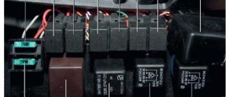
Location of the main engine relay, air conditioning relay and fan relay in the main relay box
| A. A/C relay B. N3 fan relay C. N2 fan relay | D. N1 Fan Relay E. Main Motor Relay F. Fan Circuit Breaker |
Examination
| EXECUTION ORDER |
| 1. If the fan does not turn off when the engine is cool, then disconnect the wiring connector (indicated by the arrow) from the fan thermal switch and unscrew the two nuts securing the thermostat cover to the housing (the upper nut is indicated). Now, when you turn the ignition key to the ON position, the fan should turn on. |
| 2. If the fan does not turn on, check the fan relay, the wiring between the thermal switch and the relay, and the motor itself. |
| 3. The closure of the contacts of the thermal switch (indicated by the arrow) screwed into the thermostat cover is checked with an ohmmeter. Disconnect the wiring connector and connect one of the ohmmeter probes to the pin on the switch, and connect the other probe to the housing. |
| 4. On a cooled engine (fluid temperature below 82° C), the ohmmeter should show a closed circuit. On a warm engine (fluid temperature above 93° C), the ohmmeter should show a gap. |
| 5. To find out the reasons for the electric motor failure (the fan does not rotate on a warm engine, or when the air conditioner is on), check the fuses or fuses (see subsection 12.1). |
| 6. Then disconnect the connector on the fan motor (indicated by the arrow) and connect the motor directly to the battery using wires from the fuse link. If the fan does not rotate, replace the motor. |
| Warning Do not connect the test lead clamps to each other or touch them to any metal part of the vehicle. |
| 7. If the previous test shows that the motor is OK, then the relay, fuse or wiring is faulty. In this case, you should check the fan relay and the main motor relay using the procedure described below. |
Relay test
| EXECUTION ORDER |
| 1. Locate the main mounting block, which is located on the left side of the engine compartment. On vehicles equipped with air conditioning, there is an additional relay box located next to the battery (see Fig. Location of the main engine relay, air conditioning relay and fan relay in the main relay box). |
| 2. Remove fan relay N1 and use an ohmmeter to check the circuits between the terminals, following the illustration. Cars are equipped with Nippondenso or Bosch relays, the pin numbering of which is different. Check the relay in strict accordance with the figure. |
| 3. If the relay turns out to be serviceable, then remove the main engine relay and check it in accordance with the figure. Between pairs of terminals 3–5 and 2–4, the ohmmeter should show a closed circuit. There should not be a closed circuit between pins 1 and 2. If voltage from the battery is applied to terminals 3 and 5, then there should be a closed circuit between terminals 1 and 2, and an open circuit between terminals 2 and 4. |
| 4. If all the tested relays turn out to be in working order, then the car should be submitted for diagnostics to the dealer's car service service or to a specialized workshop. It is not recommended to carry out further testing yourself due to the complexity and variety of circuits used in the vehicle. |
Replacement
| EXECUTION ORDER |
conclusions
Of course, in order to carry out a proper connection or upgrade, you need to know where your car's turn signal relay is located. In most models it is mounted in the fuse box. But some manufacturers put it behind the dashboard, even in the steering column. Therefore, before starting all work, make sure that you know what you are doing, study the electrical and wiring diagrams so as not to make mistakes.
Recently, LED automobile lamps have become used. They are more durable and consume less current. The latter precisely affects the operation of the turn relay, changing its frequency. The frequency of relay operation is tied to the load resistance, that is, to the installed lamps. As the load resistance increases, which is exactly what happens when one of the lamps burns out or opens, the relay begins to operate most often. The same effect is observed when installing LEDs in direction indicators, since their power consumption is less, which means the resistance is much greater.
After studying the material in this article, you will be able to modify the standard turn signal relay for LEDs so that it operates at the frequency you need.
First of all, a little about the standard relay. The 3-pin turn signal relay which will be discussed is installed on cars starting from VAZ 2108 to the present, that is, on VAZ 2109, 2110, 2111, 2112, Lada Priora, Lada Kalina, GAZ cars. Marking 495.3747-ХХ.
To modify the relay, it will be necessary to open the housing. To do this, take a flat-blade screwdriver and remove the housing cover by pulling the plastic latches from two opposite sides.
Now let’s figure out what is responsible for what in this circuit and how we can change the operation so that with increased load the frequency of operation of the direction indicators does not change. The first is connection. Ground is connected to pin 31. 49a - output to lamps, 49 - input “+” from the turn signal switch.
R3 is a current-limiting resistor to the control base of the transistor in the microcircuit; R1 and C11 - these are the radio elements that are responsible for the frequency of the output signal from pin 3 of the microcircuit. From leg 3 power is supplied to the relay winding; Conclusion 7 is also an interesting conclusion. The output controls the change in resistance and, accordingly, voltage at contact 49 a. It is he who gives the command to the microcircuit to change the frequency when the lamps burn out. The microcircuits can be not only those indicated on the diagram, but also, for example, KR1055GP1B, etc. analogues.
Now, presenting the functional purpose of the relay elements, it is not difficult to decide on measures to maintain the frequency of operation of the direction indicators when their internal resistance changes, that is, for example, when installing LEDs.
It is possible to change the capacitance value, double it (replacing it with a 4.7 µF capacitor instead of 2.2 µF - in the photo the capacitance is increased due to parallel connection of an additional capacitor to the standard one), but in this case the alarm system does not work correctly.
It will operate at half the frequency. The option of changing the resistance is also not entirely successful. Since, in fact, here you will have to empirically select a current-limiting resistor at pin 4, which is also not a very good option.
Turning relay switching diagram 495.3747
There remains the last and perhaps the best way out. In fact, remove control over load resistance. By cutting the foil on the printed circuit board (red line) going to pin 7 of the microcircuit, we will get a stable frequency response of the direction indicators.
After this modification, resistor R2 must be reduced to 60 - 200 Ohms.
The only drawback of this modification of the relay for LEDs will be the lack of monitoring of burnt-out LEDs, since we have actually removed the dependence of frequency on load resistance.
Turn signals play an important role in road safety, and their failure can lead to a lot of trouble. A small device - a turn relay - is responsible for the operation of the turn signals. Read about what types of turn relays are used in VAZ cars, how they are designed and work, as well as about their malfunctions and repairs in this article.
Fan relay VAZ 2106 where is the photo Telegraph
Download file – VAZ 2106 fan relay where the photo is located
Ru Mail My World Odnoklassniki Games Dating News Search All projects All projects. Categories All project issues Computers, Internet Topics for adults Auto, Motorcycle Beauty and Health Products and Services Business, Finance Science, Technology, Languages Philosophy, Unknown Cities and Countries Education Photography, Videography Horoscopes, Magic, Fortune telling Society, Politics, Media Legal advice Leisure , Entertainment Travel, Tourism Humor Food, Cooking Work, Career About projects Mail. Ru Auto, Moto Motorsport Auto insurance Choosing a car, motorcycle Traffic police, Training, Traffic licenses, Driving Registration of auto-moto transactions Service, Maintenance, Tuning Other Auto topics. Questions - leaders Mercedes steering rack repair w 1 rate. Tomahawk and Starline car alarms Which alarm system will be better, Tomahawk TW or Starline A91? Category leaders Julia Sh. Anton Vladimirovich Artificial Intelligence. Where is the fan relay located on a VAZ? Premier Master, closed 6 years ago. Ivanych Prosvetleniy 6 years ago Under the hood If you stand at the right front wheel, 15 cm to the right of the washer reservoir Comment deleted Ivanich Prosvetleniy The charging light relay is right at the right wheel to the left of the battery 15 cm And the radiator fan relay, as I wrote, is only at the left front wheel It’s not far from there to the switch on sensor and to the vent Only I take it off for the summer On the pump with a six-blade and that's it Kuzbass Pro 6 years ago I had an A in the mounting block, and put it under the hood for a penny, you'd better buy a book or download it poorly without it, literature is a thing good. Yurich Pro 6 years ago It was a long time ago. In my opinion, there is a body part on the left mudguard, and not the rubber one near the wheel under the hood. There seems to be an expansion tank nearby. In general, remove the wires from the temperature sensor on the radiator, close it so that the relay works and you will hear which switch clicks. It’s a bit collective farm, really, but what did Denis Druzhin remember? Student 6 years ago Catch it, you’ll find everything.. Ru About the company Advertising Vacancies. We are constantly adding new functionality to the main interface of the project. Unfortunately, older browsers are not able to work well with modern software products. For correct operation, use the latest versions of Chrome, Mozilla Firefox, Opera, Internet Explorer 9 browsers or install the Amigo browser.
DIY burning heart for a wedding
procedural map
Samples of comic certificates
Problems in the field of financing in the Russian Federation
How does a mechanical voltage regulator work?
Now let's look at the principle of operation of a mechanical type regulator. When you start the engine, the generator rotor begins to rotate. If the rotation speed does not exceed two thousand revolutions per minute, then the voltage at the generator output is stable. It does not exceed 14.8 Volts. When the engine and generator operate in this way, the regulator does not function and passes current to the excitation winding. But as soon as you increase the crankshaft speed, the relay-regulator comes into operation.
In this case, the winding connected to the brushes instantly responds to excess voltage at the output terminal of the generator set. The winding is magnetized by the core and attracts the armature. This opens the contacts. And if, when operating at low speeds, only one resistor was connected to the circuit, then when the speed is exceeded, all three are used. This reduces the voltage supplied to the excitation winding of the VAZ 2106 generator.
Turn relay VAZ 2106 solved 1 answer
The turn relay on the VAZ 2106 is located in the car interior under the instrument cluster. To get to it and replace the turn signal relay, you must adhere to the following diagram:
• Remove the instrument cluster; use a screwdriver to carefully pry the panel from below at the places where the clamps are attached and pull it out towards you.
• Label the bags with wires and then you can disconnect them. Or use electrical diagrams. Then unscrew the speedometer cable.
• When the tidy is not in the way, you can easily reach the turn signal relay to unscrew the fastening nut. Remove the relay from the stud and 2 ground wires.
Contact regulators
You can still find cars that have mechanical voltage regulators installed. They are extremely imperfect and have a lot of shortcomings, but the owners of such cars are confident that “old is always better.” And every three days they crawl under the hood to adjust the gap and clean the contacts. But using contact systems as an example, it is convenient to consider the principle of operation of regulators as a whole. The essence of the ongoing processes in semiconductor and mechanical ones is somewhat similar.
The design is based on a winding - it magnetizes the metal core. The winding consists of 1300 turns of thin wire. When diagnosing such a relay, you need to know that the resistance of this coil is 17 Ohms. The contacts are made of tungsten. The design includes a shunt and an adjustment plate. There are also several springs and resistors, the latter are switched by mechanical contacts.
Where is the VAZ 2106 cooling fan relay located?
Dear visitors of the site “All about cars”! We will be very grateful for your comments on the video clip “Where is the VAZ 2106 cooling fan relay located?” registration is not required for this. We also ask you to let us know if you have any problems playing the video.
audi a3 2001 1. 6 rodator is cold and the temperature is 95 and one pipe is cold, what is it, help
Hello, I have a Mazda kapel 99g, I recently changed the coolant in the engine, after which the fan began to work very often, while the temperature needle does not rise above the middle at all, what could it be, any thoughts??
I took everything apart and bought a new one, but it turned out to be a relyushka.
very little, for example, my fan did not turn on due to the fact that antifreeze did not flow through the lower expansion tube, the thermostat stuck. At first the fault was with the sensor itself, but then when I crushed the pipe with my hands, antifreeze flowed into it and the sensor started working and started spinning. By the way, even the gasket on the lid was broken
Novel . I watch your videos often. Thank you very much . Everything is intelligible and understandable, and most importantly relevant.
Where have you been before with this video? I drove 340 km on Dolinsk non-carbonated water. The fan did not turn on.
Which fan is better, forced or electric? My fan turns the ramen, that is, it’s forced
I have an injection 2105, tell me where the sensor is located at the bottom of the radiator, it’s not like in the video
The sensors also seem to be sold differently, for example, at 92g. on And one more thing, I’m certainly not a mechanic, but if your thermostat is faulty, the system moves in a small circle: does that mean the sensor won’t work, or am I wrong?
thanks for the info
Hello, if you don't mind, please tell me. When I remove the contacts from the sensor and connect them to each other, the fan does not work. It only works directly from the battery. What could be the reason? the rest of the contacts are new
leave the car and drink beer, respect to the author
Well, I don’t know why the author works at 90. For me it turns on at about 100. Strange, of course. Maybe it's the sensor. I installed a new one.
No one says anywhere why, even though everything is working properly, the fan still doesn’t work
is there a relay here? I had it, but I replaced the relay and it was zero, so tomorrow I’ll try to test the sensor, and what should the relay number be? I had 527. and you?
Paasibo Bro
electronic is better in winter
beautiful about beer respect
well done guy explained everything clearly
GU or generator
The generator in any automotive electrical circuit performs the dominant functions.
The normal functioning and operation of the machine depends on it. Reliable PG is installed in all foreign cars and models of the domestic automobile industry. For example, a GU is placed on the “six”, the charge of which satisfies the need for electricity of any standard component. If you do not overload the generating device of the “six”, then the car is capable of driving many, many more kilometers
However, it is important to carry out preventive procedures in a timely manner - monitor the belt tension and the condition of the brushes
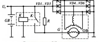
The GU is connected according to the classical scheme. Using the VAZ 2106 generator as an example, let’s consider its functioning. This GU is marked as G-221. It is an AC synchronous electric machine with ELMG excitation. A VB (rectifier) with 6 diodes is built inside the GU.
| 1 | generator rotor winding |
| 2 | generator |
| 3 | generator stator winding |
| 4 | generator rectifier |
| 5 | accumulator battery |
| 6 | ignition switch |
| 7 | battery charge indicator lamp |
| 8 | battery warning light relay |
| 9 | fuse box VAZ -2106 |
| 10 | throttle |
| 11 | temperature compensation resistor |
| 12 | additional resistors |
| 13 | voltage regulator |
A simple and understandable scheme that does not require any subtleties or specific knowledge. On the “six” the PG is located on the engine on the right. It is attached to the tension bar with a nut and to the bracket with its claws.
As you can see, the diagram shows an external regulator. It is marked with the number 13. The generator is indicated with the number 2, the fuse box is indicated with the number 9.
Separately, I would like to consider the relay, which plays an important role in the “six” generator circuit. First of all, it serves to provide information to the driver about the charging status. As is known, it is created by a generating device.
The relay is made on the same principle as all devices that function according to the same properties. The connection is made to terminal 30 of the generator. A separate wire goes through the fuses to the 3Z (lock).
The action of the relay boils down to the following: as soon as the voltage of the BS decreases (falls below the 12-volt value), the relay contacts open, the indicator is activated, giving a sign to the driver.
To better understand the connection diagram, it is recommended that you also familiarize yourself with the principles of battery charging:
- as soon as the key is turned into the 3Z, an electric pulse is supplied to the relay regulator through the fuse (pin 15);
- in the regulator the voltage is transformed and goes further to the positive brush of the GU;
- then, through the brush, the voltage goes to the excitation winding of the GU;
- then - to the negative brush, through which it is brought to ground.
After the relay is activated or after the normal voltage value has been reached in the BS, the GU begins to generate current with the required value. The indicator lamp goes out, and the circuit starts working in factory mode. But when the total voltage drops, the current is not enough, and the contacts open, which leads to the discharge lamp burning.
The constant switching on of the charge indicator lamp indicates that the gene is not working properly. This happens for various reasons. First, you should check the fuses: if they are active, then both relays deserve attention: the regulator and the charger. If they are also in order, then faults must be looked for in the generating device itself.
Before proceeding with replacing the relay, it is recommended to carefully check the functioning of the regulator. The car starts, the speed is kept within the range of 2500-3000 rpm. After this, you need to turn off all current consumers, except the ignition. Then you need to measure the voltage at the battery terminals.
Charging may disappear in the following cases:
- If the generator brushes are worn out.
- In case of malfunction of the generating device.
- If the charging relay is faulty.
- If the rectifier unit (diode bridge) fails.
Thus, installing an external relay-regulator instead of a built-in one will bring a lot of benefits. The fact is that modern charging systems have much more power. Thus, modern memory systems are much more complex than old-style systems.
- Absolutely legal (Article 12.2);
- Hides from photo and video recording;
- Suitable for all cars;
- Works through the cigarette lighter connector;
- Does not cause interference to radios and cell phones.
The VAZ 2106 voltage regulator relay ensures the normal functioning of important vehicle mechanisms and devices. In particular, the adequate operation of the car’s ignition system and its generator, as well as the condition of the battery, depend on it.