All cars have a device for producing sound signals (horn), but its sound does not always suit the owner. This is the main reason for replacing the standard horn with alternative options (for example, with a sound signal from the Volga). Let's look at this improvement in detail.
Nowadays, horns are usually used in pairs. One with a high tone, the other with a low tone. This provides strength and beauty of sound.
Will need to buy:
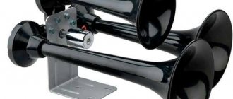
- A couple of sound signals from GAZ 3110 (article number for high tone - 22.3721, for low tone - 221.3721), or an analogue, approximate price 500 rubles; Other sounds in this category.
- 4-pin relay 75.3777-10;
- Relay socket;
- Mounted fuse 10-15A;
- Single-core wire;
- Corrugation for wires;
- Terminals;
- Brackets/brackets for mounting sound signals (optional).
Installation and connection of a sound signal from the Volga is shown using the example of the Lada Vesta sedan. On other cars (for example, Lada Largus, Granta, Kalina, Priora, Niva 2121 or XRAY) all actions are performed in a similar way.
Repair of sound signals on VAZ cars of various modifications
Sound signals, as such, are not among the most complex elements of a car, however, traffic safety and the ability to avoid emergency situations largely depend on their good condition.
Be that as it may, even with all its simplicity of design, the sound signal (including on various modifications of the VAZ) may stop working and if such an unpleasant situation arises, you can most often cope with the problem on your own, it is enough to have the appropriate diagram at hand and follow a few simple recommendations. In general, the connection diagrams for the sound signal on the VAZ “classic” series and on subsequent front-wheel drive models are quite similar and the main differences relate to the relay markings, as well as the location of the fuse. Among other things, on the earliest versions of the VAZ (2101, 2102, 2103 and a number of modifications 2106), the electrical circuit of the sound signal or the presence of a unloading relay is not provided at all.
VAZ sound signal circuit without relay
- Accumulator battery;
- Fuse (one for two signals), located in the fuse block;
- Horn switch in the form of a button on the steering wheel;
- Generator.
VAZ sound signal circuit (2104 – 2107, and also 2121) with relay
- Accumulator battery;
- DC generator;
- A fuse common to the two signals (located in the fuse block);
- Control relay (usually RS-528).
Sound signal diagram for VAZ Samara (2108, 2109, 21099), as well as for VAZ 2113 - VAZ 2115
Sound signal circuit for VAZ 2110 - VAZ 2112, as well as all existing modifications
1.Universal sound horn;
2. Signal control key located on the steering wheel;
3. Fuse in the mounting block (again, there is no relay).
Wiring diagram for the sound signal on the VAZ Kalina and VAZ Priora
- Mounting block with fuse and relay (in the documentation it is sometimes called a control and comfort unit);
- Sound signal control key;
- Universal sound signal.
Possible causes of audio signal failure and methods of elimination
The most common reason for the loss of a sound signal lies in the imperfection of its design and poor protection from moisture and dirt. In other words, during operation, oxidation of the contacts occurs, as well as blocking of the sound membrane (as a result of which there are no vibrations and the necessary sound effect). Such failures can often be eliminated by adding a small amount of WD-40 or its equivalent to the signal, but in order to achieve a guaranteed and long-lasting result, it is still recommended to disassemble the signal and the control key in order to perform more thorough cleaning.
Among other things, on cars equipped with two signals (as a rule, they are of different tones), when one of the elements fails, a significant weakening of the output sound power occurs, and here you will have to determine the failed signal and change it. By the way, many signals are equipped with special adjustment controls, and if wheezing, grinding and other extraneous sounds occur, you can improve the sound quality by rotating the adjusting screw. You can also try to rip off the “soured” membrane by rotating it.
Troubleshooting Electrical Circuits
when there is no signal at all:
— We check the presence and condition of the “ground”, as well as the supply voltage directly on the signal (it is necessary to take into account that on early VAZ models the “plus” “hangs” constantly, and control is carried out by closing the “minus”). If there is a stable plus and a minus appears when the key is closed, the signal itself is faulty and should be changed.
— We check the supply voltage in the sections of the circuit with the fuse, the power relay and the mounting block as a whole;
— We evaluate the condition of the contacts and the overall “mass” of the control button and eliminate all traces of oxidation.
The signal periodically disappears, and extraneous sounds can be heard when sounding:
— We carry out debugging using the adjusting screw.
When turning the steering wheel, the signal begins to sound spontaneously:
— Most likely, the steering column switch is installed incorrectly (too close to the steering wheel);
— Alternatively, there is a short circuit to the ground on the steering column (via the signal control circuit).
Related chapters from other books
External glass and porcelain insulation of electrical equipment and external switchgear
External glass and porcelain insulation of electrical equipment and external switchgear Questions. How to select the specific effective creep distance of external porcelain insulation, as well as flexible and rigid external exposed conductor insulators? You need to choose according to
Location and installation of electrical equipment
Location and installation of electrical equipment Question. What electrical equipment and devices can be installed in EMF? Answer. Can be installed: electric machines; electrical machine converters; start and ballast for
Placement of electrical equipment
Placement of electrical equipment Question. What are the conditions for placing electrical equipment of controlled drives? Answer. Must meet the general requirements set out in chapters 4.3, 5.1, 5.3 of these Rules, as well as technical specifications for
Classification and marking of explosion-proof electrical equipment according to GOST 12.2.020-76
Classification and marking of explosion-proof electrical equipment according to GOST 12.2.020-76. Question. What are the explosion protection levels for electrical equipment? The following levels have been established: explosion-proof electrical equipment of high reliability. Explosion-proof
Electrical faults
Electrical Problems The battery needs attention. The battery is slowly draining. The starter cranks the engine at a low rate of leakage current through the damaged insulation of any wire or device. Hence,
4.3.1. General overview of motivational processes in quality management
4.3.1. Review of motivational processes in quality management. The concept of "motive" is often used to refer to psychological phenomena such as desire, desire, goal, fear, etc., which are reflected in a person in the form of readiness for action, which leads to
Military equipment and equipment on the UAZ-469 vehicle
Military options and equipment on the UAZ-469 With the start of mass production, the UAZ-469 immediately became the main light multi-purpose vehicle of the Soviet Army and the armed forces of all fraternal and allied countries. In the 1970s it was exported to 70 countries. These cars were
General information about the car
General information about the car Basic technical data are presented below, and methods for troubleshooting the latest modernized model of the Volga GAZ-3110 car with a sedan body and a ZMZ-402 engine are presented in the form of logical diagrams.
General procedure for providing assistance
Procedure for providing general assistance Every year, a huge number of people die in car accidents and lost work time. Because of this, 350. 400 million man-days. According to Japanese scientists, if a person is in a state of clinical death
General diagram of electrical equipment
General diagram of electrical equipment Electrical equipment of automobiles is a complex system of interconnected electrical appliances, ignition, fuses, instruments, and connecting wires. Figs
13.2.3. General overview of the state of nanoparticle production
13.2.3. General overview of the state of nanoparticle production Commercial use of any method must be economically feasible. In the laboratory, scientists have developed many interesting and beautiful methods for synthesizing nanopowders, but there are many
Phosphates and total phosphorus
Phosphates and total phosphorus content Phosphorus is an essential element for life, but its excess leads to accelerated eutrophication of water bodies. Large amounts of phosphorus can enter water bodies as a result of natural and man-made processes. Surface erosion
5.4.4. VOLTAGE AND PRECISION SOURCES FOR ELECTRICAL TESTING
5.4.4. Water SOURCES AND STRUCTURES FOR TESTING ELECTRICAL EQUIPMENT Insulation of electrical equipment during operation is exposed not only to operating voltage, but also to power frequency overvoltages, as well as overvoltages resulting from
7.4. Hydraulic DRIVE AND ELECTRICAL ENGINEERING OF CONSTRUCTION MACHINERY
7.4. Entertainment of HYDRAULIC DRIVE AND ELECTRICAL ENGINEERING OF CONSTRUCTION MACHINERY Hydraulic drives of modern construction machines can be divided into several groups according to the nature of failures and methods for eliminating them: pipelines and pipes.,
Installation of relays and Volgov sound signals on Oka
How to independently repair the sound signal on a VAZ-2110.
Well-known from school chemistry lessons, electrolysis is very productively used in our cars, including OK. Unfortunately, not for the benefit of the car owner, but for the benefit of the car manufacturer, who once again saved money on us. We are talking about a sound signal and a relay (or rather, its absence).
Let me remind you that electrolysis is a redox process that occurs on the electrodes when a direct electric current passes through a solution or melt of electrolytes.
The connection diagram for the sound signal in OK is such that + is constantly applied to the signal, and the circuit is closed by - using the signal button on the steering wheel. We add not the most favorable operating conditions for the car, namely moisture and dirt, and we get everything we need for electrolysis, read - rotting of wires and contacts.
Connecting an audio signal through a relay solves two problems at once - connecting an audio signal according to a competent circuit and the ability to connect a Volgovian audio signal (since it is transmitted through the body and cannot be closed by a button on the steering wheel; you can, of course, play around with dielectric fasteners signal, but the method below is much simpler and more effective).
To implement a competent scheme for connecting and installing Volgov signals, we will need:
Wire (length depends on where the signal is installed, in my case about 1.5 m was enough);
Terminals mother - 4 pcs.;
Male terminal - 1 piece and leech or solder in place;
A set of Volgov signals for high and low tones (as of 05.2005 - 320 rubles).
The 1 set of wires shown in the photo can be made in a quiet home environment by first measuring the length of the required wire. With soldering it will take about 10-15 minutes depending on your qualifications. The 1 mounting kit shown in the photo is enough to install two Volga signals without additional soldering and crimping on site, which will take about 10 minutes. It is more convenient to carry out the work with the radiator grille removed (6 screws).
Standard audio signal connection diagram
Upgraded audio signal connection diagram
Sequence of actions for installing sound signals:
Remove - from the battery;
We remove the original sound signal;
We install the relay in its place, having first slightly enlarged its ear with a drill or round file (photo 2);
On the positive wire that went to the sound signal (in my case it was red, you can check it with a test light by throwing the second contact of the light bulb onto the body), at a distance of about 10 -15 cm from the terminal, install a leech and connect the mother-father wire into it (see . photo 1). Second option: instead of installing a leech, we strip the positive wire and wrap a wire about 10 - 15 cm long with a mother terminal on the other end to it. It is advisable to solder this connection.
Next, we connect the positive wire with the extension to the 30th and 86th contacts of the relay in any order;
We connect the remaining wire that went to the signal to the 85th contact of the relay;
To the remaining 87th contact of the relay we connect a double wire (see photo 1), the ends of which go to sound signals;
We put it on the battery.
The signals themselves are placed as desired. In my case, the signals were installed on the spare tire mount (photo 3), due to the fact that it was not used for its intended purpose.
The difference between the headlight switch relay on the Volga
The circuit uses universal electromagnetic relays separately for low and high beams, except for the Gas 3110 car, in the circuit of which a specially designed relay is used that switches the headlights. An electromagnetic relay consists of one or two
fixed contacts, a moving contact fixed to the armature of an electromagnetic coil and an electromagnet. When voltage is applied to the terminals of the coil, an electromagnetic field is created in it, magnetizing the core to which the armature is attracted, closing the contacts.
The Gas 3110 headlight switch relay, like a universal relay, has an electromagnet, but not only a moving contact is attached to its armature, but also a switching device lever. When switching the headlights, power is briefly supplied to the relay, the armature of the electromagnetic relay is attracted, closing the additional high beam contacts and activating the switching mechanism. After releasing the headlight switch lever, the circuit on the relay electromagnet coil breaks; the armature moves away, opening the additional contacts, and the switching device closes the contacts of the low or high beam headlights.
Installation of wires inside the car
Does the sound signal on the VAZ 2110 not work?
Power can be taken directly from the battery terminal, through a fuse. Or find the switching point in the standard fuse box (a diagram of your car is required).
Important! This box from aliexpress has input fuses for each line. All additional wiring is carried out in corrugation, secured to the body with ties
All additional wiring is done in corrugation and secured to the body with ties.
The harness is inserted into the passenger compartment through standard holes in the engine shield.
Inside the cabin, the cable is also laid in corrugation and attached to the structural elements.
All connections are made by soldering, insulated with thermocable and again corrugated.
For quick connection, you can use quick-release connectors (from the same aliexpress).
How to adjust Volgov signals
Cars can be equipped with sound signals of types S-304 and S-305 (collapsible) or 20.3721-01 and 201.3721-01 (non-dismountable).
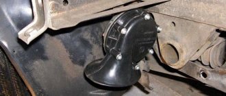
The sound signal is located in the engine compartment and is attached to a bracket welded to the radiator frame panel. The circuit for switching on the sound signal is shown in Fig. 9.20.
Rice. 9.20. Scheme for switching on the sound signal: 1–sound signal; 2–mounting block; 3–horn switch; K6 – audio signal activation relay; A – to power supplies
You will need: a 13" wrench, a screwdriver.
1. Disconnect the wire from the negative terminal of the battery.
Replacing the standard sound signal in case of breakdown
How to connect a signal to a VAZ 2114
First you need to prepare the car for work by putting the parking brake on and turning off the ignition. Then you need to lift the hood and, armed with a “10” key, disconnect the negative terminal from the battery. Then you should dismantle the front bumper, which is best done with an assistant, so as not to damage the paintwork on the bumper itself and on the wings of Vesta.
The figure shows the mounting location of the Vesta signal, its plug and the signal itself.
Once this is completed, all that remains is to disconnect the plug with the wires from the signal horn. Then you can dismantle the signal itself, the bracket of which is attached to the body with one nut. For dismantling you will need an extension, a wrench and a 13mm socket.
Removing and installing the front bumper requires an assistant.
Assembly is carried out in the reverse order - you need to secure the signal, inspect its operation, install the bumper with an assistant and tighten the terminal on the Vesta battery.
Signal installation procedure
Always, when working with a car’s electronic systems, you must first turn off the power. To do this, remove the terminal connected to the car body from the battery.
To get access to the location of the signal on the VAZ-2109 without any problems, you need to remove the radiator mesh. We unscrew the factory signal together with the mesh mounting rail. We also remove the ground wire coming from the signal.
Before starting work, it is worth preparing mounts for the latest signals . You can purchase the iron corner needed for these purposes at any hardware store. The placement of the signal from Volga will be the same as that of the “native” signal. Apply marks to the corner in the same way as you will install it. Next, saw off along the intended strip and drill holes for mounting the new signals. To extend the life of the iron angle, it is worth covering it with paint or any other protective coating. Then take the new signals and record them on the prepared corner. The bolt included in the kit has two purposes: as a fixing element and as a “mass”. So that it can perform the “ground” function, it is necessary to ensure its direct connection with the iron corner. A crown washer works well for these purposes.
How to connect the Volga signal
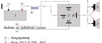
Standard sound signals of LADA cars consume no more than 5A, and Volga horns consume 7A each. In this regard, to connect them it is necessary to use a 4-pin relay. The Volga signal connection diagram is universal for all cars:
Before starting work, it is recommended to disconnect the negative terminal from the battery. All wires are laid in corrugation. We place the relay in a place protected from moisture and dirt. The whole process is also shown in the video:
About the guarantee. If you independently modify the car in terms of electrical components, there is a possibility of refusing warranty service for the car. Therefore, the installation of signals from Volga should be carried out at a service center, where after connection they will be ready to provide a document confirming the quality of work. You can also contact an authorized dealer for such modifications.
Are you satisfied with the operation of the standard sound signal on the LADA model? Are you ready to install a Volga horn? Let us remind you that we previously looked at other methods that can make operating a car more comfortable. For example, installing a gas tank cap bracket or how to make a flip-flop ignition key.
Keywords: lada xray safety | safety of Lada Vesta | safety of Lada Largus | safety of Lada Granta | safety of Lada Kalina | safety of Lada Priora | 4x4 safety | Niva safety | universal article
5
Found an error? Select it and press Ctrl+Enter..
Russian Post will receive more than 1000 Lada Largus cars
The easiest installation of a heated steering wheel for Lada Vesta and Lada XRAY
TO-3 Lada Vesta or why scheduled maintenance is expensive
Checking the efficiency of the cooled glove box Lada Vesta and XRAY
Documentation Volga GAZ-24, 2410, 3110, 3105, 3102
Volga GAZ-31105
GAZ-31105 Volga. Repair, operation and maintenance manual.
GAZ-31105 Volga with a 2.3i engine. Design, maintenance, diagnostics, repair. Catalog of body parts GAZ-3110, GAZ-311105 (PDF, 32 MB)
Volga GAZ-3110/310221
GAZ-3110/310221 Volga with 2.3i 2.5 engines. Device, maintenance, diagnostics, repair.
GAZ-3110 Volga. Express repair manual. GAZ-3110 Volga. Maintenance and repair manual.
Volga GAZ-31029
GAZ-31029 Volga. Repair and maintenance manual.
Volga GAZ-3102
Car GAZ-3102 VOLGA First edition. (PDF)
Manual for repair, operation and maintenance of the Volga GAZ-3102 car. Third edition. (PDF)Repair, operation and maintenance manual for the Volga GAZ-3102 car. Fourth edition. (PDF)Car Volga GAZ-3102. Manual. Seventh edition. (PDF) GAZ cars. (PDF) Catalog of parts for the Volga car model GAZ-3102. This catalog is intended for cars of the 1st production, equipped with a ZMZ-4022 engine. (PDF, 32 MB) GAZ-3102 Volga cars. Catalog of parts and assembly units. This catalog is intended for cars of the 2nd and subsequent editions, equipped with ZMZ-402, ZMZ-406 engines with a “3110” interior. (DjVu, 17 MB)
Volga GAZ-24-10
GAZ-24-10 Volga. Repair manual.
GAZ-24-10 Volga. Design features, maintenance and routine repairs. GAZ-24-10 Volga and modifications. Operating manual.ZMZ-4062.10/4052.10. Guide to diagnosing the engine control system.GAZ/VAZ. Handbook of engine control systems.GAZ/VAZ/UAZ. Injection systems of cars and their diagnostics using NPP NTS devices. Engine ZMZ-4062.10/4052.10. A manual for diagnosing the engine management system. 2.4-liter Chrysler engine for the GAZ-31105 Volga. Repair manual. Cars of the Valdai family Cummins turbo diesel. Operating manual.GAZ-33096. Operating manual.GAZ-33081 Sadko. Operating manual.GAZ-3308 Sadko. Operating manual.GAZ-66-11 and its modifications. Operating manual.GAZ-52/53A/66. Atlas of structures.
Gazelle/Sable
Sable with 2.3 2.5i engines. Device, maintenance, diagnostics, repair.
Cars of the Sobol family Cummins turbo diesel. Operating manual. Cars of the Sobol family. Operating manual. Gazelle Economy. Operating manual. Gazelle Business. Design, maintenance, diagnostics, repair. Cars of the Gazelle family Business LPG. Operating manual. Cars of the Gazelle family Business Cummins turbo diesel. Operating manual. Cars of the Gazelle diesel family. Manual.
The main fuse box is located in the cabin, above the glove compartment and consists of two parts. To access them you need to slide the protective strip.
Photo - diagram
Description
Left block
| 2 | 15A Right headlight (high beam) |
| 3 | 15A Left headlight (high beam), indicator lamp for turning on the high beam headlights |
| 4 | 10A Right headlight (low beam), electric corrector |
| 5 | 10A Left headlight (low beam) |
| 6 | 10A Electric fan relay (ZMZ-4062 engine), seat heating relay, parking brake warning lamp relay, windshield washer jets |
| 7 | 20A Reserve |
| 8 | 20A Cigarette lighter, horns, horn relay |
| 9 | 15A Rear fog lights |
| 10 | 10A Radio receiver |
| 11 | 5A Engine control system unit |
| 12 | 15A Glove compartment lamp, interior lamp, engine compartment lamp |
| 13 | 10A Windshield wiper, headlight washer relay |
Fuse number 8 at 20A is responsible for the cigarette lighter.
Right block
| 1 | 25A Front fog lights, rear fog lights |
| 2 | 15A Heater, heated rear window, heated rear window relay, additional heater |
| 3 | 15A Reversing lights, instruments, speedometer sensor |
| 4 | 10A Stop lamp, portable lamp socket |
| 5 | 10A Hazard warning lamp |
| 6 | 10A Left headlight (side light), fog light relay, side light warning lamp |
| 7 | 20A Heated rear window, lamps, searchlight |
| 8 | 20A Reserve |
| 9 | 15A Electric fuel pump (engine ZMZ-4062) |
| 10 | 10A Engine control system unit (ZMZ-4062 engine) or EPHH unit (ZMZ-402, ZMZ-4021 engines) |
| 11 | 5A Turn signals, side repeaters, breaker, turn signal warning lamp |
| 12 | 15A Heated seats |
| 13 | 10A Right headlight (side light), headlight cleaner relay, luggage compartment lamp, license plate lamps, instrument lamps, cigarette lighter lamp, medical sign lamp |
Installation of sound signals from Volga
Many owners of VAZ 2109, 2108 are not satisfied with the sound of the standard horn of their car. An excellent replacement for the standard nine signal can be the option discussed here for installing a sound signal from the Volga. Many, including the author, have already completed this not at all complicated installation, and do not regret the time and money spent, especially since this modernization is more than compensated by the awareness of the fact that his car has become a little closer to ideal, and is ready for it immediately show it to everyone!
So, for this installation we will need the following materials:
- signals from the Volga with a “mass” on the body
- relay type 90.3747 with mounting flange
- relay socket
- female terminals wide
- heat-shrinkable tube (HERE)
- stranded wire with a cross section of 2.5 mm. sq.
- blade fuse block
- 20 A fuse
- metal corner
Spare parts for modification
First of all, remove the ground terminal from the battery.
To access the standard signal of the VAZ 2109, remove the radiator grille, unscrew the standard signal along with its fastening bar. The signal ground wire is attached nearby, we dismantle it too.
At home, we will first prepare the mounting of signals from the Volga based on a steel angle purchased at any building materials store. We will attach the signals to the standard place where the original signal is attached. We mark the corner at the installation location, saw it off, and drill holes for attaching signals from the Volga. It is also advisable to paint the corner to protect it from corrosion. Next, we attach the signals to the corner. The signal fastening bolt is also a “ground”, so it is necessary to ensure its electrical contact with the angle, for example, by securing the Volgov signals through a castle washer.
We fasten the corner with the signals to the bolt securing the standard Samara signal through a castle washer to ensure contact of the corner with the ground. It is possible that the bolts securing the Volgov signals on the corner will touch the radiator; in this case, we put washers, thereby moving the corner with the signals away from the radiator. Do not forget about the need to preserve the corner with the car body (“ground”). That's it, the mechanical part is over, let's move on to the electrical part.
Signals from the Volga to the VAZ 2109 are connected according to the following scheme:
Electrical diagram for connecting Volgov signals to Lada Samara
We crimp the ends of the wires with appropriate terminals. We hide all connections in a heat-shrinkable tube.
The relay can be mounted on the back of the radiator frame, next to the headlight.
Additional signal activation relay
We fix the ground wire of the relay (pin 86) under the flange of the relay mounting to the car body through a castle washer to ensure electrical contact, having previously installed a tip with a fastening eye on the wire.
We connect the wire from the fuse (30th contact of the relay) to the positive terminal of the battery.
Powering signals directly from battery
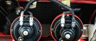
The final result is how signals from the Volga look on the “nine”:
Reinstall the radiator grille:
That's it, the Volga signals are installed, let's buzz and enjoy the noble sound!
You can adjust the sound of signals from the Volga by rotating a special bolt on their body. Also, don’t forget about anti-corrosion protection; you can simply coat all bolted joints with Litol.
PS
Volga signals on the VAZ 2109 and its modifications can be installed without using a relay, by directly connecting to the power wires of the standard signal; the standard signal is already connected through a relay in the fuse block. But this method has disadvantages. The positive power wire of the standard signal is very thin; the signals will not operate at full power due to the voltage drop in this wire, because The Volgov signal is more powerful than the standard one. The power supply circuit for the standard signal is protected by fuse No. 8 in the fuse block, and the cooling fan power supply circuit is also protected by the same fuse. Due to the fact that Volgov signals consume more current (14 A) than the standard one (5 A), this fuse will burn if the fan and Volgov signal operate simultaneously, and the corresponding tracks on the printed circuit board in the fuse block may also be damaged.
Didn't find the information you are looking for? on our forum.
We recommend reading:
What racks to install on a VAZ 2110, the best manufacturers, a brief overview
VAZ 2114 injector cooling fan does not turn off, causes of malfunction
VAZ 2112 16 valves operating temperature
Where is the mass located on the VAZ 2110?
How to connect an alarm system to a VAZ 2107
How to make a Shumka on a VAZ 2114
First gear on VAZ 2107 goes out
VAZ Priora cooling system 16 valves
Replacing the standard signal of a VAZ-2109 with a signal from a Volga
To begin specifically installing the latest signals, the following will be useful to you:
- sound devices from “Volga” with a “mass” installed on the body;
- relay 90.3747 with mounting;
- relay block;
- female type terminals;
- heat-shrink tubing;
- stranded wire, with a cross section of 2.5 mm. sq.;
- fuse block;
- 20 A fuse;
- iron corner.
Video review of installing a signal on a VAZ-2109:
KIA Rio 2011 - electronics
Kia Rio, 2011
Comments 121
Hello, I want to install everything using your method, I have no experience in this, I looked and have questions. 1. Do I need a ground wire if I initially have a U-shaped metal part on which the signals are installed. 2. You don’t show here how you installed a 15A fuse on the power one (I would like to see it or a comment - did you use a remote unit for the fuse in a single number?). I would be very grateful for tips)
1. No wire needed. 2. Yes - separate fuse block (sealed).
Should it be that one horn shouted louder than the other? Or should they shout equally?
Why install an additional relay when the standard one is installed?
I also replaced the regular ones... BB, BB, it's just fire... They're honking, Mom, don't worry...
The wires are musical, they will rot quickly. I installed a powerful one from under the ignition and a powerful relay, the signal is very good
How does the signal work? Is everything normal? The question is just that the relay has enough mass from the standard minus?
Everything works fine - I’m just thinking about changing the low tone - somehow it started to work after a while. So the negative signal goes to the relay only from the standard signal. The minus and plus of the standard one - they only close the relay - there is no load. And the mass goes directly to the signals.
Well, the signals, I understand that they are powered separately) I have a Volgo on my classics)
Fuse diagram for GAZ 3110 and 310221 (1997-2005)
- The starter circuit is designed for short-term high current and does not have a fuse.
- The windshield wiper is protected by an automatic reusable bimetallic fuse.
On the right side of the instrument panel, above the glove compartment, there are two fuse blocks, 13 fuses in each block.
To access the fuses, you need to move the “VOLGA” ornament to the right with your index finger, insert your finger into the recess of the cover and pull it towards you.
| № | A | Function/component |
| Left block | ||
| 1 | 25 | Spare |
| 2 | 15 | High beam right headlight |
| 3 | 15 | Left high beam headlight, high beam headlight warning light |
| 4 | 10 | Low beam right headlight, electric corrector (if installed) |
| 5 | 10 | Low beam left headlight |
| 6 | 10 | Electric fan relay, heated seat relay, parking brake warning relay, windshield washer jets |
| 7 | 20 | Spare |
| 8 | 20 | Cigarette lighter, horn relay, horns |
| 9 | 15 | Rear fog light |
| 10 | 10 | Radio equipment |
| 11 | 5 | Spare |
| 12 | 15 | Engine compartment lamp, glove compartment lamp, interior lamp |
| 13 | 10 | Wiper |
| Right block | ||
| 1 | 25 | Fog lights, rear fog light |
| 2 | 15 | Heater, rear window defroster relay, rear window defroster |
| 3 | 15 | Reversing light, instruments, speedometer sensor |
| 4 | 10 | Brake lights, portable lamp socket |
| 5 | 10 | Alarm |
| 6 | 10 | Left side lights, fog light relay, side light indicator |
| 7 | 20 | Heated rear window |
| 8 | 20 | Spare |
| 9 | 15 | Electric fuel pump (ZMZ-4062-10) |
| 10 | 10 | Engine control system unit (ZMZ-4062), EPHH unit (ZMZ-402) |
| 11 | 5 | Turn signals, repeaters, breaker and turn signal indicators |
| 12 | 15 | Seat heating |
| 13 | 10 | Right side lights, trunk lighting, registration number, instruments, cigarette lighter |
Do-it-yourself signal diagnostics and repair
How to check and repair the horn yourself? For diagnostics, you will need a tester (preferably a digital multimeter, but if you don’t have one, you can use a regular one), crimping pliers, pliers, and a utility knife. Prepare spare wiring and a service manual for the machine.
Checking with repairs is performed as follows:
- The functionality of the fuse and relay is checked; you need to find the mounting block. A more precise diagram is indicated in the technical documentation, but usually the safety device is located in the power supply unit; it can be installed in the dashboard. Once you have located the block, examine the diagram on the back of the block cover to find the fuse. Dismantle the device that is responsible for the operation of the horn and carefully inspect it - if there is an open circuit, this indicates that the fuse is not working.
- But if the device is intact, this does not mean that it is functional. You need to diagnose it using a tester. Set the multimeter to the resistance measurement mode with sound (if we are talking about a digital tester and it has such a function). If you have an analog multimeter, before diagnosing you will need to calibrate the tester; to do this, short-circuit its probes with each other and move the regulator to zero. Then press the tester probes against the contacts of the safety device. If the part is working, then the multimeter will show 0 Ohm, but if not, then if there is no change on the display, we can conclude that the resistance is too high. This indicates a broken fuse and the device needs to be replaced.
- After this, if the fuse is working, you need to find the relay block, which is located either in the engine compartment or in the interior of the car - use the service book to search. Typically the relays are located in the same fuse box. The easiest way to check the operation of the relay is to swap the devices with other similar parts. In most cases, relays are interchangeable, so if after replacing the device the horn starts working, then you can understand that the reason was in the relay.
- You should also check the steering horn switch; a tester is also used for this. If there is no power supplied to it, then of course the button will not be able to respond to pressing.
- Next, diagnose the functionality of the relay switch. To do this, you will need to dismantle the relay and set the resistance measurement mode on the multimeter. One contact from the tester should be brought to the relay switch connector, and the second is connected to the negative terminal of the battery. With this connection, the assistant must press the beep button. As a result, numerical values should appear on the display. If the message Out of Limits appears on the screen, this indicates that the switch is not in working condition, and accordingly, it needs to be changed.
- It would be a good idea to check the horn itself. As a rule, the horn device is located behind the engine radiator grille, directly in front of the main radiator device. Having found the mechanism, you need to determine which of the conclusions is positive and which is negative. Please refer to the technical manual to determine this accurately. Once you know this, connect the horn directly to the car's battery to check its operation. The positive contact is connected to the plus, the negative, respectively, to the minus. When the negative contact is connected, the horn should start working, but if the connection does not produce results, then the device is faulty.
- The next step will be to diagnose the circuit. If you have any suspicions about the health of the electrical circuit, you need to check the grounding of the circuit, as well as the voltage and current values. Determine the mass to accurately identify grounding; for diagnostics, set the tester to measure resistance in Ohms. Connect one contact of the multimeter to the minus of the circuit, and connect the second to ground. As a result, numbers should be shown on the tester screen - if they are present, the wiring is intact. At this stage, you need to check the condition of the contacts. As practice shows, often the cause of failure lies in their oxidation, so it makes sense to clean the contacts.
FakeHeader
That's it, the mechanical part is over, let's move on to the electrical part. As a rule, the horn device is located behind the engine radiator grille, directly in front of the main radiator device. As practice shows, often the cause of failure lies in their oxidation, so it makes sense to clean the contacts. Already crimped wires with terminals are sold in stores.
That's it, the mechanical part is over, let's move on to the electrical part. (easy and fast) Volgov Signals on VAZ 2107
Lada 2106 Zhigulminator › Logbook › Installing a sound signal from GAZ/Volga
There are too many redneck drivers in our city, everyone is messing around somewhere, markings on the road are for beauty, turn signals in cars, in their opinion, only suckers use them. Therefore, to avoid emergency situations, you have to often use the sound signal, but no one is afraid of the standard VAZ signal
, and I actually already had Chinese ones, but they weren’t so hot either. It was decided to install a sound signal from GAZ/Volga S302D - low tone and S303D - high tone
. I bought Russian ones; the market is full of Chinese counterfeits.
I took off the radiator grille, these were the horns
In comparison, Chinese and Volgov
It wasn’t possible to quickly install them right away, the Volga horns are cramped behind the grille, the bolt will hit the radiator when shaking, I didn’t want that. Above the headlights on old bodies there were bolts on both sides for attaching the signal, but mine only had it on the right side near the battery.
So I scratched my head and decided to do it this way.
I bought a KRAB profile connector, it just fits the required dimensions
I bent one part of the cross to attach it to the body; the existing lugs act as additional stops. The negative signal goes through the fastening bolt, so for stability, I connected the negative connector to the CRAB in this way, and trimmed one of the ears to fit the dimensions of the standard connector.
I put a cambric on one of the ears and bent it against the headlight housing to further reduce the possibility of vibrations.
This is what the installed structure looks like, everything is solid, the most important thing during installation is to take into account the lowering hood brackets.
In the standard wiring, the plus comes from the fuse block, and the minus through the button on the steering wheel, so I decided to unload it and put the relay in the gap.
When I bought the relay, I overlooked it and took it without an eyelet for fastening, so I had to attach the relay to the braid with a clamp. Later you can replace it with a relay with an eye and screw it next to the others.
When I removed the grille, I noticed that both halves differed in the thickness of the cells, apparently one was broken and my grandfather replaced one, and there were cracks along the edges. When I bought the relay, I freaked out and bought a new grille and glasses, I replaced it right away, the quality of course is not great.
I am very pleased with the modification, everything has been tested, now if necessary I can easily identify myself in traffic, after which many drivers behave more moderately.
Thank you for stopping by, I will be glad if someone finds it useful or just interesting. I wish everyone less inappropriate behavior on the roads!
Differences from the previous model
The design bureau took into account the wishes of customers and tried to completely solve the problems that were typical for modification 3102.
As a result, the car acquired a number of new functions:
- Non-contact ignition was used, which is why the electrical wiring on the GAZ 3110 changed significantly, the changes especially affected the engine compartment. In addition, contacts on electrical appliances were used and improved, since more powerful impulses into the systems caused burnout of old-style components.
All sources of energy consumption in the Volga, in comparison with the 21st model, the system has changed greatly
- The heated rear window could now operate in two modes, which made it possible to provide good visibility in various external conditions.
- The problem of freezing windshield washer nozzles was solved by adding heating to the design; now the system worked even at very low temperatures.
- A headlight range control was also installed, which was controlled by an electric drive.
- In addition, a number of improvements were made to improve the driving and performance characteristics of the model.
Advice! If you need to thoroughly understand all the nuances, it is best to study the instruction manual from the manufacturer; it describes almost all the important points that you should know about.
This book should be in every car of the brand in question.
Installing a relay in the engine compartment
Unlike the first method, here all the work on installing signals and wiring will be under the hood. The same material will be used, you just need to buy:
- Hanging fuse (like from a mafon-16A) - 25r
- Terminals mother-8pcs-10rub
- Plastic corrugation 2 meters - 8 rubles
We place the horns from the Volga in any convenient place (as in the first option), and connect the wiring according to any of the diagrams: In the first scheme, we take “Plus” for the signal from the fuse block, through its fuse, and in the second scheme we take “Plus” immediately with battery, through a separate 20A fuse. It is best to use the second circuit to connect horns from the Volga to a VAZ 2110.
It is better to place the relay where there is the least chance of moisture getting in. Before doing this, it is good to insulate the relay or wrap it in a bag.
The installation procedure is approximately this:
- Using the “8” key, unscrew the 2 bolts securing the radiator grille and unsnap the 2 lower latches, remove the grille!
- Removing the standard sound signal
- Assembling the wiring according to the diagram
- We isolate all connections, and put the wire that connects the signals to each other into a corrugation (so as not to rub against the radiator)
- We attach the relay in a suitable place
- Putting back the radiator grill
Setting signals without relays
There is another method for connecting signals from the Volga . Since the factory signals are connected via a relay located in the fuse block, your only option is to connect the new signals directly through the “old” wiring. This method is rarely used due to its shortcomings. The fact is that the positive wire used in standard wiring is very narrow and at the physical level will not be able to pass the required voltage, as a result of which the signals from the Volga will not work at full strength.
Industry standard power circuit protection is provided by fuse #8. It is also responsible for protecting the wiring leading to the cooling fan. Due to the fact that the newest signals are stronger than VAZ ones (14 A versus 5 A), the fuse will not withstand the combined operation of the signal and the fan and will simply burn out, which may lead to malfunctions in the fuse box.
Video review of installing signals from Volga on a VAZ-2109:
Source: auto-cool.com
Setting a more powerful sound signal through a Yamaha YBR 125 relay
Guest
I decided to change the sound signal to a more powerful one.
There are two types of sound signals: noise hornless and tonal horn. Hornless signals are considered to be shriller and more difficult to hear, and are recommended for use on highways and in noisy environments. Horn (snail) ones are more suitable for urban conditions. Horn signals are usually installed in pairs (high and low tones). For myself, I settled on the hornless option (loud and shrill).
At an auto parts store I bought a horn from a new VAZ, large and with two terminals ((+) and (-), the old ones come with “snails” with one contact (+) and grounding to ground). The cost of this device was 120 rubles. Since the original signal was designed for a current of only 1.5A, and the new one was 5A, I decided to connect it via a relay so as not to damage the standard button. I bought a simple 4-pin 30A relay (60 rubles) from the same auto parts store. You will also need approximately 1.5 meters of wire and 4 terminals (“female”, with insulation).
An approximate connection diagram is in the attached file (copied from www.niva.faq.msk.ru). The contact labels on the relay correspond to the figure.
In relation to YBR: Remove the wires from the standard horn. The pink one goes to the signal button (-), the brown one goes to the battery (+). In the standard circuit, the signal is constantly powered (even when the ignition is turned off), which is not a buzz at all in our humid climatic conditions.
Connect the pink wire to the contact 85
relay, brown on contact86
.
Now, when you press the signal button, a click is heard - the relay closes contacts 30
and
87
.
We strip the brown wire and attach a short wire to it. We connect it to the contact 30
. Now (+) is constantly applied to the contacts 86
and
30
.
We take 2 long wires. We connect one to pin 87
, the second to the nearest (-). In this case, I simply stripped the pink wire and connected the second wire to it. We put these wires on the contacts of the horn. Everything is ready, you can scare the neighbors /images/smilies/wink.gif
Now about the placement. I screwed the relay in place of the standard signal (it has an eyelet, just under the standard nut). The sound signal itself was attached to the left under the decorative air intake (where it is installed on the European version), under a standard mount. I used the brackets that came with the kit (I just bent them 90 degrees at the top).
The difference between an injector and a carburetor
For a long time, only carburetor-type models were produced. Over time, injection ones appeared. Thanks to this, it was possible to achieve certain characteristics, for example, to reduce the amount of fuel consumed. If you follow the theory about internal combustion engines, then the Gazelle 406 carburetor engine begins to work more powerfully with a corresponding increase in the level of rotation of the crankshaft. How can this be achieved? The mechanism is made in such a way that when you press the pedal sharply, the amount of gasoline vapor increases. This, in turn, contributes to an increase in crankshaft speed.
The 406 injection engine (GAZ often used it) operates using a microprocessor. Thanks to it, even with light pressure on the pedal, the driving dynamics of the car will be improved.