01 December 2016 Lada.Online 89 724 7
All cars have a device for producing sound signals (horn), but its sound does not always suit the owner. This is the main reason for replacing the standard horn with alternative options (for example, with a sound signal from the Volga). Let's look at this improvement in detail.
Nowadays, horns are usually used in pairs. One with a high tone, the other with a low tone. This provides strength and beauty of sound.
Will need to buy:
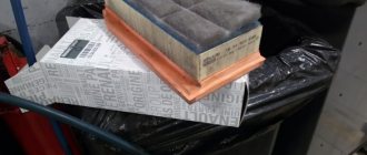
- A couple of sound signals from GAZ 3110 (article number for high tone - 22.3721, for low tone - 221.3721), or an analogue, approximate price 500 rubles; Other sounds in this category.
- 4-pin relay 75.3777-10;
- Relay socket;
- Mounted fuse 10-15A;
- Single-core wire;
- Corrugation for wires;
- Terminals;
- Brackets/brackets for mounting sound signals (optional).
Installation and connection of a sound signal from the Volga is shown using the example of the Lada Vesta sedan. On other cars (for example, Lada Largus, Granta, Kalina, Priora, Niva 2121 or XRAY) all actions are performed in a similar way.
How to install Volga signals on a LADA car
All cars have a device for producing sound signals (horn), but its sound does not always suit the owner.
This is the main reason for replacing the standard horn with alternative options (for example, with a sound signal from the Volga). Let's look at this improvement in detail. Nowadays, horns are usually used in pairs. One with a high tone, the other with a low tone. This provides strength and beauty of sound.
Will need to buy:
- A couple of sound signals from GAZ 3110 (article number for high tone - 22.3721, for low tone - 221.3721), approximate price 500 rubles;
- 4-pin relay 75.3777-10;
- Relay socket;
- Mounted fuse 10-15A;
- Single-core wire;
- Corrugation for wires;
- Terminals;
- Brackets/brackets for mounting sound signals (optional).
Installation and connection of a sound signal from the Volga is shown using the example of the Lada Vesta sedan. On other cars (for example, Lada Largus, Granta, Kalina, Priora, Niva 2121 or XRAY) all actions are performed in a similar way.
How to install a Volga signal
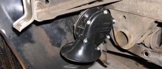
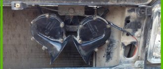
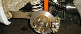
Remove the front bumper (instructions for XRAY, Vesta, Grant, Priora, Kalina, Largus). If it was decided not to remove the standard sound signal (if necessary, you can return to the initial version), then we are looking for a suitable place to install signals from the Volga. Most often they are placed on the front bumper amplifier (on standard mounting bolts), behind the radiator grille or under the headlights on brackets.
How to connect the Volga signal
Standard sound signals of LADA cars consume no more than 5A, and Volga horns consume 7A each. In this regard, to connect them it is necessary to use a 4-pin relay. The Volga signal connection diagram is universal for all cars:
Before starting work, it is recommended to disconnect the negative terminal from the battery. All wires are laid in corrugation. We place the relay in a place protected from moisture and dirt. The whole process is also shown in the video:
About the guarantee. If you independently modify the car in terms of electrical components, there is a possibility of refusing warranty service for the car. Therefore, the installation of signals from Volga should be carried out at a service center, where after connection they will be ready to provide a document confirming the quality of work. You can also contact an authorized dealer for such modifications.
Are you satisfied with the operation of the standard sound signal on the LADA model? Are you ready to install a Volga horn? Let us remind you that we previously looked at other methods that can make operating a car more comfortable. For example, installing a gas tank cap bracket or how to make a flip-flop ignition key.
All mounting points weight VAZ tenth family
| If the electrics in the car start to malfunction, then one of the reasons for this ailment may be poor fastening of the battery mass. Ten have features of mass fastenings depending on the engine and year of manufacture of the car. We check all the attachment points of the negative wire: |
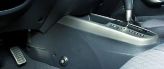
Location of masses in the car interior
| 1 - fuse block.2 - near the driver’s right foot there is a shield, which is attached with a couple of screws, removing it, you will see that everything is like in the picture.3 - in principle, the situation is similar to the point described above, except that the shield is located next to with the left leg of the navigator. |
| The stud in the dashboard behind the mounting block, in order to find it, you need to bend in a certain way. The headlight hydraulic corrector is shown there for reference; the ground pin is located above and to the left of it. Through this mass, the windshield wipers, heater fan (21124) and door lock activators are powered. |
| The console is on the right side, from here it is more convenient to check the very important ground pin, through which the bracket under the ECU is connected to the car body, and accordingly the reliability of the ground of the ECM and the cooling fan depends - this nut also holds the corner that supports the far part of the left panel of the console. |
| ECM harness mass crimps in the console. The connector was removed from the ECU and pulled out onto the driver’s mat, it’s more convenient. I bit the fan ground wire out of the ignition circuit crimp (left in the photo), extended it, put the tip on and connected it separately to the bracket. I soldered all connections for reliability. |
| Weight of the Electric Fuel Pump (EFP) module and fuel level indicator. A black and white wire is attached to the left rear handbrake lever mounting bolt under the floor tunnel. The fuel pump is powered through this mass, and the accuracy of the fuel level reading also depends on it. |
| The ground is on the stud of the fuel pump flange; this wire most likely connects the pump housing to the fuel filter bracket and this was done for safety reasons to equalize the potentials of these two devices. |
Location of masses under the hood of a car
| The thin wire connecting the minus battery and the car body is the main connection for all electricity consumers in the car, and in carburetor modifications also for the engine. Through this connection, all the car's lighting equipment, radio and other devices are powered, depending on the year of manufacture of the car. |
| The connection point for the negative terminal of the battery to the engine block is connected to the upper stud of the thermostat, if you look behind the air filter. The cross-section of the wire was chosen based on the large current consumption of the starter; this wire can easily be traced by hand if it is led from the battery. The starter current flows through this wire, charging the battery, some sensors screwed into the engine block are connected through it |
| Nearby there is another ground connection point to the engine block, it is slightly higher and to the left. The 2112 engine has two brown wires connected to this place - this is the mass of the ECM, that is, the mass of the sensors, ignition module, ECU and cooling fan. The arrow below shows the engine (starter) ground wire from the battery. |
| The mass point under the adsorber - Miha suggested that this is the mass of the right headlight and the mass of the right fog lamp. |
xn--2111-43da1a8c.xn--p1ai
Installation of sound signals from Volga
Many owners of VAZ 2109, 2108 are not satisfied with the sound of the standard horn of their car. An excellent replacement for the standard nine signal can be the option discussed here for installing a sound signal from the Volga. Many, including the author, have already completed this not at all complicated installation, and do not regret the time and money spent, especially since this modernization is more than compensated by the awareness of the fact that his car has become a little closer to ideal, and is ready for it immediately show it to everyone!
So, for this installation we will need the following materials:
- signals from the Volga with a “mass” on the body
- relay type 90.3747 with mounting flange
- relay socket
- female terminals wide
- heat-shrinkable tube (HERE)
- stranded wire with a cross section of 2.5 mm. sq.
- blade fuse block
- 20 A fuse
- metal corner
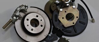
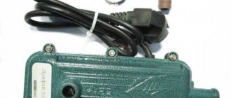
Spare parts for modification
First of all, remove the ground terminal from the battery.
To access the standard signal of the VAZ 2109, remove the radiator grille, unscrew the standard signal along with its fastening bar. The signal ground wire is attached nearby, we dismantle it too.
At home, we will first prepare the mounting of signals from the Volga based on a steel angle purchased at any building materials store. We will attach the signals to the standard place where the original signal is attached. We mark the corner at the installation location, saw it off, and drill holes for attaching signals from the Volga. It is also advisable to paint the corner to protect it from corrosion. Next, we attach the signals to the corner. The signal fastening bolt is also a “ground”, so it is necessary to ensure its electrical contact with the angle, for example, by securing the Volgov signals through a castle washer.
We fasten the corner with the signals to the bolt securing the standard Samara signal through a castle washer to ensure contact of the corner with the ground. It is possible that the bolts securing the Volgov signals on the corner will touch the radiator; in this case, we put washers, thereby moving the corner with the signals away from the radiator. Do not forget about the need to preserve the corner with the car body (“ground”). That's it, the mechanical part is over, let's move on to the electrical part.
Signals from the Volga to the VAZ 2109 are connected according to the following scheme:
Electrical diagram for connecting Volgov signals to Lada Samara
We crimp the ends of the wires with appropriate terminals. We hide all connections in a heat-shrinkable tube.
The relay can be mounted on the back of the radiator frame, next to the headlight.
Additional signal activation relay
We fix the ground wire of the relay (pin 86) under the flange of the relay mounting to the car body through a castle washer to ensure electrical contact, having previously installed a tip with a fastening eye on the wire.
We connect the wire from the fuse (30th contact of the relay) to the positive terminal of the battery.
Powering signals directly from battery
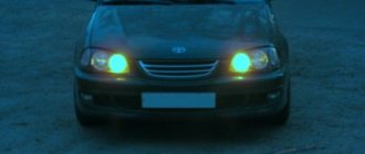
The final result is how signals from the Volga look on the “nine”:
Reinstall the radiator grille:
That's it, the Volga signals are installed, let's buzz and enjoy the noble sound!
You can adjust the sound of signals from the Volga by rotating a special bolt on their body. Also, don’t forget about anti-corrosion protection; you can simply coat all bolted joints with Litol.
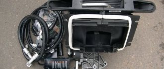
Mounting block Lada Vesta in the car interior
The mounting block is located in a familiar place - near the driver’s left foot. To access the relays and fuses:
- turn the plastic handles (3 pieces) holding the unit cover from below;
- remove the lock on the upper right side of the cover;
- Pull the bottom of the cover, disconnect its upper holders to the instrument panel and remove the unit cover.
Fuse diagram (
- F1 15A K15R Windshield washer mini
- F2 30A *1 /5A *2 K15R Left steering column switch (not luxury/luxury) mini
- F3 10A *1 Left high beam headlight (not luxury) mini
- F4 30A *1 /5A *2 K30S Left steering column switch (not luxury/lux) mini
- F5 15A K15R Heated seats mini
- F6 7.5A *1 K30S Right side lights mini
- F7 10A *1 K30S Left side lights mini
- F8 5A *1 K30S Rear fog lights mini
- F9 3A Direction indicator (turn signals) in the right mini mirror
- F10 5A K15S AMT mini robotic gearbox selector
- F11 10A *1 Left low beam headlight (not luxury) mini
- F12 15A K30S BCM controller (turn signals) mini
- F13 10A K30S BCM controller (own power supply) mini
- F14 10A K30S Mini brake pedal switch off
- F15 5A BTP Power supply for D&O (rain and light sensor), mini headlight range control
- F16 5A BTP Mini brake pedal switch off
- F17 5A BTP Lighting (canopy) for the glove box, trunk, thresholds mini
- F18 3A Direction indicator (turn signals) in the left mini mirror
- F19 10A *1 Right low beam headlight (not luxury) mini
- F20 5A Heated exterior mirrors mini
- F21 15A K15S BU SNPB mini
- F22 5A K15S Gearbox (instrument cluster) mini
- F23 5A K30S Gearbox (instrument cluster) mini
- F24 5A ACC ERA GLONASS, radio mini
- F25 5A VTR Controller ESP9.1 mini
- F26 15A K30S Power supply for mini fuel pump module
- F27 5A K15S Power supply for parking sensors mini
- F28 5A K15S EURU controller (electric power steering) mini
- F29 10A *1 /5A *2 K30S Power supply for mini trailer lighting
- F30 5A K15S Controller ERA GLONASS mini
- F31 5A K30S Controller ERA GLONASS mini
- F32 10A K15S Bus power supply K15M (engine compartment) mini
- F33 5A BTP Window control mini
- F34 5A VTR Power supply for steering angle sensor, mini steering wheel button block
- F35 5A BTP Switch block in the driver's door mini
- F36 15A K30S Radio, mini diagnostic connector
- F37 7.5A K30S Stop lamps right mini
- F38 7.5A K30S Stop lamps left mini
- F39 10A *1 K15R DRL (daytime running lights) not luxury mini
- F40 10A *1 K15R High beam headlight right (not luxury) mini
- F41 20A ACC 12V socket (power supply for additional devices), cigarette lighter JCase
- F42 20A K30S BCM controller (BTP bus power supply) JCase
- F43 20A K30S BCM controller (door locks) JCase
- F44 30A K30S Electric windows (ESP) JCase
- F45 30A K30S Interior heater fan (heater) JCase
- F46 30A *1 K15R Power supply for windshield wipers JCase
- F47 25A *2 K30S EMM controller (PDS, LBS, LGO)
- F48 30A *2 K30S EMM controller (windshield wiper)
- F49 25A *2 K30S EMM controller (PTF, ZPTO, license plate)
- F50 25A *1 K30S EMM controller (LDS, PBS, PGO)
Self-installation of a signal from the Volga on a VAZ
Most models developed by VAZ, including the VAZ 2108, VAZ 2109 and VAZ 21099, which are still widely used today, are equipped with not very euphonious sound signals, which often confuses the owners of these cars. Meanwhile, nowadays there are quite a lot of quite worthy replacements for the standard VAZ signal and, in particular, the option of installing an excellent sound signal from the Volga can be an excellent alternative.
So, to implement such a not too expensive idea, we will need the following equipment and related materials:
- Conventional “Volgov” dual signals with ground output to the housing;
- Relay type 90.3747 together with a block and mounting flange;
- Set of wide terminals;
- 20A fuse together with mounting block;
- Multi-core insulated wire with a cross-section of at least 2.5 mm. sq.;
- Heat-shrinkable tube or electrical tape;
- A piece of aluminum or steel angle.
Practical implementation of the modification
As always, before working with the car’s electrical circuit, you should disconnect the “negative” power wire terminal from the battery, thereby protecting yourself from accidental short circuits.
Next, in order to gain access to the standard signal, it is necessary to completely remove the radiator grille, after which it becomes possible to dismantle the sound device (along with the mounting bar). Don't forget to also disconnect the signal ground wire.
Having assessed the installation location of the standard signal, we modify the mounting of the signals from the Volga using a purchased corner on which we drill holes in accordance with the markings at the installation site. If our corner is made of steel, we cover it with a layer of paint to protect it from corrosion. When attaching signals to the corner, we take into account that one of the mounting bolts will serve as a mass, which means it must be of the appropriate length to ensure reliable contact with the metal part of the car body.
We fasten the corner with the new signals using the bolt securing the standard signal (again, remembering the “ground”, you can use a castle washer). If the fastening bolts on the corner interfere with installation (the bolts touch the radiator), we make adjustments by placing washers.
The connection diagram for Volga signals to a VAZ is as follows:
To make a reliable connection, we crimp the ends of the wires used with terminals, and protect all exposed areas with heat-shrinkable tubing or electrical tape.
As for the relay, there is a place for it on the back of the radiator in close proximity to the headlight unit.
We attach the “negative” wire of the relay (pin 86), equipped with a ring terminal for a screw, to the car body through a castle washer (after having previously stripped the metal at the connection point).
We connect the wire from the 30th contact of the relay (going through the fuse) to the “positive” terminal of the battery, in other words, the main power supply for the signal will be supplied directly from the battery.
The sound of new signals can be adjusted using a special bolt on the housing. In addition, the signal sockets should be positioned in such a way that moisture does not accumulate in them, and it would not hurt to protect all bolted connections with lubricant.
It should be noted that the installation of a Volgov signal on a VAZ can be carried out according to a simplified scheme, that is, without the use of an additional relay. In this case, the connection is made using the standard signal power wires, taking into account the fact that the basic signal uses its own relay located in the fuse block. This method is of course simpler and less expensive, but it has certain disadvantages. The fact is that the positive wire feeding the standard signal is too thin for a more powerful “Volgov” device and the voltage drop across it is too significant (the signal will sound weaker than we would like). In addition, the protective fuse in the standard network protects not only the signal circuits, but also the fan, and its 5A rating is clearly not enough (when both devices operate simultaneously, the fuse quickly burns out and, at the same time, the tracks on the circuit board of the fuse box are often damaged).
Post navigation
How to connect your phone to the radio via usb, aux, bluetooth
We turn on the headlights or low beams, the DRLs go out. Now let's briefly go over the rules for the operation and use of DRLs: DRLs should be used only during daylight hours; It is prohibited to use DRLs in conjunction with side lights, low and high beam headlights, as well as fog lights.
Separately, I would like to dwell on an important point, it concerns the use of DRLs in conjunction with high beam headlights. These are ordinary relays from a set of alarms and other additional equipment
Diagram of a relay containing a diode and connecting its winding: When voltage is applied to the control contacts, the relay is activated and closes or opens the electrical circuit with power contacts. Typical relay circuits. Power contacts are always marked as 30, 87 and 87a. Connecting and installing an LED driver is a waste of time, because the DRLs on LEDs shine regularly for months without any stabilization... However, this statement is easy to dispute. Let's consider connecting fog lights.
With the ignition, in this case, the fog lights cannot be turned on without the engine running, usually the plus from the ignition switch or IGN2 is used, which is best looked for using a voltmeter, since if you use a lamp probe, there is a possibility of damage to the car's electronics. Depending on whether there is voltage on them or not, contacts 87 or 87A close; Contact 30 is the power supply contact of the relay.
That is, if you turn the key in the ignition but do not start the car, the DRLs will light up. One of the contacts, 87a or 87, may be missing.
To watch online, click on the video ⤵
(easy and fast) Volgov Signals on VAZ 2107 Read more
Lada Vesta. Installation of Volgosignals. Very detailed Read more
Volgov signals on Lada Vesta installation Read more
Installation of a signal from the Volga Read more
how to connect a signal through a relay Read more
How to connect a signal through a relay Read more
Signal from Volga to Toyota Crown. More details
HOW TO CONNECT A SOUND SIGNAL THROUGH A 4-PIN RELAY TO A BUTTON Read more
DUSTER install the Volga signal Read more
Volkswagen T3. Installation of Volga signals. More details
CORRECT INSTALLATION OF VOLGO SIGNALS ON A CAR Read more
Automotive relay. How does it work? What is it for? How to connect? More details
VERY LOUD SIGNAL for 1000r/CHEAP flavors/Zhiguli diary Read more
Four-pin relay, connection. More details
Installing a Volgov sound signal on a VAZ Read more
Installation of sound signals from Volga (GAZ) on VAZ 2110, 2112, 2111 Read more
Volgov signals for 2110 installation Read more
#Lada Kalina 2. We install Volgov signals. Where to mount and how to connect? More details
Installation of a signal from the Volga to Granta Liftback Read more
Signal connection diagram via 4-pin relay
In my opinion, everything is already clear, and they have already written about this many times, but it may be useful to someone. For example, I recently gave a car I had made to a man, and over time his signal stopped working. You can’t travel all over Moscow for trifles, so he asked me to draw a diagram for him, I did it, but don’t disappear. I decided to post it publicly.
Description, I will try to use simple understandable language:
Two opposite contacts on the relay, numbered No. 86 and 85, are the so-called control contacts. If voltage is applied to them, the relay will close, and then direct voltage will flow through contacts No. 30-No. 87. Well, let’s say a contact that you need to break and briefly close, let’s say a signal. Why through a relay? Well, let’s take the interior button for example, the contacts on the buttons are weak and are not designed for direct load, and if you apply the plus from the battery through the button, say, to the starter, then after the first use the button will melt. Therefore, through the interior button we connect the control wires to the relay, and the direct plus to the consumer, in our case the signal. Thus, through a relay from the battery to the input (contact No. 87) and output (contact No. 30) to the consumer (Signal).
What is a control minus? Usually, on the relay, the minus goes directly to contact No. 86, and the control plus is opened with a key (button). In our case, the key (button) already exists, this is the signal button on the steering wheel. The way it is designed, the steering shaft is connected to the steering column and body through rolling bearings, and there is always a constant minus on it. Next, the minus from the steering shaft is fed to the core of the steering wheel, a contactor is installed in the steering wheel itself, to which the minus from the steering wheel fits on one side, and on the other side the contact goes to a contact round plate (most often copper or brass) along which on the steering side the stationary contact slides on the shaft, it then removes the minus from the steering wheel button and sends it further to the signal, in our case to the relay, to contact No. 86. So, not everything is so complicated and shrouded in mystery; if you have never dealt with electrics, then don’t go into details, just connect according to the diagram, which in my opinion is quite simple. I hope my article will help someone.
It is often difficult for novice auto electricians and people modifying their car to understand the phrase “connect via a relay.” What does connecting via a relay mean and how to do it? Let's figure it out.
Before studying the wiring diagram for any automotive device via a relay, you need to know what a relay is in general and how it works. This is written about in detail here
. Once you understand the operating principle of this simple device, it will be much easier to figure out how to connect it.
The general meaning of connecting via a relay is the load on the switch that controls the installed equipment. All powerful consumers of electricity in the car (for example, headlights, starter, fuel pump, heated rear window, electric power steering) are connected through a relay. Thanks to this, these devices can be controlled by small, beautiful buttons instead of rough and large switches. In addition, in some cases, the relay allows you to save on wires.
The relay is connected to an open circuit in the electrical circuit. Let's look at installing a relay using the example of a gas pump. Power is supplied to it by the engine control unit (hereinafter referred to as the computer) and in order for the computer board tracks to withstand the current consumed by the pump, they would have to be made too powerful. Passing strong current near sensitive electronic components of a computer can affect their operation. To avoid such problems, a relay is installed between the computer and the fuel pump and the computer is connected not to the pump, but to this little “helper”.
The relay, as it were, divides the wire going from the fuse block to the pump into two parts, which can close inside the relay when voltage is applied to the control contacts of the magnet. As already mentioned in the article about the relay device, the control current is very small and cannot damage the computer in any way. The computer supplies voltage to the control contacts of the relay, and it then “connects” the power circuit within itself and connects the fuel pump.
Using the same principle, the relay is installed on any other electrical consumers in the car. Let's consider connecting fog lights.
The wires to the fog lights come from the fuse box, but they go through a relay along the way. The process of turning the headlights on/off is controlled by a button on the dashboard. When it is pressed, voltage is supplied to one of the control contacts of the relay, and it closes the power circuit - the lamps in the headlights light up. The second control contact of the relay is “mass”, that is, voltage goes through it to the car body, creating an electrical circuit.
Using this circuit, you can connect almost any powerful device and control it with a small, beautiful key. In some cases, a relay can be a salvation from factory defects. For example, in a VAZ-2106, the current flowing to the starter solenoid relay through the ignition switch quickly leads to a malfunction of the lock contact group
. They get rid of this trouble by installing an intermediate relay and changing the power supply of the solenoid relay. After modification, a weak control current begins to pass through the contact group of the lock, and the relay connects powerful power to the starter.
Sound signal GAZ in NIVU
Lately there have been a lot of inappropriate behavior on the roads. Few people pay attention to the native quiet signal. Therefore, I decided to install a signal from GAZ. I bought the following signals produced by LETZ without brackets:
I decided to put it behind the radiator grille, because... Under the hood the sound would still be a little muffled. Standard signal:
To place the signals, I made the following mounts from stainless steel:
Connection diagram via relay:
True, I took the power from fuse No. 15 which is 16A
see also
Comments 121
Hello, I want to install everything using your method, I have no experience in this, I looked and have questions. 1. Do I need a ground wire if I initially have a U-shaped metal part on which the signals are installed. 2. You don’t show here how you installed a 15A fuse on the power one (I would like to see it or a comment - did you use a remote unit for the fuse in a single number?). I would be very grateful for tips)
1. No wire needed. 2. Yes - separate fuse block (sealed).
Should it be that one horn shouted louder than the other? Or should they shout equally?
Why install an additional relay when the standard one is installed?
I also replaced the regular ones... BB, BB, it's just fire... They're honking, Mom, don't worry...
The wires are musical, they will rot quickly. I installed a powerful one from under the ignition and a powerful relay, the signal is very good
How does the signal work? Is everything normal? The question is just that the relay has enough mass from the standard minus?
Everything works fine - I’m just thinking about changing the low tone - somehow it started to work after a while. So the negative signal goes to the relay only from the standard signal. The minus and plus of the standard one - they only close the relay - there is no load. And the mass goes directly to the signals.
Well, the signals, I understand that they are powered separately) I have a Volgo on my classics)
You can try installing Denso horn signals (part number in autodoc JK2720006900). The price is certainly not cheap: 1250 rubles. per pair, but at the same time we get at the output: 1) High-quality imported signals 2) Simple installation of signals, because they have a low amperage and do not require installation via a relay and replacement of a standard fuse 3) A pleasant sound analogue of Volga signals of smaller size and weight. Installation example (www.drive2.ru/l/7132000/)
The difference, for example, between Denco and Volgov signals in terms of amperage consumption is significant! -on Volgov signals, the current consumption is 7A per 1 piece. Each of the “Denco pipes” consumes 4.5 amperes, which, when connected in parallel, gives a total of 9 amperes, which is quite suitable for wiring and the original 10 ampere fuse for many foreign cars. If you have a 10 A fuse, then you MUST turn on the Volga signals VIA A CIRCUIT VIA A RELAY!
I have two Volgovs connected to the standard wiring, I want to convert the standard 10A fuse to an additional relay, what size wire is required?
The larger the cross-section, the better. On Volgov signals, the current consumption is 7A per 1 piece. The process is described here, you can read: www.drive2.ru/l/1554263 www.drive2.ru/l/81822/ It is well described here: www.drive2. ru/l/1850889/ 1mm2 wire cross-section can withstand 10A load. Cross section 0.75 – 7.5A, i.e. a wire with a cross-section of at least 1.5 - 2 mm2 is needed.
I found a table where the following data is given. 1 mm² - 17A 1.5 mm² - 23A 2.5 mm² - 30A
0.5 mm² - 11A 0.75 mm² - 15A
Well, stretch the wires 1.5 mm and don’t bother!
Okay, I'll do that, thanks! (:
Yes, actually, you’re welcome.
I have already changed 2 sets of Volgovskie ones. They're buggy. Made in China.
I have domestic ones - from the moment of installation everything is OK.
Everything on the box is domestic, and on the signals too. And in the box there is a sticker made for such and such an organization.
Mine were without a box, mine were tied with Soviet rope.