Brakes VAZ 2105 Zhiguli
- Repair manuals
- Repair manual for VAZ 2105 (Zhiguli) 1980-1992.
- Brakes
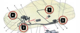
8.0 Brakes Brake system diagram 1 – brake disc;
2 – brake pedal; 3 – vacuum booster; 4 – master cylinder for hydraulic brakes; 5 – pipeline of the front brake drive circuit; 6 – front brake protective cover; 7 – front brake caliper; 8 – vacuum pipeline; 9… 8.1 Possible malfunctions, their causes and methods of elimination CAUSE SOLUTION METHOD Insufficient braking efficiency Leakage of brake fluid from the wheel cylinders of the front or rear brakes Replace unusable parts of the wheel cylinders, wash and dry the pads and drums, bleed the hydraulic drive system Air…
8.2. Checking and adjusting brakes (Category). See the list of materials inside...
8.3 Clutch and brake pedal bracket Details of the clutch and brake pedal bracket 1 – bracket; 2 – nut; 3 – spring washer; 4 – inner bushing of the brake pedal; 5 – outer bushings of the brake pedal; 6 – brake pedal; 7 – spacer sleeve; 8 – brake pedal release spring; 9 – outer bushings ped...
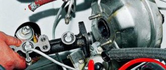
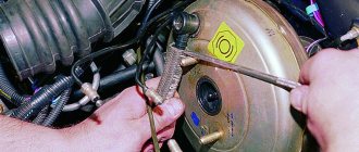
8.4 Vacuum booster The vacuum booster is attached to the plate of the clutch and brake pedal bracket on four studs 6 (see Fig. Vacuum booster) with nuts, and the main cylinder is attached to the vacuum booster on two studs 26. An outer rubber band is clamped between the body 2 and the cover 4 23 apertures, which divides ...
8.5. Master cylinder (Category). See the list of materials inside...
8.6. Front brakes (Category). See the list of materials inside...
8.7. Rear brakes (Category). See the list of materials inside...
8.8. Rear brake pressure regulator (Category). See the list of materials inside...
8.9. Parking brake (Category). See the list of materials inside...
↓ Comments ↓
1. Vehicle operation
1.0 Vehicle operation 1.1. Starting the engine 1.2 Controlling the gearbox 1.3 Driving the vehicle 1.4 Braking and parking 1.5 Operating a new vehicle 1.6 Adjusting the ignition timing 1.7 Precautions when operating the vehicle 1.8 Caring for the body 1.9 Storing the vehicle
2. Car maintenance
2.0 Vehicle maintenance 2.1 Maintenance operations
3. General information
3.0 General data 3.1 Technical characteristics of vehicles 3.2. Controls 3.3. Control of interior ventilation and heating 3.4 Tightening torques for threaded connections 3.5 Tools for repair and maintenance 3.6 Used fuels, lubricants and operating fluids 3.7 Basic data for adjustments and monitoring
4. Engine
4.0 Engine 4.1 Possible malfunctions, their causes and methods of elimination 4.2 Removing and installing the engine 4.3 Disassembling the engine 4.4 Assembling the engine 4.5 Bench tests of the engine 4.6 Checking the engine on the car 4.7. Cylinder block 4.8. Pistons and connecting rods 4.9. Crankshaft and flywheel 4.10. Cylinder head and valve mechanism 4.11. Camshaft and its drive 4.12. Cooling system 4.13. Lubrication system 4.14. Power system 4.15. Carburetor 2105-1107010 4.16. Carburetor 21051-1107010
5. Transmission
5.0 Transmission 5.1. Clutch 5.2. Gearbox 5.3. Cardan transmission 5.4. Rear axle
6. Chassis
6.0 Chassis 6.1. Front suspension 6.2. Rear suspension 6.3. Shock absorbers
7. Steering
7.0 Steering 7.1 Possible malfunctions, their causes and methods of elimination 7.2. Inspection, check and adjustment of the steering 7.3. Steering gear 7.4 Steering gear rods and ball joints 7.5 Bracket for pendulum arm
8. Brakes
8.0 Brakes 8.1 Possible malfunctions, their causes and methods of elimination 8.2. Checking and adjusting the brakes 8.3 Clutch and brake pedal bracket 8.4 Vacuum booster 8.5. Main cylinder 8.6. Front brakes 8.7. Rear brakes 8.8. Rear brake pressure regulator 8.9. Parking brake
9. Electrical equipment
9.0 Electrical equipment 9.1 Possible malfunctions, their causes and methods of elimination 9.2 Circuits protected by fuses 9.3. Battery 9.4. Generator 9.5. Starter 9.6. Ignition system 9.7. Lighting and light signaling 9.8. Sound signals 9.9. Windshield cleaner 9.11. Heater fan electric motor 9.12. Control devices 9.13. Carburetor pneumatic valve control system
10. Body
10.0 Body 10.1 Possible malfunctions, their causes and methods of elimination 10.2. Doors 10.3. Hood, trunk lid, bumpers 10.4. Body glazing, windshield and headlight glass washers 10.5 Instrument panel 10.6. Seats 10.7. Heater 10.8. Body frame repair 10.9. Paint coatings 10.10. Body anti-corrosion protection
11. Car modifications
11.0 Vehicle modifications 11.1. Features of repair of VAZ-21051 and VAZ-21053 cars 11.2. Features of repair of VAZ-2104 and VAZ-21043 cars 11.3 VAZ-21044 cars with a fuel injection system 11.4. Central fuel injection system design
12. Electrical circuits
12.0 Electrical diagrams 12.1 Interactive electrical diagram of the VAZ-2105 car 12.2 Electrical diagram of the VAZ-2104 car 12.3 Electrical connection diagram of the injection system 12.4 Connection diagram of the instrument cluster 12.5 Connection diagram of the brake system warning lamps 12.6 Connection diagram of the headlight cleaners and washers 12.7 Connection diagram of the heater fan motor 12.8 Diagram inclusion windshield cleaner and washer 12.9 Diagram for switching on direction indicators and hazard warning lights
Rear brake system
Rear wheel brake
| 1 – Wheel cylinder; 2 – upper tension spring of the pads; 3 – pad lining; 4 – brake shield; 5 – inner plate; 6 – rear cable sheath; 7 – lower tension spring of the pads; 8 – front brake pad; 9 – pad support plate; 10 – rivets; 11 – oil deflector; | 12 – pad guide plate; 13 – rear parking brake cable; 14 – rear cable spring; 15 – rear cable end; 16 – rear brake pad; 17 – block support post; 18 – lever for manual drive of the pads; 19 – rubber cushions; 20 – pad spacer; 21 – finger of the lever of the manual drive of the pads |
| 1 – block stop; 2 – protective cap; 3 – cylinder body; 4 – piston; 5 – seal; 6 – support cup; | 7 – spring; 8 – crackers; 9 – thrust ring; 10 – thrust screw; 11 – fitting; A – slot on the thrust ring |
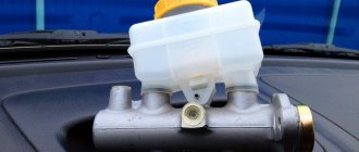
Master cylinder: its purpose and functions
During the braking process, the driver directly acts on the brake pedal, which is transmitted to the pistons of the master cylinder. The pistons, acting on the brake fluid, actuate the working brake cylinders. From these, in turn, pistons extend, pressing the brake pads to the drums or discs. The operation of the brake master cylinder is based on the property of brake fluid not to be compressed under the influence of external forces, but to transmit pressure.
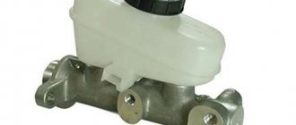
The master cylinder performs the following functions:
- transmission of mechanical force from the brake pedal using brake fluid to the working cylinders;
- ensuring effective braking of the car.
In order to increase the level of safety and ensure maximum system reliability, two-section master cylinders are installed. Each section serves its own hydraulic circuit. In rear-wheel drive cars, the first circuit is responsible for the brakes of the front wheels, the second - the rear. In a front-wheel drive car, the brakes of the right front and left rear wheels are served by the first circuit. The second is responsible for the brakes of the left front and right rear wheels. This scheme is called diagonal and is most widespread.
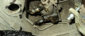
Basic faults
Despite the simplicity of the design and the small number of moving elements, the GTZ often ceases to perform its functions normally due to malfunctions.
It is not difficult to detect a breakdown of the GTZ. The first signals of a malfunction will be given by the brake pedal. Any change in its behavior when pressed (lightness, increase in force, etc.) indicates a breakdown. But it will signal the emergence of problems throughout the system. Checking the system on the highway allows you to more accurately identify the malfunction (the car accelerates, and then emergency braking is performed). And then the traces determine how the system works. Afterwards, all that remains is to visually inspect all the components of the drive for leaks.
The main malfunctions of the master brake cylinder are:
The master cylinder loses its seal, usually due to severe wear or damage to the sealing collars. In this case, liquid can flow between the chambers and also come out of the housing. This allows air to enter the system. As a result, the pressure decreases significantly and the effectiveness of the braking system deteriorates.
Video:Replacing the master brake cylinder VAZ 2108 2109 2110
Air leaks in the system may occur due to blockage of the ventilation hole in the tank lid. Because of this, when the liquid moves, a vacuum is formed in the tank, which is compensated by air penetrating through the cuff. As a result, airing of the system causes a decrease in the efficiency of the system.
Piston jamming can occur for two reasons - debris entering the cylinder through the tank or the formation of rust on the internal surfaces of the housing. This causes one of the circuits to stop working.
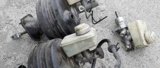
Restoring the performance of the gas turbine engine is possible only in case of wear or damage to the seals or clogging. Special repair kits are sold for repairs.
Often, washing the cylinder and replacing rubber elements allows you to completely restore functionality. But there are also cases when such measures do not help and the problem can only be solved by replacing the assembly.
Source
Principle of operation
Now let's look at how it all works: due to the action of springs, the pistons are set in their original position. In this case, the compensation channels are open, the chambers are completely filled with liquid (the system is connected to the atmosphere).
When the driver presses the brake pedal, the rod connected to it moves. This rod, overcoming the force of the spring, pushes the first piston. As it moves, it closes the compensation channel, which leads to sealing of the circuit (it is disconnected from the atmosphere) and opens the bypass (liquid from the tank enters the cavity behind the piston). At the same time, the pressure in the chamber begins to increase. One part of the liquid from it goes into the pipelines, acting on the brake mechanisms, while the other pushes the second piston. While moving, it does the same thing as the first one - it closes one channel and opens another, and also pushes liquid into the pipelines.
When the pedal is released, the springs return the pistons to their original position. At the same time, the liquid present behind the pistons returns back to the tank through the bypass channel (all this eliminates the occurrence of vacuum). Having returned to the initial position, the pistons open the compensation channels, connecting the system to the atmosphere (the pressure in it is equalized).
Now let's look at how the GTZ works if one of the circuits has lost its tightness. First, let's analyze the situation when the circuit for which the first piston was responsible is damaged. Since it is depressurized and there is no liquid in front of the piston, when you press the pedal, the pressure in the chamber will not increase. The piston, encountering no resistance, will move all the way and will mechanically begin to influence the second piston. And he, in turn, moving, will fulfill his function - ensure the injection of fluid into the mechanisms of his circuit.