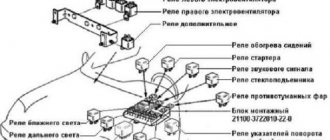
Almost all electrical devices on these cars are designed for 12 volts. In this case, the amperage can vary from hundreds of amperes to tens of milliamps. To separate power and control currents, a switching relay is used. This prevents the wires from getting too hot or catching fire. At the same time, it reduces the overall amount of wiring in the car. Location of switches in the car:
- On the left under the dashboard is block 1 under the first set of fuses. Here are the relays for the Niva 21214 fuel pump, ignition, main switch and both electric fans.
- To the right of the steering column, the relay block is responsible for the fog lights, heated rear window of the trunk door and both types of light (two elements for high and low beam).
- Above the second block are the hazard warning and turn signal relays.
- The starter relay on Niva 21214 is designed for several hundred amperes and is installed in the engine compartment.
It is important to maintain the normal condition of electrical circuits and replace their elements with original ones. Otherwise, complete failure of the controlled unit and a complete stop of the vehicle are possible.
Engine control system fuse box
Scheme
Designation
| 1 | 15A 1* ECM sensors Starter relay Canister purge valve |
| 1 | 7.5A 2* Controller |
| 1 | 3: Electric fuel pump relay (contacts) Electric fuel pump |
| 1 | 30A 4.5* Cooling fan |
| 2 | 15A 1* Injectors Ignition coils ECM controller Right electric fan relay Left electric fan relay |
| 2 | 15A 2* Electric fuel pump relay (contacts) Electric fuel pump |
| 2 | 30A 3* Reserve |
| 2 | 30A 4.5* Cooling fan |
| 3,4 | 30A 1* Electric fans (right, left) Right electric fan relay Left electric fan relay |
| 3 | 15A 2* Main relay |
| 3 | 15A 3* Controller |
| 3 | 15A 4* Ignition coil, power supply for fan relay control, controller, injectors |
| 3 | 15A 5* Ignition relay |
| 4 | 15A 3* Main relay Electric fan relay (winding) Electric fuel pump relay (winding) Vehicle speed sensor Canister solenoid valve Oxygen sensor Mass air flow sensor Controller |
| 4,5 | 30A 2* Electric fan relay (winding) (right, left) Electric fan motor (right, left) |
| 4 | 15A 4* Mass air flow sensor, phase sensor, heating oxygen sensor (two), canister purge valve, DS |
| 4 | 15A 5* Electric fuel pump |
| 5 | 15A 1* Electric fuel pump Electric fuel pump relay |
1* - 2021-2021, 2* - 2021-2021, 3* - 2007-2008, 4* - Cars with Bosch ME17.9.7/M74 controllers, 5* - Cars with 7.9.7 controllers.
Engine Control Relay Box
It is located under the main fuse box and consists of 5 relays and 1 fuse.
Scheme
Electrical diagram of the block
Decoding
- Ignition relay
- Main relay
- Right cooling fan relay
- Left cooling fan relay
- Fuel pump relay
- Fuel pump fuse F5 15A
The only difference between Nivas with injection and carburetor systems is due to the fact that the engine control relay unit can be located under the hood of the car in a specially designated compartment.
Where are the blocks and relays located in Niva 21214 and 21213
The main power supply in these models is located under the lower edge of the instrument panel protection. Additional fuses in Niva 21214 for the injector are located to the left. This block is responsible for controlling fuel injection. There are also relays for monitoring the operation of the wipers and a set responsible for the motion control system.
Another fuse box is installed in the body to the left of the main one. They are responsible for the cooling system and how the engine works. There is also a diagnostic connector. The relay that controls the starter is located either next to the main power supply, or under the hood next to the brake fluid reservoir.
Main fuse box
Scheme
Purpose
| 1 | 16A Heater fan electric motor Relay (winding) for headlight wipers and electric motors for headlight wipers in all wipe positions except the initial Relay (winding) for turning on the rear window heating Electric motors for the rear window cleaner and washer Electric motor for the windshield washer |
| 1* | 16A Lamps Horns Socket Lighter Brake light lamps |
| 2 | 8A Relay and electric motor of the windshield wiper Turn signal lamps and relay-interrupter for direction indicators and hazard warning lights (in turn signal mode) Turn signal indicator lamp Tail lights (reversing light lamps) Generator excitation winding (when starting the engine) Differential lock activation indicator lamp in the transfer case Indicator lamp for turning on the parking brake Indicator lamp for the emergency condition of the service brake system Indicator lamp for insufficient oil pressure Fluid temperature indicator in the engine cooling system Fuel level indicator with a warning lamp for fuel reserve Indicator lamp for battery charge Indicator lamp for closing the carburetor air damper Tachometer Electric heater motor Relay headlight cleaners and washer (with the headlight cleaner and washer switch button not pressed) Headlight wiper electric motors in all brush positions except the initial one* |
| 3 | 8A Left headlight (high beam lamp) Indicator lamp for turning on the high beam headlights |
| 4 | 8A Right headlight (high beam lamp) |
| 5 | 8A Left headlight (low beam) |
| 6 | 8A Right headlight (low beam) |
| 7 | 8A Left front light (side light) Right rear light (side light) License plate lights Indicator lamp for turning on side lights |
| 8 | 8A Right front light (side light) Left rear light (side light) Instrument lighting lamp Heater control lever backlighting lamp Cigarette lighter lighting lamp Illumination lamps for switches and switches |
| 9 | 16A Direction indicators and relay-breaker for direction indicators and hazard warning lights Rear window heating element and relay (contacts) for its activation |
| 9* | 8A Warning lamp and oil pressure gauge Coolant temperature gauge Fuel level gauge with reserve warning lamp Parking brake warning lamp Brake fluid level warning lamp Turn indicators and corresponding warning lamp Carburetor choke control warning lamp Battery charge warning lamp Carburetor shut-off valve Tachometer Rear lights (reverse light) Differential lock warning lamp Turn signal relay interrupter Heated rear window (control circuit) |
| 10 | 16A Sound signal Cartridge for connecting a portable lamp Interior lamps Tail lights (brake lamps) |
| 10* | 8A Voltage regulator Generator excitation winding |
| 11 | 8A Turn signal lamps and relay-breaker for turn signals and hazard warning lights (in hazard warning mode) Rear fog lamp |
| 12 | 8A Daytime running light relay, daytime running light lamps |
| 12* | 8A Headlight cleaner and washer relay (with the headlight cleaner and washer switch button pressed) Headlight washer electric motor Headlight cleaner electric motors at the moment of start-up and when the brushes pass the initial position |
| 13 | 8A Rear lights (fog light lamps) Electric motors for headlight cleaners at the time of start-up and when the brushes pass the initial position Relays (contacts) for headlight cleaners Electric motor for headlight washers |
| 14 | 16A Cigarette lighter |
| 15 | 16A Backup Heated rear window (power circuit) |
| 16* | 8A Hazard warning switch and direction indicators in hazard warning mode Rear window wiper and washer |
Also interesting: Chevrolet Niva |
VAZ 2123 from 2001, front brake instructions online. Fuse number 14 or number 1 at 16A is responsible for the operation of the cigarette lighter, depending on the year of manufacture.
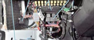
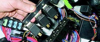
Actual location
Almost all electrical devices on these cars are designed for 12 volts. In this case, the amperage can vary from hundreds of amperes to tens of milliamps. To separate power and control currents, a switching relay is used. This prevents the wires from getting too hot or catching fire. At the same time, it reduces the overall amount of wiring in the car. Location of switches in the car:
- On the left under the dashboard is block 1 under the first set of fuses. Here are the relays for the Niva 21214 fuel pump, ignition, main switch and both electric fans.
- To the right of the steering column, the relay block is responsible for the fog lights, heated rear window of the trunk door and both types of light (two elements for high and low beam).
- Above the second block are the hazard warning and turn signal relays.
- The starter relay on Niva 21214 is designed for several hundred amperes and is installed in the engine compartment.
It is important to maintain the normal condition of electrical circuits and replace their elements with original ones. Otherwise, complete failure of the controlled unit and a complete stop of the vehicle are possible.
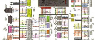
1 – engine control system fuse block; 2 – windshield wiper relay; 3 – fuse blocks; 4 – engine control system relay block.
The fourth relay block is located above the gas pedal.
1 — engine control system fuse box; 2 — windshield wiper relay; 3 — fuse blocks; 4 — relay block of the engine control system.
The fuses in VAZ cars, as well as in the Niva, are located directly inside the car; they are covered by a shield, usually on the dashboard.
This allows, if necessary, to disassemble and carry out repairs using available tools. This approach is especially helpful in cold weather - there is no need to carry out repairs outside, and the cost of self-replacement will be much lower than in a service center.
The above circuit includes components such as relays and fuses. The mounting block includes the following elements presented in the table.
| Element designation | Protected Circuits |
| Relay | |
| K1 | Responsible for the light bulbs inside |
| K2 | Proper operation of windshield wipers and wipers. |
| K3 | Device for designating sensors indicating the direction of turns. |
| K4, K5 | Low and high beam blocks. |
| K6, K7 | Connection of non-fixed assets. |
| K7 | Rear window heating unit. |
| Circuit breakers | |
| F1 | Signal lights, license plate lights, trunk and glove compartment lights, 5A. |
| F2 | Low beam left side lighting, 7.5A. |
| F3 | Left headlights, high beam, 10A. |
| F4 | Fog lighting, left headlights, 10A. |
| F5 | Fuse for power windows, 30A. |
| F6 | For connecting portable lighting, 15A. |
| F7 | The unit responsible for the engine cooling fan, as well as for triggering the sound signal, 20A. |
| F8 | Heated rear windows, 20A. |
| F9 | Recirculation unit, cleaning headlights, windshield; 20A. |
| F10 | Additional, maybe for battery charging. |
| F11 | Side light right, 5A. |
| F12 | Right headlight, low beam, 7.5A. |
| Ф13,14 | Fog lighting, right headlights, 10A. |
| F15 | Fuse for heated seats and closing the luggage compartment, 20A. |
| F16 | Alarm system operation, 10A. |
| F17 | Internal light, serviceability of the on-board computer, 7.5A. |
| F18 | Responsible for the cigarette lighter, light in the glove compartment, 25A. |
| F19 | Serviceability of central locking, brake light, reverse lights, generator windings, 10A. |
| F20 | Rear fog light, 7.5A. |
If any equipment on a car fails, the first thing you need to do is check whether the fuse is intact. This is not difficult to do and even a novice motorist can do it, and there is no point in going to a service station for this. A simple replacement can cost you a pretty penny. To do this, just find the VAZ 2121 Niva fuse box, which the designers placed in a very accessible place.
Electrical fuses on cars are changed if they blow out, without fail observing their rating. But other situations also happen on a VAZ 2121 Niva. For example, many motorists complain that sometimes electrical fuses simply fall out of the block. That is why it is recommended to replace the old unit with a new one, in which the safety elements hold up much better.
Location
The fuses in the VAZ 2121 Niva are located inside the vehicle and are covered with a special casing. This is a convenient enough place to replace a burnt-out one at any time and at the same time you can get by with the most ordinary tools. This is especially important in winter or when it rains; there is no need to go outside if a breakdown occurs on the way.
Table with decoding of the scheme
In order to replace a blown electrical fuse, special knowledge and skills are not required. Everything is very simple.
Additional relay block
This block is located above the gas pedal.
Scheme
Description
- Rear fog lamp relay
- Rear window heating relay
- Low beam relay
- High beam relay
A little higher, above the block, a relay can be installed - a breaker for the turn signals and hazard warning lights.
Separate fuses and relays can be installed under the hood: on cars with ABS, on the left side of the engine compartment near the ABS hydraulic unit, a block with fuses is additionally installed that protect the elements of the anti-lock brake system and the starter relay not far from the starter itself.
Examination
Read
In order to check whether the traction relay , you must first get to the starter. It is located under the hood, in a standard place for VAZs - on the left below the battery, near the gearbox.
The starter itself and the retractor are located in one housing, which also has two terminals. When dismantling or reinstalling the device, you should be extremely careful not to short-circuit these terminals.
You need to check the voltage limit that the traction relay . The limit voltage is no more than 8V. In addition, the temperature during the actuation process should not be higher than 25°C, otherwise you will not get reliable operation and protection of the starter.
In addition, you can sometimes visually notice a breakdown. In this case, it is necessary to install a new mechanism, but first you need to disassemble it.
DIY power supply replacement
Below we will look at the process of replacing the power supply with your own hands. To replace, you will need a new power supply and a socket head set to “8”.
- First, open the hood and disconnect the battery.
- Now, under the instrument panel, find your power supplies. Using an “8” socket wrench, unscrew the two main nuts.
- Having done this, pry up the power supply and remove them from the studs.
- If you are replacing an old component with a new one, you must mark all the wires before doing so. Or take a new power supply unit and insert the wires from the old unit into it one by one. To remove the idle wires, pull them by their plugs.
- To check the functionality of the new power supply, reconnect the battery.
Removal
Dismantling and disassembly is carried out as follows:
- Disconnect the negative voltage from the battery;
- Remove the air filter;
- Disconnect the block of wires going to the traction relay ;
- Unscrew the nut securing the tip of the power drive (wrench 13);
- Unscrew the nuts securing the starter (key 15). The top nut twists easily, but the bottom one still needs to be approached;
- Remove the starter ;
- Unscrew the nut from the lower terminal of the traction relay and disconnect the wires;
- Unscrew its mounting bolts (key 8) and remove.
Replacing fuse Lada 2131 (VAZ 2131)
Every car has a fuse box that is responsible for the operation of certain components of the vehicle. If certain fuses fail, the operation of some elements becomes impossible, but if the unit itself breaks down, the vehicle simply will not be able to continue moving.
The fuse block (hereinafter referred to as the fuse block), unlike traditional models of the domestic automobile industry, is located in the vehicle interior. In particular, it is located on the driver's side under the steering wheel.
If any electrical circuit element in a car stops working (lamps, interior lights, heater, power windows), then car owners first check the power supply elements.
As a rule, the problem is resolved by replacing the fuse.
What does the power supply circuit itself look like? This question may be of interest to Niva owners. Below we will look at the electrical circuit of the unit with a description of all the components responsible for the operation of certain devices in the car.
In accordance with the diagram, we will consider the meaning of the BP elements. This electrical circuit is universal for all Niva cars.
It should also be noted that in VAZ 21214 injector cars there is another power supply unit with injection system components. It is located separately from the main power supply on the left side under the steering wheel.
In the case of the first described power supply unit, if the elements of the device begin to fail, this will in no way threaten the performance of the car, of course, with the exception of breakdowns of some components. However, in the case of the second power supply, if at least one component shorts out and does not work, the VAZ 21214 injector engine will not start.
Design and operation
Read
The starter on the VAZ 2110 is designed in such a way that it contains a traction relay , which ensures the rotational movement of the drive gear. It starts when it engages the teeth of the crankshaft flywheel. That is, if the retractor device is faulty, then the engine will not start.
In addition, it is the traction winding that, when the contacts are closed, is designed to provide power to the starter motor from the battery. When the contacts close, the interlocks are activated and the pull-in winding is turned off.
The solenoid relay directly from the ignition switch and also serves to protect the starter. But since it consumes a lot of current, over time reliable contact disappears in the contact group.
Mounting blocks for lada 4×4 2021
The main and additional units are located in the cabin to the left of the steering wheel, under the instrument panel. The blocks contain fuses of the “Cylinder” size, ten and six fuses, respectively. The ratings and purpose of the fuses are indicated in Table 4 “Circuits protected by fuses”:
Fuse block of standard size “Standard”. The block is located on the left side under the upholstery and contains fuses that are designed to protect engine control system devices. The ratings and purpose of the fuses are shown in Table 5:
The fuse and relay box is located on the left side of the steering column under the instrument panel. The block contains two “Standard” size fuses, which are designed to protect the circuits of the electric fuel pump, electric windows and electric mirrors. The ratings and purpose of the fuses are shown in Table 6:
The fuse and relay box is located on the right side of the steering column under the instrument panel. The block contains one “Maxi” size fuse and two “Standard” size fuses, which are designed to protect the circuits of the hydraulic unit of the anti-lock braking system. The ratings and purpose of the fuses are shown in Table 7:
Malfunctions
After removal, you need to carefully check the solenoid relay . Here is a list of possible breakdowns:
- The nuts that secure the wire ends have become loose/loosened. Easily solved by tightening the nuts;
- Wires, windings, connections have oxidized. This may require replacement or just cleaning;
- There are breaks in the power supply circuit. Treatment - chain replacement;
- The anchor operates untimely or runs idle. Replacement ordered;
- You also need to check if there is a short circuit between the turns of the windings (there are two of them).
An ohmmeter is used for checking.
Purpose of fuses, relays and their replacement Niva VAZ 21213, 21214, 2131 lada 4×4
Note. Keep in mind that the location and purpose of fuses has changed and continues to change, depending on the year of manufacture and modification of the car. This page presents several options, be careful!
If the fuse fails again, contact your LADA dealer to find out and eliminate the reasons that caused it to melt.
It is unacceptable to install a homemade jumper or a fuse of a different rating to replace the blown one.
Content:
Fuse locations in the interior and under the hood (from 2020) Main fuse locations (until 2022) Additional relay boxes Additional fuses and relays for vehicles with ECM Additional fuses for vehicles with ABS Additional fuses for Urban equipment Replacement of fuses
Also interesting: Engine twitching at idle: causes of malfunction "
Fuse and relay locations (from 2022)
Fuses and relays are located in two blocks: in the passenger compartment (Fig. 48) and in the engine compartment (Fig. 49).
When replacing fuses and relays, use only new fuses and relays that are marked in accordance with tables 1 and 2. To avoid melting of the insulation of the wires and the housing of the mounting block when operating the vehicle, you should use only types of fuses and relays approved for use by AVTOVAZ JSC, according to Tables 1 and 2.
Fuse and relay box in the passenger compartment
Rice. 50. Diagram of the mounting block in the cabin with numbering of fuses and relays
Table 1
| FUSES IN THE PASSENGER BLOCK | ||
| Fuse number | Denomination | Protected Circuits |
| F12 | 7.5A | Power supply for air flow sensor, phase sensor, upper and lower oxygen sensors, canister purge valve |
| F13 | 15A | Power supply for the rear wiper and washers of the front and rear windows |
| F14 | 15A | Power socket 12 V trunk |
| F15 | 15A | Power supply for front seat heaters |
| F16 | 25A | Power supply for front windows and side mirror controls |
| F17 | 15A | Front wiper power supply |
| F18 | 15A | Radio power supply |
| F19 | 20A | Power supply for the first and second 12 V sockets in the cabin |
| F20 | 15A | Air conditioner clutch power supply |
| F21 | 5A | Power supply K15 for ABS hydraulic unit |
| F22 | 20A | Rear window defroster power supply |
| F23 | 20A | Power supply for interior heater fan |
| F24 | 5A | Power supply for reverse lamp and K15 radio signal |
| F25 | 10A | Power supply for hazard warning lights and instrument cluster |
| F26 | 7.5A | Signal K15 alarm and instrument cluster |
| F27 | 7.5A | Power supply unit SNPB |
| F28 | 5A | Brake and clutch switch signal |
| F29 | 15A | Power supply for fuel pump and diagnostic connector |
| F30 | 10A | Power supply for rear fog lights |
| F31 | 7.5A | Power supply for fog lights |
| F32 | 10A | Power supply for left side lights, license plate light and trunk light |
| F33 | 7.5A | Power supply for right side lights and interior illumination of controls |
| F34 | 10A | Power supply for daytime running lights (DRL) |
| F35 | 10A | Power supply for the DS lamp of the left headlight |
| F36 | 10A | Power supply for the BS lamp of the left headlight |
| F37 | 10A | Power supply for the BS lamp of the right headlight |
| F38 | 10A | Power supply for the right headlight DS lamp |
| F39 | 5A | Air conditioner panel power |
| F40 | 7.5A | Power supply for side mirror heaters |
| F41 | 7.5A | Power supply for brake lights and DST |
| F42 | 5A | Power supply for interior lighting |
| RELAY IN THE SALON BLOCK | ||
| Relay number | Denomination | Relay purpose |
| K5 | Z0A | Starter activation relay |
| KB | 40A | Ignition switch unloading relay |
| K7 | 20A | Left and right headlight switch relay |
| K8 | 20A | Relay for turning on BS left and right headlights |
| K9 | 20A | Fuel pump relay |
| K10 | 20A | ECM main relay |
| K11 | 20A | Front seat heating relay |
| K12 | 20A | Air conditioning clutch activation relay |
| K13 | 20A | Heater fan relay |
| K14 | 20A | Left DRL activation relay |
| K15 | 20A | Right DRL activation relay |
| K16 | 20A | Heated rear window relay |
Fuse and relay box in the engine compartment
Rice. 51. Diagram of the mounting block in the engine compartment with numbering of fuses and relays
table 2
| FUSES IN THE ENGINE COMPARTMENT BLOCK | ||
| Fuse number | Denomination | Protected Circuits |
| F1 | 60A | Battery protection against generator short circuit |
| F2 | 60A | Battery protection against generator short circuit |
| F3 | 40A | Power supply to the interior mounting block |
| F4 | 40A | Power supply for hydraulic pump of ABS hydraulic unit |
| F5 | 30A | Top Radiator Fan Power |
| F6 | 30A | Lower radiator fan power supply |
| F7 | 25A | Power supply for ABS hydraulic unit solenoid valves |
| F8 | 25A | General power supply for external lighting equipment |
| F9 | 20A | ECM power supply |
| F10 | 15A | Horn power supply |
| RELAY IN ENGINE COMPARTMENT | ||
| Relay number | Denomination | Relay purpose |
| K1 | 40A | Top fan relay 1 |
| K2 | 40A | Relay 2 for switching on the top fan |
| KZ (yellow) | 40A | Relay 3 for turning on the lower fan |
Fuse protected circuits (until 2022)
Fuses do not protect the electrical circuits of ignition, engine start, generator (except for the field winding), low beam headlight relay, high beam headlight relay.
Please note that the rating and purpose of fuses may vary depending on the year of manufacture of the vehicle. Therefore, explanatory tables 3 and 4 are presented in two versions.
Most fuses are located in blocks located in the passenger compartment under the instrument panel, to the left of the steering column. The fuses are installed in two blocks side by side, they are connected to each other (Fig. 44) and are held in them by spring contacts. There are ten fuses in the upper block and six fuses in the lower block. The circuits they protect are listed in Table 3.
Rice. 44. Fuses (appointment is indicated in table 3)
Additional fuse and relay blocks
Relay block under the instrument panel, above the gas pedal: 1 - rear fog light relay; 2 — relay for turning on the heated glass of the luggage compartment door; 3 — low beam headlight relay; 4 - high beam headlight relay
Additional blocks for vehicles with ECM
On vehicles with an ECM, a block (Fig. 45) with four fuses is additionally installed on the left side of the front end under the instrument panel, which protect the elements of the injection systems. (to the right of them is the diagnostic connector) A faulty fuse is determined by the failed circuits that it protects, in accordance with Table 4.
TABLE 4 (for Fig. 45)
To connect and protect the ECM circuits, a “safety line” type wire is used, which is part of the ignition system wiring harness and is connected directly to the battery. The circuits protected by this wire are listed in Table 5.
Table 5
| Fuse | Protected circuit |
| Safety line type wire | ECM main relay |
| Diagnostic block | |
| APS | |
| Fuses 1, 2, 5 of the injection system (see table 4, 2nd option) |
On vehicles with ABS, a fuse block is additionally installed on the left side of the engine compartment near the ABS hydraulic unit, which protects the elements of the anti-lock brake system. Fuse ratings are shown in Table 6.
And also interesting: LADA Niva Legend 3 doors. from 619,900 rub. – Prices and configurations – JSC Autocentre-Tolyatti-VAZ: LADA dealer in Togliatti
Table 6
In the LADA 4×4 Urban configuration, the electrical equipment has additional circuits protected by fuses, the list of which is indicated in Table 7. And the list of main fuses is the same as for the regular LADA 4×4 configuration.
Table 7 (additional fuse circuits in the Urban package)
* For LADA 4×4 Urban cars. ** For LADA 4×4 vehicles with air conditioning.
Disconnect the negative cable from the battery. By pulling the latch located on top of the main fuse box cover...
Similarly, remove the cover of the additional fuse box.
Video
What kind of starter can be installed
- Motorherz STB0373RB. This company is a large supplier of auto parts that has its own production. It sells hydraulic power steering pumps, turbochargers, starters, generators, steering racks, repair kits, etc. The cost of a starter unit for a VAZ 2131 is 3,940 rubles.
- ATE is a plant located in the Moscow region, engaged in the creation of electrical equipment for domestic cars. The ATE-1 starter unit is an inexpensive product that fully justifies its cost. The price of a starter for a VAZ 2131 car is 3250 rubles.
- The production of a starter for this vehicle is also carried out by the Stary Oskol Automotive Equipment Plant. The history of the enterprise goes back more than 55 years. The cost of a starter unit for a VAZ 2131 is 3,400 rubles.
In some cases, the car will not start because there is a malfunction in the power plant. The main reasons may be: thick oil that does not match the season, as well as jamming of the power unit shafts. In most cases, the starter relay fails.
The solenoid relay is replaced if:
- There is a break in the relay winding. It is worth considering that the solenoid relay is equipped with two windings: a starting winding (from the control contact to the output power terminal) and a holding winding (from the control contact to the relay body). It is also possible that an interturn short circuit may occur in the windings. The main symptom of this malfunction is the appearance of a strong smell of burnt insulation. The windings are checked on the table by applying voltage from the battery: the “negative” contact is connected to the housing and the output power terminal, and the “positive” contact to the control contact.
- If the voltage drop across the solenoid relay is more than 0.3-0.5 volts. This phenomenon indicates that the power contacts have burnt out.
- If an external inspection indicates the presence of burnt areas on the plastic cover, near the power contacts.
Diagram for switching on the dimensions of the Niva 21213 car |
Scheme for switching on the external lighting (dimensions) of the Niva 21213 car
Elements of the diagram for switching on the dimensions of the Niva 21213 car
1. Side lamps in the front lights of the car. 2.Fuse block. 3.Outdoor lighting switch. 4. Instrument lighting switch. 5. Indicator lamp for turning on the dimensions in the instrument cluster. 6.License plate lights. 7. Side light lamps in the rear lights.
A - to the lighting lamps of the instrument cluster, switches and backlight display.
Notes and additions
More diagrams of the Niva 21213 car
— Connection diagram for low and high beam headlights Niva 21213
— Wires for the rear lights of the Niva 21213 car, diagram
— Connection diagram for generator 9412.3701 for Niva 21214
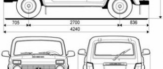
— Body clearances of the Niva 21213 car, diagram
— Connection diagram for direction indicators Niva 21213
Recommendations
I replaced the ignition switch contact group, now everything works as before!Thanks for the advice!
And also interesting: Do-it-yourself modifications to the Niva 2121 “
The dimensions from the factory work without ignition. I often forget to turn it off, I lock the car, and the lights are on and the lights are on. Of course there is no stove.
And in principle, you shouldn’t turn on the heater fan until you start the engine!
And my dash doesn't light up and the heater fan doesn't work when the ignition is off. How it should be!
The tidy should light up when the lights are turned on.
It doesn't light up for me. Only when the ignition is turned on.FLASH-X3!
Either there is a problem in the lock, or in the button for turning on the dimensions (headlights), there is simply nothing to break.
The heater fan will never run without ignition. Not provided.
The backlight has a power supply system independent of the ignition.
The key in the ignition switch must be turned to marks III and I. If the key is at mark 0, nothing will work. Even the light.
If the key is in the required (III and I) position and nothing works... there may be either problems with the lock or contact group, or the wires are mixed up when connecting, if the lock was turned off.
thanks, do you think it’s the ignition switch? I’m just leaning towards that too...
The heater fan will never run without ignition. Not provided.
The backlight has a power supply system independent of the ignition.
The key in the ignition switch must be turned to marks III and I. If the key is at mark 0, nothing will work. Even the light.
If the key is in the required (III and I) position and nothing works... there may be either problems with the lock or contact group, or the wires are mixed up when connecting, if the lock was turned off.
I have a 21st Niva
It doesn't matter what kind of field. The electrics on all classic vases are similar and unchanged. And the stove motor does not turn on without the ignition.
I understood why I thought it was turned on.
The heater fan will never run without ignition. Not provided.
The backlight has a power supply system independent of the ignition.
The key in the ignition switch must be turned to marks III and I. If the key is at mark 0, nothing will work. Even the light.
If the key is in the required (III and I) position and nothing works... there may be either problems with the lock or contact group, or the wires are mixed up when connecting, if the lock was turned off.
Without a key, I only have stoplights that light up when I press the brake pedal)
My car works halfway without a key.
The heater fan will never run without ignition. Not provided.
The backlight has a power supply system independent of the ignition.
The key in the ignition switch must be turned to marks III and I. If the key is at mark 0, nothing will work. Even the light.
If the key is in the required (III and I) position and nothing works... there may be either problems with the lock or contact group, or the wires are mixed up when connecting, if the lock was turned off.
The problem was solved by replacing the ignition switch contact group!thanks for the advice)
Read news about the new Niva
- Diagram and location of the fuse box Niva VAZ-21213 and 21214
- The modernized Lada Niva Legend (4x4) 2021 was shown on the Internet
- Lada 4×4 Bronto - sales stopped, new details » Lada.Online - all the most interesting and useful about LADA cars
- Description of the instrument panel Lada 4×4 (VAZ 2121, 2131) » Lada.Online - all the most interesting and useful about LADA cars
- LADA Niva – Operating manual – Official LADA website
- Chevrolet Niva gasoline consumption per 100 km
- Buy LADA (VAZ) 2131 (4×4) 2022 in Rostov-on-Don, low price for Lada 2131 (4×4) 2022 on the Avto.ru website
- Diagram and location of the fuse box Niva VAZ-21213 and 21214