Engine control system fuse box
Scheme
Designation
| 1 | 15A 1* ECM sensors Starter relay Canister purge valve |
| 1 | 7.5A 2* Controller |
| 1 | 3: Electric fuel pump relay (contacts) Electric fuel pump |
| 1 | 30A 4.5* Cooling fan |
| 2 | 15A 1* Injectors Ignition coils ECM controller Right electric fan relay Left electric fan relay |
| 2 | 15A 2* Electric fuel pump relay (contacts) Electric fuel pump |
| 2 | 30A 3* Reserve |
| 2 | 30A 4.5* Cooling fan |
| 3,4 | 30A 1* Electric fans (right, left) Right electric fan relay Left electric fan relay |
| 3 | 15A 2* Main relay |
| 3 | 15A 3* Controller |
| 3 | 15A 4* Ignition coil, power supply for fan relay control, controller, injectors |
| 3 | 15A 5* Ignition relay |
| 4 | 15A 3* Main relay Electric fan relay (winding) Electric fuel pump relay (winding) Vehicle speed sensor Canister solenoid valve Oxygen sensor Mass air flow sensor Controller |
| 4,5 | 30A 2* Electric fan relay (winding) (right, left) Electric fan motor (right, left) |
| 4 | 15A 4* Mass air flow sensor, phase sensor, heating oxygen sensor (two), canister purge valve, DS |
| 4 | 15A 5* Electric fuel pump |
| 5 | 15A 1* Electric fuel pump Electric fuel pump relay |
1* - 2021-2021, 2* - 2021-2021, 3* - 2007-2008, 4* - Cars with Bosch ME17.9.7/M74 controllers, 5* - Cars with 7.9.7 controllers.
Instrument harness connection diagrams
List of elements of the electrical connection diagram of the instrument panel wiring harness assembly for cars of the LADA 4X4 family
1 – additional relay; 2 – relay-interrupter of direction indicators; 3 – windshield wiper relay; 4 – ignition switch; 5 – alarm switch; 6 – rheostat 2130; 7 – turn signal headlight switch; 8 – windshield wiper and washer switch; 9 – main fuse block; 10 – additional fuse block; 11 – instrument clusters; 12 – external lighting switch; 13 – rear window wiper switch; 14 – rear window heating switch; 15 – rear fog light switch; 16 – heater motor switch; 17 – additional resistor of the heater electric motor; 18 – heater electric motor; 19 – relay for high beam headlights; 20 – low beam headlight relay: 21 – rear window heating relay; 22 – rear fog light relay: 23 – cigarette lighter; 24 – differential engagement sensor; 25 – brake signal switch; 26 – reverse lamp switch; 27 – handbrake warning lamp switch; 28 – illuminator; 29 – illuminator; 30 – instrument panel harness block to the front harness: 31 – instrument panel harness block to the front harness; 32 – block of the instrument panel harness to the ignition system harness; 33 – instrument panel harness block to the rear harness: 34 – instrument panel harness block to the rear harness.
A1, A2 – grounding points of the instrument panel wiring harness. A3 – grounding point of the heater motor. Instrument panel wiring harness assembly – 21214-3724030-60. Connection wire for additional resistor and heater electric motors for assembly - 2105-3724040.
List of elements of the electrical connection diagram of the front wiring harness assembly for cars of the LADA 4×4 family
1 – right headlight; 2 – additional starter relay; 3 – front harness block to the instrument panel harness; 4 – front harness block to instrument panel harness; 5 – coolant temperature sensor; 6 – oil pressure warning lamp sensor; 7 – sound signal; 8 – brake fluid level sensor; 9 – left headlight 2129; 10 – pads for the front harness and the harness for the sidelights and right side turn signal 11 – pads for the front harness and the wiper motor; 12 – windshield wiper motor; 13 – blocks of the front mudguard harness and connecting starter wire; 14 – starter; 15 – rechargeable battery; 16 – generator; 17 – connector 18 – electric washer motor; 19 – blocks of the front harness and the harness of the sidelight and left side turn signal; 20 – right side turn signal; 21 – right side headlight; 22 – left sidelight 2129; 23 – left side turn signal.
A1, A2 – grounding points of the front wiring harness. A3 is the grounding point for the hood ground wire. A4, A5 – grounding points and wires connecting the motor with the battery and housing. Front wiring harness assembly - 21214-3724010-71. Wiring harness for side headlight and right side turn signal assembly – 21213-3724020. Wiring harness for sidelight and side turn signal left assembly - 21213-3724021. Wire harness connecting battery and starter assembly - 21213-3724070-11. Connecting wire for the generator and front harness assembly - 21214-3724068. Connecting wire for starter and front harness assembly - 2101-3724060. Connecting wire for engine with battery and housing assembly 21214-3724080-21. Ground wire, hood assembly 21213-3724091
1 – rear harness pads to the instrument panel harness; 2 – rear harness pads to the instrument panel harness; 3 – rear harness block to the ignition system harness; 4 – interior lamp switch in the driver’s door pillar; 5 – switch for the interior lighting in the passenger door pillar; 6 – left interior lamp; 7 – right interior lamp; 8 – electric fuel pump with fuel level indicator sensor; 9 – rear window heating element; 10 – additional brake signal; 11 – right lamp; 12 – left lamp 2131; 13 – license plate light; 14 – license plate light; 15 – rear window wiper electric motor; 16 – rear window washer electric motor.
A1 – grounding point of the rear window heating ground wire. A2 – grounding point of the right lamp. A3 – grounding point of the left lamp. A4 – grounding point of the wiring harness of the license plate light housing. A5-A8 – grounding points of the rear wiring harness assembly. Rear wiring harness assembly – 2I214-3724210-10. Wiring harness for license plate light housing assembly - 21214-3724214. Ground wire for heated rear window 21214-3724094.
List of elements of the electrical connection diagram of the ignition system wiring harness assembly for cars of the LADA 4×4 family
1 – controller; 2 – electric fan of the engine cooling system, right; 3 – electric fan of the engine cooling system, left; 4 – block of the ignition system harness to the rear wiring harness (LADA4x4 (21214)); ignition system harness blocks to the fuel level sensor wiring harness (LADA 4×4 (2131)); 5 – control oxygen sensor; 6 – diagnostic oxygen sensor; 7 – system status indicator; 8 – APS-4 control unit; 9 – VAZ-2131 phase sensor; 10 – knock sensor; 11 – rough road sensor; 12 – diagnostic block; 13 – speed sensor; 14 – idle speed regulator; 15 – coolant temperature sensor; 16 – columnar shaft position sensor; 17 – solenoid valve for purge of the adsorber; 18 – mass air flow sensor; 19 – throttle position sensor; 20 – block of the ignition system harness to the instrument panel harness; 21 – ignition system harness connectors to the rear wiring harness and the interior light switch in the driver’s door pillar; 22 – ignition relay; 23 – electric fuel pump relay; 24 – left electric fan relay; 25 – right electric fan relay; 26 – ignition coil; 27 – spark plugs; 28 – nozzles; 29 – ECM fuse block; 30 – controller power supply fuse; 31 – terminal of the ignition system harness to the additional starter relay;. 32 – pads of the ignition system harness and injector harness.
Useful: Pinout of mounting blocks for VAZ cars
Al, A2 – to the “plus” terminal of the battery. Bl, B2, ВЗ – grounding points of the ignition system harness. Ignition system wiring harness assembly – 21214-3724026-97. Injector wiring harness assembly - 21214-3724036.
1 – rear harness block to the instrument panel harness; 2 – rear harness block to the instrument panel harness; 3 – switch for the interior lighting in the driver's door pillar; 4 – switch for the interior lighting in the pillar of the right front door; 5 – switch for the interior lighting in the pillar of the right rear door; 6 – switch for the interior lighting in the left rear door pillar; 7 – interior lamp; 8 – rear harness and fuel level sensor harness pads; 9 – rear window heating element; 10 – additional brake signal; 11 – right lamp; 12 – left lamp VAZ-2131; 13 – electric fuel pump with fuel level indicator sensor; 14 – rear harness block to the ignition system harness; 15 – license plate light; 16 – license plate light; 17 – rear window wiper electric motor; 18 – rear window washer electric motor.
A1 is the grounding point for the interior lamp. A2 – grounding point of the rear window heating ground wire. A3 – grounding point of the right lamp. A4 – grounding point of the left lamp. A5 – grounding point of the fuel level sensor wiring harness assembly. A6 – grounding point of the wiring harness of the license plate light housing. A7 – grounding point of the rear wiring harness assembly. Wiring harness for license plate light housing assembly -21214-3724214. Fuel level sensor wiring harness assembly – 2131-3724037 Rear wiring harness assembly – 2131-3724210-20. Ground wire for heated rear window 21214-3724094.
Schematic diagram of the instrument cluster
Block X1
- To terminal 15 of the ignition switch
- To the switch
- To the instrument lighting switch
- To the engine control system controller
- To the ground terminal “-“
- To terminal “50” of the ignition switch
- To brake fluid level sensor
- To emergency oil pressure sensor
- To differential lock sensor
- To terminal “W” of the fuel level sensor
- To seat belt relay
- To the parking brake warning switch
- Reserve
Block X2
- To the headlights (high beam)
- To the main light switch
- Reserve
- To turn signal relay
- To terminal “61” of the generator
- Reserve
- To temperature gauge sensor
- To the engine control system controller
- To terminal “T” of the fuel level sensor
- To the engine control system controller
- To the heated rear window switch
- To the rear fog light switch
- Reserve.
Engine Control Relay Box
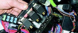
It is located under the main fuse box and consists of 5 relays and 1 fuse.
Scheme
Electrical diagram of the block
Decoding
- Ignition relay
- Main relay
- Right cooling fan relay
- Left cooling fan relay
- Fuel pump relay
- Fuel pump fuse F5 15A
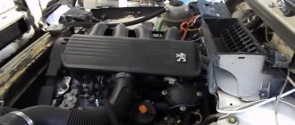
The only difference between Nivas with injection and carburetor systems is due to the fact that the engine control relay unit can be located under the hood of the car in a specially designated compartment.
Where are the blocks and relays located in Niva 21214 and 21213
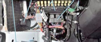
The main power supply in these models is located under the lower edge of the instrument panel protection. Additional fuses in Niva 21214 for the injector are located to the left. This block is responsible for controlling fuel injection. There are also relays for monitoring the operation of the wipers and a set responsible for the motion control system.
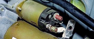
Another fuse box is installed in the body to the left of the main one. They are responsible for the cooling system and how the engine works. There is also a diagnostic connector. The relay that controls the starter is located either next to the main power supply, or under the hood next to the brake fluid reservoir.
Main fuse box
Scheme
Purpose
| 1 | 16A Heater fan electric motor Relay (winding) for headlight wipers and electric motors for headlight wipers in all wipe positions except the initial Relay (winding) for turning on the rear window heating Electric motors for the rear window cleaner and washer Electric motor for the windshield washer |
| 1* | 16A Lamps Horns Socket Lighter Brake light lamps |
| 2 | 8A Relay and electric motor of the windshield wiper Turn signal lamps and relay-interrupter for direction indicators and hazard warning lights (in turn signal mode) Turn signal indicator lamp Tail lights (reversing light lamps) Generator excitation winding (when starting the engine) Differential lock activation indicator lamp in the transfer case Indicator lamp for turning on the parking brake Indicator lamp for the emergency condition of the service brake system Indicator lamp for insufficient oil pressure Fluid temperature indicator in the engine cooling system Fuel level indicator with a warning lamp for fuel reserve Indicator lamp for battery charge Indicator lamp for closing the carburetor air damper Tachometer Electric heater motor Relay headlight cleaners and washer (with the headlight cleaner and washer switch button not pressed) Headlight wiper electric motors in all brush positions except the initial one* |
| 3 | 8A Left headlight (high beam lamp) Indicator lamp for turning on the high beam headlights |
| 4 | 8A Right headlight (high beam lamp) |
| 5 | 8A Left headlight (low beam) |
| 6 | 8A Right headlight (low beam) |
| 7 | 8A Left front light (side light) Right rear light (side light) License plate lights Indicator lamp for turning on side lights |
| 8 | 8A Right front light (side light) Left rear light (side light) Instrument lighting lamp Heater control lever backlighting lamp Cigarette lighter lighting lamp Illumination lamps for switches and switches |
| 9 | 16A Direction indicators and relay-breaker for direction indicators and hazard warning lights Rear window heating element and relay (contacts) for its activation |
| 9* | 8A Warning lamp and oil pressure gauge Coolant temperature gauge Fuel level gauge with reserve warning lamp Parking brake warning lamp Brake fluid level warning lamp Turn indicators and corresponding warning lamp Carburetor choke control warning lamp Battery charge warning lamp Carburetor shut-off valve Tachometer Rear lights (reverse light) Differential lock warning lamp Turn signal relay interrupter Heated rear window (control circuit) |
| 10 | 16A Sound signal Cartridge for connecting a portable lamp Interior lamps Tail lights (brake lamps) |
| 10* | 8A Voltage regulator Generator excitation winding |
| 11 | 8A Turn signal lamps and relay-breaker for turn signals and hazard warning lights (in hazard warning mode) Rear fog lamp |
| 12 | 8A Daytime running light relay, daytime running light lamps |
| 12* | 8A Headlight cleaner and washer relay (with the headlight cleaner and washer switch button pressed) Headlight washer electric motor Headlight cleaner electric motors at the moment of start-up and when the brushes pass the initial position |
| 13 | 8A Rear lights (fog light lamps) Electric motors for headlight cleaners at the time of start-up and when the brushes pass the initial position Relays (contacts) for headlight cleaners Electric motor for headlight washers |
| 14 | 16A Cigarette lighter |
| 15 | 16A Backup Heated rear window (power circuit) |
| 16* | 8A Hazard warning switch and direction indicators in hazard warning mode Rear window wiper and washer |
Also interesting: Chevrolet Niva |
VAZ 2123 from 2001, front brake instructions online. Fuse number 14 or number 1 at 16A is responsible for the operation of the cigarette lighter, depending on the year of manufacture.
Fuse box VAZ Niva old and new model
The main difference between the schemes of old and new Niva lies in the method of connecting the additional mounting block, which is located below.
If in older models only two fuses are used for this purpose, then in the updated ones there are already four. In general terms, the difference between the two blocks looks like this:
| New additional block | Old additional block | ||||
| Fuse no. | Current (amps) | What is he responsible for? | Fuse no. | Current (amps) | What is he responsible for? |
| 11 | 8 | Turn signal lamps, relay-breaker for turn signals and emergency lights | 11 | 8 | Reserve |
| 12 | 8 | Daytime running light relay, Daytime running light bulbs | 12 | 8 | Reserve |
| 13 | 8 | Rear fog lights and their relay | 13 | 8 | Fog lights and their relays |
| 14 | 16 | Cigarette lighter | 14 | 16 | Cigarette lighter |
| 15 | 16 | Reserve | 15 | 16 | Reserve |
| 16 | 8 | Reserve | 16 | 8 | Reserve |
Additional relay block
This block is located above the gas pedal.
Scheme
Description
- Rear fog lamp relay
- Rear window heating relay
- Low beam relay
- High beam relay
A little higher, above the block, a relay can be installed - a breaker for the turn signals and hazard warning lights.
Separate fuses and relays can be installed under the hood: on cars with ABS, on the left side of the engine compartment near the ABS hydraulic unit, a block with fuses is additionally installed that protect the elements of the anti-lock brake system and the starter relay not far from the starter itself.
Types of fuses
Over the entire period of its existence, this segment of car elements has changed more than one type. The most common ones are:
Flat fuses are considered a relatively new type. They are used in almost all new cars. They became widespread due to their increased level of reliability and relatively low cost.
The next item will be ceramic fuses, which used to be very popular, but have lost their position due to low efficiency.
The oldest of all types of fuses are glass. They are small cones made of glass. This type of fuses is practically not used today due to the low level of reliability.
These are the most common types of fuses, however, there are others, but less popular.
DIY power supply replacement
Below we will look at the process of replacing the power supply with your own hands. To replace, you will need a new power supply and a socket head set to “8”.
- First, open the hood and disconnect the battery.
- Now, under the instrument panel, find your power supplies. Using an “8” socket wrench, unscrew the two main nuts.
- Having done this, pry up the power supply and remove them from the studs.
- If you are replacing an old component with a new one, you must mark all the wires before doing so. Or take a new power supply unit and insert the wires from the old unit into it one by one. To remove the idle wires, pull them by their plugs.
- To check the functionality of the new power supply, reconnect the battery.
Replacement
In the event of a breakdown, the fuses must be replaced in time to avoid serious problems with important components of the car in the future. The replacement process is quite simple. To do this, you simply need to remove the blown fuse and replace it with a new one.
Thus, further proper operation of the circuit for which he is responsible will be established. A very important nuance is the full compliance of the fuses (blown and new) regarding their markings and the output voltage. Otherwise, if this aspect is not taken into account, any of the elements included in the circuit that this fuse protects may burn out.
As a result, it must be said that the fuse is one of the most important parts in any car and Niva-21214 is no exception. In this regard, it is recommended to constantly monitor the condition of the mounting block and fuses. After all, if their work proceeds without any failures, then the risk of any serious electrical malfunction is reduced to almost a minimum. Thus, the key to a successful motorist is careful care of his car, and, of course, timely repair of all its components, including fuses.
Replacing fuse Lada 2131 (VAZ 2131)
Every car has a fuse box that is responsible for the operation of certain components of the vehicle. If certain fuses fail, the operation of some elements becomes impossible, but if the unit itself breaks down, the vehicle simply will not be able to continue moving.
The fuse block (hereinafter referred to as the fuse block), unlike traditional models of the domestic automobile industry, is located in the vehicle interior. In particular, it is located on the driver's side under the steering wheel.
If any electrical circuit element in a car stops working (lamps, interior lights, heater, power windows), then car owners first check the power supply elements.
As a rule, the problem is resolved by replacing the fuse.
What does the power supply circuit itself look like? This question may be of interest to Niva owners. Below we will look at the electrical circuit of the unit with a description of all the components responsible for the operation of certain devices in the car.
In accordance with the diagram, we will consider the meaning of the BP elements. This electrical circuit is universal for all Niva cars.
It should also be noted that in VAZ 21214 injector cars there is another power supply unit with injection system components. It is located separately from the main power supply on the left side under the steering wheel.
In the case of the first described power supply unit, if the elements of the device begin to fail, this will in no way threaten the performance of the car, of course, with the exception of breakdowns of some components. However, in the case of the second power supply, if at least one component shorts out and does not work, the VAZ 21214 injector engine will not start.
Fuses for Niva 21214
Today, almost every person has a personal car, and, of course, at the moment it is difficult to imagine our life without a car.
Thanks to it, we can move around the city or highway without any restrictions. However, situations very often occur when something breaks down in a car. No matter how sad it may sound, in cars from the VAZ company various parts break very often, and sometimes you have to fix them yourself, because prices at car dealerships are quite high. This article will look at fuses on Niva 21214 cars with an injector engine, how to repair or replace them.
Fuses are one of the most important parts in any car, as it is thanks to them that the vehicle does not suffer any significant damage. In addition, fuses are precisely those elements of the Niva that, in the event of any voltage drop in the electrical circuit, take the entire blow, preventing the occurrence of serious malfunctions. A very important, however, very fragile part that very often fails, which is why it has to be replaced. The process of replacing or repairing a fuse is extremely simple and does not require special professional skills or tools.
Mounting blocks for lada 4×4 2021
The main and additional units are located in the cabin to the left of the steering wheel, under the instrument panel. The blocks contain fuses of the “Cylinder” size, ten and six fuses, respectively. The ratings and purpose of the fuses are indicated in Table 4 “Circuits protected by fuses”:
Fuse block of standard size “Standard”. The block is located on the left side under the upholstery and contains fuses that are designed to protect engine control system devices. The ratings and purpose of the fuses are shown in Table 5:
The fuse and relay box is located on the left side of the steering column under the instrument panel. The block contains two “Standard” size fuses, which are designed to protect the circuits of the electric fuel pump, electric windows and electric mirrors. The ratings and purpose of the fuses are shown in Table 6:
The fuse and relay box is located on the right side of the steering column under the instrument panel. The block contains one “Maxi” size fuse and two “Standard” size fuses, which are designed to protect the circuits of the hydraulic unit of the anti-lock braking system. The ratings and purpose of the fuses are shown in Table 7:
Fuse diagram Niva 2131 injector
All vehicles have a block in which protective inserts for the electrical circuit are located. VAZ 21214 fuses on the Niva injector are installed in several places. In addition, the block diagram has its own nuances associated with the great age of the car design.
Where are the fuse and relay boxes located?
Designation and electrical diagram of the main and additional power supply
Engine control system fuses
Engine Control Relay Box
Relay block diagram above the gas pedal
Video “Replacing fuses on Niva 4x4”
Purpose of fuses, relays and their replacement Niva VAZ 21213, 21214, 2131 lada 4×4
Note. Keep in mind that the location and purpose of fuses has changed and continues to change, depending on the year of manufacture and modification of the car. This page presents several options, be careful!
If the fuse fails again, contact your LADA dealer to find out and eliminate the reasons that caused it to melt.
It is unacceptable to install a homemade jumper or a fuse of a different rating to replace the blown one.
Content:
Fuse locations in the interior and under the hood (from 2020) Main fuse locations (until 2022) Additional relay boxes Additional fuses and relays for vehicles with ECM Additional fuses for vehicles with ABS Additional fuses for Urban equipment Replacement of fuses
Also interesting: Engine twitching at idle: causes of malfunction "
Fuse and relay locations (from 2022)
Fuses and relays are located in two blocks: in the passenger compartment (Fig. 48) and in the engine compartment (Fig. 49).
When replacing fuses and relays, use only new fuses and relays that are marked in accordance with tables 1 and 2. To avoid melting of the insulation of the wires and the housing of the mounting block when operating the vehicle, you should use only types of fuses and relays approved for use by AVTOVAZ JSC, according to Tables 1 and 2.
Fuse and relay box in the passenger compartment
Rice. 50. Diagram of the mounting block in the cabin with numbering of fuses and relays
Table 1
| FUSES IN THE PASSENGER BLOCK | ||
| Fuse number | Denomination | Protected Circuits |
| F12 | 7.5A | Power supply for air flow sensor, phase sensor, upper and lower oxygen sensors, canister purge valve |
| F13 | 15A | Power supply for the rear wiper and washers of the front and rear windows |
| F14 | 15A | Power socket 12 V trunk |
| F15 | 15A | Power supply for front seat heaters |
| F16 | 25A | Power supply for front windows and side mirror controls |
| F17 | 15A | Front wiper power supply |
| F18 | 15A | Radio power supply |
| F19 | 20A | Power supply for the first and second 12 V sockets in the cabin |
| F20 | 15A | Air conditioner clutch power supply |
| F21 | 5A | Power supply K15 for ABS hydraulic unit |
| F22 | 20A | Rear window defroster power supply |
| F23 | 20A | Power supply for interior heater fan |
| F24 | 5A | Power supply for reverse lamp and K15 radio signal |
| F25 | 10A | Power supply for hazard warning lights and instrument cluster |
| F26 | 7.5A | Signal K15 alarm and instrument cluster |
| F27 | 7.5A | Power supply unit SNPB |
| F28 | 5A | Brake and clutch switch signal |
| F29 | 15A | Power supply for fuel pump and diagnostic connector |
| F30 | 10A | Power supply for rear fog lights |
| F31 | 7.5A | Power supply for fog lights |
| F32 | 10A | Power supply for left side lights, license plate light and trunk light |
| F33 | 7.5A | Power supply for right side lights and interior illumination of controls |
| F34 | 10A | Power supply for daytime running lights (DRL) |
| F35 | 10A | Power supply for the DS lamp of the left headlight |
| F36 | 10A | Power supply for the BS lamp of the left headlight |
| F37 | 10A | Power supply for the BS lamp of the right headlight |
| F38 | 10A | Power supply for the right headlight DS lamp |
| F39 | 5A | Air conditioner panel power |
| F40 | 7.5A | Power supply for side mirror heaters |
| F41 | 7.5A | Power supply for brake lights and DST |
| F42 | 5A | Power supply for interior lighting |
| RELAY IN THE SALON BLOCK | ||
| Relay number | Denomination | Relay purpose |
| K5 | Z0A | Starter activation relay |
| KB | 40A | Ignition switch unloading relay |
| K7 | 20A | Left and right headlight switch relay |
| K8 | 20A | Relay for turning on BS left and right headlights |
| K9 | 20A | Fuel pump relay |
| K10 | 20A | ECM main relay |
| K11 | 20A | Front seat heating relay |
| K12 | 20A | Air conditioning clutch activation relay |
| K13 | 20A | Heater fan relay |
| K14 | 20A | Left DRL activation relay |
| K15 | 20A | Right DRL activation relay |
| K16 | 20A | Heated rear window relay |
Fuse and relay box in the engine compartment
Rice. 51. Diagram of the mounting block in the engine compartment with numbering of fuses and relays
table 2
| FUSES IN THE ENGINE COMPARTMENT BLOCK | ||
| Fuse number | Denomination | Protected Circuits |
| F1 | 60A | Battery protection against generator short circuit |
| F2 | 60A | Battery protection against generator short circuit |
| F3 | 40A | Power supply to the interior mounting block |
| F4 | 40A | Power supply for hydraulic pump of ABS hydraulic unit |
| F5 | 30A | Top Radiator Fan Power |
| F6 | 30A | Lower radiator fan power supply |
| F7 | 25A | Power supply for ABS hydraulic unit solenoid valves |
| F8 | 25A | General power supply for external lighting equipment |
| F9 | 20A | ECM power supply |
| F10 | 15A | Horn power supply |
| RELAY IN ENGINE COMPARTMENT | ||
| Relay number | Denomination | Relay purpose |
| K1 | 40A | Top fan relay 1 |
| K2 | 40A | Relay 2 for switching on the top fan |
| KZ (yellow) | 40A | Relay 3 for turning on the lower fan |
Fuse protected circuits (until 2022)
Fuses do not protect the electrical circuits of ignition, engine start, generator (except for the field winding), low beam headlight relay, high beam headlight relay.
Please note that the rating and purpose of fuses may vary depending on the year of manufacture of the vehicle. Therefore, explanatory tables 3 and 4 are presented in two versions.
Most fuses are located in blocks located in the passenger compartment under the instrument panel, to the left of the steering column. The fuses are installed in two blocks side by side, they are connected to each other (Fig. 44) and are held in them by spring contacts. There are ten fuses in the upper block and six fuses in the lower block. The circuits they protect are listed in Table 3.
Rice. 44. Fuses (appointment is indicated in table 3)
Additional fuse and relay blocks
Relay block under the instrument panel, above the gas pedal: 1 - rear fog light relay; 2 — relay for turning on the heated glass of the luggage compartment door; 3 — low beam headlight relay; 4 - high beam headlight relay
Additional blocks for vehicles with ECM
On vehicles with an ECM, a block (Fig. 45) with four fuses is additionally installed on the left side of the front end under the instrument panel, which protect the elements of the injection systems. (to the right of them is the diagnostic connector) A faulty fuse is determined by the failed circuits that it protects, in accordance with Table 4.
TABLE 4 (for Fig. 45)
To connect and protect the ECM circuits, a “safety line” type wire is used, which is part of the ignition system wiring harness and is connected directly to the battery. The circuits protected by this wire are listed in Table 5.
Table 5
| Fuse | Protected circuit |
| Safety line type wire | ECM main relay |
| Diagnostic block | |
| APS | |
| Fuses 1, 2, 5 of the injection system (see table 4, 2nd option) |
On vehicles with ABS, a fuse block is additionally installed on the left side of the engine compartment near the ABS hydraulic unit, which protects the elements of the anti-lock brake system. Fuse ratings are shown in Table 6.
And also interesting: LADA Niva Legend 3 doors. from 619,900 rub. – Prices and configurations – JSC Autocentre-Tolyatti-VAZ: LADA dealer in Togliatti
Table 6
In the LADA 4×4 Urban configuration, the electrical equipment has additional circuits protected by fuses, the list of which is indicated in Table 7. And the list of main fuses is the same as for the regular LADA 4×4 configuration.
Table 7 (additional fuse circuits in the Urban package)
* For LADA 4×4 Urban cars. ** For LADA 4×4 vehicles with air conditioning.
Disconnect the negative cable from the battery. By pulling the latch located on top of the main fuse box cover...
Similarly, remove the cover of the additional fuse box.
Video
Fuse arrangement in a Niva 21214 car
In Niva 21214, the fuse device has a rather non-standard appearance. There is a spare one under the main fuse box, which takes over its role if the main one breaks down. Also, this car has a slightly changed role of fuses in the chain of operation, namely in their purpose. The table shows several similar examples of fuses with descriptions.
| Fuse name | Protected circuit |
| F1 | Responsible for the operation of the dimensions, license plate, lighting of the glove compartment and luggage compartment. |
| F2 | Responsible for the steering column switch. |
| F3 | Seat heating fuse. |
| F4 | Responsible for the fog lights on the left side. |
| F5 | Fuse for power windows. |
| F6 | Responsible for portable lighting. |
| F7 | Responsible for the engine cooling fan and the operation of the sound signal. |
| F8 | Responsible for the cigarette lighter. |
| F9 | Regulates the operation of the recirculation unit and the cleaning of the windshield. |
| F10 | Backup fuse can be used to charge the battery. |
| F19 | Operation of the central locking system, alternator winding, reversing lights and brake light. |
For a more detailed study, you should familiarize yourself with a more structured diagram.
This car also has a second unit, which is located above the gas pedal and includes 4 relays responsible for: interior light, proper operation of the rear lights, rear window heating switch, wipers, high and low beam.
In addition, the car has a relay unit responsible for engine control. The elements of this block are: relay for the starter, fuel pump (fuel pump), cooling fan (right and left) and the main master relay.
Diagram for switching on the dimensions of the Niva 21213 car |
Scheme for switching on the external lighting (dimensions) of the Niva 21213 car
Elements of the diagram for switching on the dimensions of the Niva 21213 car
1. Side lamps in the front lights of the car. 2.Fuse block. 3.Outdoor lighting switch. 4. Instrument lighting switch. 5. Indicator lamp for turning on the dimensions in the instrument cluster. 6.License plate lights. 7. Side light lamps in the rear lights.
A - to the lighting lamps of the instrument cluster, switches and backlight display.
Notes and additions
More diagrams of the Niva 21213 car
— Connection diagram for low and high beam headlights Niva 21213
— Wires for the rear lights of the Niva 21213 car, diagram
— Connection diagram for generator 9412.3701 for Niva 21214
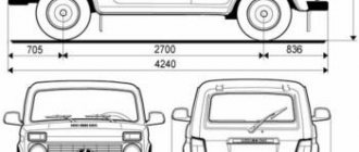
— Body clearances of the Niva 21213 car, diagram
— Connection diagram for direction indicators Niva 21213
Designation and electrical diagram of the main and additional power supply
The designations and explanations of the fuses of the main and additional units are printed on the surfaces of the covers.
Diagram of the main and additional blocks
Description of the fuses in the upper main section of the VAZ 212214 Niva injector.
| Number on the diagram | Rated current, A | Purpose |
| PR01 | 16 | Heater fan motor, front glass fluid supply system, rear wiper motor |
| PR02 | 8 | Front wiper, direction indicators (with relay), switch block under the steering wheel, instrument cluster instruments and lamps, reverse indicator lamps |
| PR03 | 8 | High beam in the left headlight and high beam indicator lamp in the instrument cluster |
| PR04 | 8 | High beam for right headlight |
| PR05 | 8 | Low beam left |
| PR06 | 8 | Same as on the right |
| PR07 | 8 | Left side dimensions, registration plate illumination, dimensions indication on the instrument cluster |
| PR08 | 8 | Right dimensions and illumination of control devices |
| PR09 | 8 | Hazard warning relay circuit and activation button, rear defogger system |
| PR10 | 8 | Horn, interior lighting and brake lights (all three) |
Recommendations
I replaced the ignition switch contact group, now everything works as before!Thanks for the advice!
And also interesting: Do-it-yourself modifications to the Niva 2121 “
The dimensions from the factory work without ignition. I often forget to turn it off, I lock the car, and the lights are on and the lights are on. Of course there is no stove.
And in principle, you shouldn’t turn on the heater fan until you start the engine!
And my dash doesn't light up and the heater fan doesn't work when the ignition is off. How it should be!
The tidy should light up when the lights are turned on.
It doesn't light up for me. Only when the ignition is turned on.FLASH-X3!
Either there is a problem in the lock, or in the button for turning on the dimensions (headlights), there is simply nothing to break.
The heater fan will never run without ignition. Not provided.
The backlight has a power supply system independent of the ignition.
The key in the ignition switch must be turned to marks III and I. If the key is at mark 0, nothing will work. Even the light.
If the key is in the required (III and I) position and nothing works... there may be either problems with the lock or contact group, or the wires are mixed up when connecting, if the lock was turned off.
thanks, do you think it’s the ignition switch? I’m just leaning towards that too...
The heater fan will never run without ignition. Not provided.
The backlight has a power supply system independent of the ignition.
The key in the ignition switch must be turned to marks III and I. If the key is at mark 0, nothing will work. Even the light.
If the key is in the required (III and I) position and nothing works... there may be either problems with the lock or contact group, or the wires are mixed up when connecting, if the lock was turned off.
I have a 21st Niva
It doesn't matter what kind of field. The electrics on all classic vases are similar and unchanged. And the stove motor does not turn on without the ignition.
I understood why I thought it was turned on.
The heater fan will never run without ignition. Not provided.
The backlight has a power supply system independent of the ignition.
The key in the ignition switch must be turned to marks III and I. If the key is at mark 0, nothing will work. Even the light.
If the key is in the required (III and I) position and nothing works... there may be either problems with the lock or contact group, or the wires are mixed up when connecting, if the lock was turned off.
Without a key, I only have stoplights that light up when I press the brake pedal)
My car works halfway without a key.
The heater fan will never run without ignition. Not provided.
The backlight has a power supply system independent of the ignition.
The key in the ignition switch must be turned to marks III and I. If the key is at mark 0, nothing will work. Even the light.
If the key is in the required (III and I) position and nothing works... there may be either problems with the lock or contact group, or the wires are mixed up when connecting, if the lock was turned off.
The problem was solved by replacing the ignition switch contact group!thanks for the advice)
Read news about the new Niva
- Diagram and location of the fuse box Niva VAZ-21213 and 21214
- The modernized Lada Niva Legend (4x4) 2021 was shown on the Internet
- Lada 4×4 Bronto - sales stopped, new details » Lada.Online - all the most interesting and useful about LADA cars
- Description of the instrument panel Lada 4×4 (VAZ 2121, 2131) » Lada.Online - all the most interesting and useful about LADA cars
- LADA Niva – Operating manual – Official LADA website
- Chevrolet Niva gasoline consumption per 100 km
- Buy LADA (VAZ) 2131 (4×4) 2022 in Rostov-on-Don, low price for Lada 2131 (4×4) 2022 on the Avto.ru website
- Diagram and location of the fuse box Niva VAZ-21213 and 21214
Maintenance of wiring VAZ 21214 and other Niva models injector and carburetor: electrical diagram
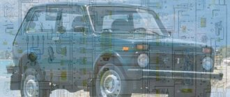
Every modern car today is equipped with an electrical part. The electrical diagram of the VAZ 21214 Niva injector allows, if necessary, to find all the elements included in the on-board network, which is especially important when faults occur in the wiring. Everything a driver needs to know about electrics in domestic SUVs is described in this article.
Detailed electrical diagram of Niva
The wiring diagram may vary slightly depending on the design features of the vehicle.
First, let's look at the index notation:
- VAZ 21213. This index designates a vehicle equipped with a carburetor. The volume of the power unit is 1.7 liters.
- 21214. In VAZ 21214 cars, the scheme involves the use of a similar engine with the same volume. The only difference is that the car is equipped with a fuel injection system.
- There is another model with the index 21213. In VAZ 21213 cars, the electrical circuit includes the same elements, only depending on the year of manufacture, the car can be equipped with a 1.8 liter engine.
- Version 21073. The SUV is equipped with either an injection engine with nozzles or a Solex carburetor engine. One of the features of these cars is a contactless ignition circuit.
- 21215. These SUVs were originally produced for export, so these cars are difficult to find on our roads. It is worth noting that they were equipped with Citroen diesel engines.
At the beginning of the article there is a diagram of the VAZ electrical equipment using the example of the Niva 2121 model. If you are the owner of version 2131 or any other, then there will be a difference in the circuit diagram, but not fundamentally. If we are talking about carburetor engines, then in this case the battery charging circuit, as well as the ignition, will not be protected (video author - Nail Poroshin).
Features of electrical equipment
The electrical circuit of the VAZ model 21213 has certain differences with the model 2121, in particular:
- 21213 vehicles use more modernized foot fuses in the fuse box. Of course, the use of such devices led to the fact that the block site also became different.
- The power supply system of these vehicles additionally includes an idle speed saving device. For this option to work properly, another connector with wiring was added in the engine compartment.
- Another difference is that these cars use a non-contact ignition circuit, the main element of which is a microcontroller.
It should be noted that differences in the Niva circuit may lie both in the generator units and in the electrics themselves.
Differences in generators
In any case, the differences in the wiring diagram of the models will primarily depend on the power unit - carburetor or injection.
The main differences in carburetors:
- models 21213 use the generator unit model 371.3701;
- in the engines of models 21214, the manufacturer decided to install a more powerful generator device; it is marked with the numbers 9412.3701 (video author - Sergei Chekhonin).
And although these generators are different, they have certain similarities in design. In any case, it is a synchronous AC device. In addition, these units have a built-in rectifier and output voltage regulation mechanism.
Wiring differences
If we talk directly about wiring, then depending on the car model, it may also have differences. It should be noted that these differences greatly simplify do-it-yourself maintenance and repair of the system. As for injection modifications of SUVs specifically, in this case the system is equipped with three outputs intended for installing electronic ignition.
In addition, 21214 cars use two ventilating devices that perform the function of cooling the radiator assembly. Accordingly, due to the use of additional fans, the wiring also underwent, albeit not significant, differences. Of course, they are not fundamental.