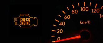
A car's tachometer is an important element for monitoring technical parameters. The article describes how to connect a tachometer to a VAZ-2109 with a carburetor engine.
Malfunctions of this device, methods for eliminating them, and a connection diagram to the electrical circuit of the car will also be considered.
To help the car enthusiast: tachometer connection diagram for VAZ 2109 carburetor
What is a tachometer? What is the connection diagram for the tachometer on a VAZ 2109 carburetor? A tachometer is a technical device that displays the number of revolutions of the engine crankshaft. The device shows not only engine speed. Modern developments inform the driver about fuel consumption and recommend a more optimal driving mode. There are devices with other functions. These are usually electronic models.
Principle of operation
The tachometer on the VAZ-2109 was installed only on versions with high and “euro” panels. On cars with a “Euro” panel, the tachometer is often of an electronic type, and works in conjunction with the control unit. Models with a low panel did not have such a device. The driver had to control the speed of the power unit by ear.
The system works according to the following principle:
- The ignition coil receives electrical voltage and equalizes it, converting voltage up to 35 thousand volts.
- The car distributor converts voltage into pulsed current due to the contact method of supplying voltage.
- These signals are sent to the tachometer pulse contact.
- At the back of the device there is an inductance coil, which, depending on the magnitude of the pulse current voltage, creates a magnetic field. The created magnetic field deflects the needle of the device due to the movement of the coil itself.
On carburetor cars, the distributor creates exactly 2 electrical impulses per full revolution of the crankshaft on power units with 4 pistons. This is worth taking into account, since installing the device from a 6-cylinder car will introduce a large percentage of error into the measurement of the number of revolutions.
The system is very simple and analog. Its operation is not affected by various sensors or third-party circuit components. But this system is not without its shortcomings. Next, the main malfunctions of the VAZ-2109 tachometer will be described.
How to Connect a Tachometer to a VAZ 2108 Carburetor
Connect the tachometer to the VAZ 2109 (carburetor)
Tachometer. This device is used to display the number of revolutions the crankshaft makes. While conventional entry-level tachometers just reported this, modern models are equipped with additional features that are useful to the driver: fuel consumption, recommendations for optimal driving conditions, etc.
What can you get
The best solution for owners of nine top and bottom panels. This is to buy new modern computing equipment and install it as a freelance device on the VAZ 2109. This will provide additional information and a little more to decorate the interior of your car,
But before you go to the hardware store, you should learn about the types of tachometers.
Types
Features of work
For diesel engines
Diesel engines are not equipped with ignition coils, since the tachometer works based on the readings of the generator pulses.
For gasoline engines
There are gasoline power units ignition coils
, whose current pulses are read by the tachometer. Therefore, the panel provides relevant information. Gasoline tachometers differ from each other depending on the number of cylinders in the engine
When purchasing a tachometer for your vehicle, be sure to specify that it is a four-cylinder gasoline power unit. Or just say you need a device for nine.
Own device. nothing special
Price issue
Device cost. This is an always debated issue. Some people believe that it is useless to buy expensive equipment, because all spare parts for VAZ are available and cheap.
But buying a cheap tachometer involves obtaining inaccurate information. Available devices may have 20-30% errors. The idea is to install such equipment if the data is still not true and the real benefits of the device you are not getting?
On average, a good tachometer for a VAZ 2109 will cost 1000-2000 rubles. Not a lot of money to save. By installing it yourself, the entire setup will cost the largest number of readers. And we will tell you in detail how to install it.
installation
Installation of tachometer VAZ 2108
DIY customization of VAZ 2108 (tachometer from 06 to 2108)
This video describes how to install a tachometer
six to six
2108
, 2109, 2199.
Everyone has a tachometer in your hands, so you can safely take it to your garage and start connecting the device.
You don't have to be afraid of DIY. Although the tachometer is an electrical device, it has three wires. Therefore, even inexperienced drivers can easily cope with the task.
Connection agreement is not an issue
Determine in advance where your engine speed reader will be located. Here the choice is entirely yours. Some are mounted directly on the dashboard, while others. next to the ignition switch. Try to choose a site where the device does not interfere and will not spoil the appearance of the salon.
The location has been decided so you can start safely.
- Remove the tachometer from the cab from the passenger compartment to the engine compartment. Practice shows that it is most convenient to remove it from the hole intended for the speedometer cable.
- To make the task easier, take a heavy but fairly thin wire. It takes about a meter in length. Connect the tachometer to one end using an extension cord. Just do it carefully so it can fit through the speedometer hole.
- Insert the other end of the wire into the socket and begin to remove it. Therefore, without unnecessary hassle, you extend the wiring into the engine compartment.
- Distribute the wires. 12. B ignition coil, signal. ignition coil but minus. the weight of your vehicle in any accessible or convenient location. For reliability, make sure that the weight can be increased with a nut.
- Even with high quality tachometers, the wires in the cable are thin and fragile. To prevent this from happening, solder full high quality wires to the device in 1 square wire. Try to find wires that match standard tachometer wiring colors. Then, on the other side of the wire, 1 square millimeter, install the lugs.
- Unscrew the mounting nuts on the ignition coil using a 10mm wrench, and then connect the wiring as shown in the figure.
- Tighten the nut, just pull it, showing that its strength is not worth it. Otherwise, you risk breaking the thread, and eliminating such a defect is problematic.
- Connect the ground. To do this, select a section where there is no wire that will interfere
, will not interact with other devices, will not overheat, etc. - Make sure your device is working. To do this, turn on the ignition. At the same time, the tachometer should show a proud 0. This means that the elevator is now zero and the crankshaft is not rotating.
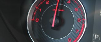
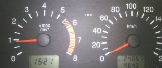
- Start a car. At idle the normal speed for the VAZ 2109 is 750-850 rpm. The relevant information should appear on the device in the cockpit.
- If the tachometer has the additional function of a voltmeter (a very useful function for those who prefer to independently repair and diagnose their cars). When selecting a voltmeter, the mains voltage should be displayed. about 11-12 V when the battery is properly charged.
Everything on this tachometer setup can be considered complete. There is nothing complicated in this process, so even a beginner can do this job.
VAZ 2109 cars and tachometer
All modern cars have tachometers of various types. VAZ 2109 models with a low panel do not have this smart device. Cars with a high panel have this device, but its quality and operating efficiency are far from what car enthusiasts expect. Therefore, the optimal solution for owners of such vehicles would be to purchase and install a new device. It doesn’t matter at all whether the car’s panel is low or high. It can be installed in a place where it will not only provide additional information, but also decorate the car interior. Before purchasing a device, you need to become thoroughly familiar with its types.
Cars with diesel engines are equipped with tachometers that read current pulses from the generator.
Gasoline units have ignition coils. The impulses arising on them are read by the tachometer. The devices have slightly different structures. This depends on the number of working cylinders in the engine. When purchasing a device, be sure to mention the number of cylinders. It is enough to simply inform the seller that you need a tachometer for a VAZ 2109. Many are interested in the cost of the product. Some car owners feel that there is no point in purchasing expensive parts when they can find cheaper analogues. Cheapness in relation to a tachometer can result in the device providing information with distortions that can reach 20 and even 30%. You will not get any real benefit from such a device.
A good device for a car can be purchased for about 1000-2000 rubles. It is quite difficult to save anything at such prices. And even a beginner can install the device with his own hands. Thus, all car tuning will be reduced to the cost of the device.
Installing a tachometer
You bought and brought home a new tachometer. Now you can go to your garage to install the device on a car that has a carburetor. Installing and connecting it is not that difficult. This is an electric device, but don't be afraid of it. How to connect it? The tachometer connection diagram is extremely simple. Even a less experienced person can easily connect the 3 wires coming from the device. So let's get started. You should:
- choose a location for the device in the car;
- lead the wires out of the passenger compartment into the space under the hood;
- distribute the wires on the ignition coil and on the ground of the car;
- check the operation of the device.
The choice of location is up to you. You can install a tachometer on the instrument panel or next to the ignition switch. As long as the device does not interfere with the driver and does not spoil the appearance of the interior. Then the wires are brought out. The best way to do this is through the hole through which the speedometer cable passes. To help, you can take a meter-long piece of rigid, but rather thin wire.
The cable coming from the tachometer is wound to the end of the wire with electrical tape so that it passes through the hole. In this way, you can run all the wires under the hood without any problems. Connect wire 12 to terminal B, the signal to terminal K. For the negative one, you need to find a suitable place on the ground of the car. It is better to tighten it with a nut.
Tachometer in low panel
Sooner or later, probably, any pelvic driver will want to put a tachometer in a low panel.
As you know, there are dial and digital tachometers. In the case of dial gauges, usually the Chinese tachometer is screwed directly to the panel with a self-tapping screw, or they put a huge tachometer from 2106 in some kind of bucket, coat it with all sorts of epoxies, in short it turns out scary, and also blocks the view if attached to a rack.
Well, the electronic one is simply attached with double-sided tape to the steering rack casing - it looks like something out of the ordinary, and somehow cheap.
But there were also a couple of photos on the Internet where an electronic tachometer was installed directly into the dashboard:
I really liked this option - in the place where it is needed, the visibility is excellent, when I saw this option it just seemed to me that without this screen the original instrument panel looked inferior. I had a BC navigator-05, a normal BC, but there were very few functions - a clock, a voltmeter, a tachometer.
The previous owner hung it with adhesive tape on the lower part of the panel; there, in the area of the hydraulic corrector handles and the brightness of the instrument lighting, roughly speaking, it was not visible at all when driving. Over time, something happened to it and the buttons began to malfunction. The search began for a new bookmaker that would have more functions. As a result, ORION bk-06 was purchased for 250 UAH.
Among the interesting things, besides everything that was in the navigator, there was the time of the trip and the temperature outside, and other little things that were not interesting to me. I intended to install this BC in the tidy, but I decided to connect it first and see it in action. I was very upset - the most important thing I needed from the BC was the tachometer, which was lying at about 800 rpm. In addition, after disassembling it, I realized that unsoldering the screen (which must be done to install it in the device) would be extremely problematic (considering my “hook hands”).
I return to the navigator, first I unsolder the buttons, solder the wires and by shorting them I check what’s wrong with the BC itself. Everything is ok - the problem is in the buttons, well, it doesn’t matter, they also need to be changed in any case, according to my plan.
Next, I unsolder the screen from the board, leg by leg, using a 0.6mm needle. Now we need to solve the problem of how to leave the screen on one side of the device, and the board on the other - that is, you need to solder wires to both, and leave some connectors in the middle - so that the system remains collapsible.
I thought for a long time and didn’t come up with anything good. And in such cases, it is better to do as soon as possible, or the work will become forever. I decided to make a collective farm from wires from system units that connect LEDs and buttons to the motherboard. There are moms, I made dads from paper clips soldered into the RM-2-3070 breadboard
Now I thought that I could try to find bullet connectors - these are like ordinary car terminals, mother + father, only not pin, but round.
Anyone who has ever seen a central locking activator at least once in their life understands what we are talking about (they are the only ones used there). Now I even think that it was possible to do it with twists, and then solder it and burn it with fire for the dismountable design, but it’s too late
Next, under the display we had to slightly widen the rectangular hole where the red glass was placed to color the STOP inscription red. This is not difficult to do - there is ordinary plastic, using a soldering iron and a file with fittings and adjustments takes 10 minutes.
I decided to position the display so that it would be close to the glass that presses it, and it would sit rigidly, and the numbers are clearly visible through the plastic. But this was a mistake; whoever reads to the end will find out why.
As a rest, use natfil and sandpaper to erase the STOP inscription on the plastic glass. I decided not to sand this area, but to deliberately leave it very rough, so that the light from the numbers would be scattered a little on it, and would not hit the eyes with direct rays. At this moment everything worked out exactly as it should.
On the back side of the tidy, you also need to do a little modification (although this may seem unnecessary to some). Since there will be a display instead of a stop sign, you need to move the light bulb indicating STOP, and in fact there is somewhere - in the second row from the top in the middle there is an unused light bulb, apparently for the air conditioner in export cars. It didn’t take me a long time to figure out what the unused light bulb was connected to, so that no trouble would happen, I simply cut off the tracks that go to it and connected jumpers to the original STOP light bulb.
On the other hand, there is no icon on this light bulb; with crooked hands I couldn’t draw anything beautiful. The plan is to print it on a printer and stick an S in a circle there.
That's all, we stretch the wires, connect the connectors, test run.
Next, I sharpen the wires for the buttons, tachometer, and power supply.
I went overboard with the length of the wires; of course, I had to redo a lot later, namely, shorten the wires.
I also decided to make a detachable connection for the buttons, so it was planned to firmly attach the buttons to the steering column casing. I used a molex as a connector - a power connector from a computer power supply.
I initially planned to place the buttons on the sides of the steering rack casing. I ordered different buttons without locking; I liked the square ones the most in terms of design.
They were ideal in appearance, size and pressure, but, alas, it turned out that they open the contact and not close it :). With some kind of relay and transistor circuit to make the right ones from such buttons, I decided not to bother and just take other buttons.
The round ones were also okay, but they turned out to be too long - they practically rested on my non-standard steering wheel, maybe with my original one everything would have been ok.
There were also micro tact buttons in stock, but they had a problem with the fastenings - something had to be farmed. After driving around with just hanging round buttons for a couple of days, I noticed that I only use one - the right one, since the left one simply turns the BC on or off.
I initially connected it to my central toggle switch, which turns on both the recorder and the mafon via a relay, and now here’s the BC. In the end, I decided not to invent anything, but to connect it to the currently unused headlight washer button. While I'm going this way, I'll try how it is. I wanted to put a trunk opening button in that place in the future, but nothing prevents me from making it just next to it.
Among the minuses of this BC, I noticed that the revolutions on it take much longer to update, unlike ORION. On the other hand, I accidentally got a great feature of Orion in the form of travel time here, because I turn on the power of the BC when I start, and when I arrive I can just turn it on watch and see the travel time. This is even more correct, because Orion measures the travel time based on the input from the rpm switch. That is, if I drive for an hour, and then run out for a minute to buy bread, in the parking lot he will show me the travel time of 2 minutes, but here it will be more and more honest.
And now about the mistake made when planting the display - it needed to be planted a little deeper, because when I planted the device is at such an angle that I cannot see the very bottom of the numbers.
They also do the same thing to order - www.drive2.ru/l/2963817/. More compact and easier installation
p.s. For now I’m just throwing out a post, I’ll add photos and edit it, if you mostly like the info, maybe I’ll refine the material and post it in some community.
p.s.s. I actually found an excellent option, the idea is that it can be installed as is in the tidy bezbazara.com.ua/shop/UID_3880_.html
For those who are interested in what kind of eye-burning LED appeared on the bottom right of the tidy, I suggest you wait for the next entry in the BZ - it will be about it.
DIY installation instructions
Installing a tachometer on a VAZ is done as follows:
- First, a place is selected where the device will stand, after which the cable from it must be routed into the engine compartment.
- Before connecting the VAZ 2109 tachometer, it is necessary to distribute the wiring. The +12 volt terminal is connected to the coil (contact B, the signal is connected to contact K), and the “-” is connected to the ground of the car, and the ground must be securely fixed. If the wiring is very weak and fragile, then it is better to connect more reliable wires in advance.
- After the wires have been distributed, they need to be connected. To connect the ground wire, it is advisable to choose a place where the cable itself will not interfere with or interact with moving parts.
- To diagnose the functionality of the device, you need to turn on the ignition and start the car. During normal engine operation at idle speed, the needle on the instrument scale will remain in the region of 750-850 rpm. If the device is additionally equipped with a voltmeter function, you can check it - when you select this option, information about the voltage level in the on-board network should appear on the display. If the battery is operating normally, this parameter should be approximately 11-12 volts.
Device connection diagram
Examination
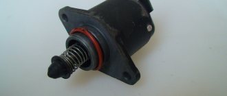
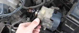
The rotation counting system must be checked one at a time. It’s better to start by checking the ignition coil; it is the one responsible for the operation of this device in the first place.
Coil
This element is an inductor. Its task is to convert electrical voltage into a pulse of a certain magnitude and value. There are 2 contacts on the element.
- Contact "B" is the "+" input from the battery. This contact is the beginning of the primary winding of the inductor.
- Contact “K” is the outlet for the controller.
- The central contact is necessary to supply a spark to the spark plugs.
To check the coil you will need a multimeter. The check is carried out as follows:
- Switch the multimeter to the mode for measuring electrical resistance.
- The red test lead is connected to pin “B”.
- The black test lead is connected to pin "K".
- The resistance of the primary winding should vary between 3–3.5 Ohms.
If lower data is available, the device can be considered faulty. Next, the secondary winding is checked.
- The tester switches to resistance measurement mode.
- The red test probe is connected to contact “B” on the coil.
- The black test lead connects to the center output.
- Operating resistance should be in the range from 5.4 to 9.2 kOhm
Any deviations are considered a malfunction. Next, check for a short circuit:
- The multimeter must be switched to dialing mode.
- The red test lead is connected to pin “B”.
- The black test probe is connected to the device body.
The absence of a signal from the tester will indicate the integrity of the winding, and the absence of a short circuit between contact “B” and the housing. In a similar way, contact “K” and the central output are checked. The absence of a buzzer from the tester will indicate the integrity of all windings. It is also worth visually inspecting the reel for dents and cracks. Any damage may impair the operation of the device.
Voltage check
Voltage plays a big role in the ignition system. To check, start the engine. Next you need:
- Switch the tester to DC voltage measurement mode.
- Connect the red probe to the “+” terminal of the battery.
- Connect the black test probe to the minus terminal.
The generator charging voltage should be between 13 and 15 volts. Next, you need to connect the red tester probe to contact “B” on the ignition coil. The presence of voltage will indicate the integrity of the wiring.
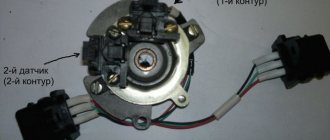
Distributor
Also an important element. The tachometer receives electrical impulses from it. Contactors can be electronic or mechanical. Checking the mechanical device comes down to cleaning the contact itself and setting the gap between the breaker. When the starter is cranked, a spark should appear at the contacts.
The electronic contactor is a Hall sensor. During rotation of the shank, electrical impulses are generated. Checking your device is very simple:
- Connect the red measuring probe of the multimeter to contact “2” of the sensor.
- Connect the black probe of the tester to ground.
- Crank the engine with the starter.
The sensor should produce a voltage of 4 to 15 volts, depending on the crankshaft speed.
Capacitor
This element is responsible for equalizing the voltage in the circuit. It's easy to check. It is enough to turn on the control light in the circuit between the capacitor and the ignition coil.
When the ignition is on, the light should not light up. If this happens, the capacitor will have to be replaced.
Wires
The wires that distribute the spark to the spark plugs are also often the cause of short circuits. They can be checked with a tester. But the problem is that in this way only the integrity of the wire cores is checked.
For penetration with the body, the test can be carried out as follows:
- Start the power unit.
- Open the hood of the car slightly.
- In dim light, it is very easy to see the spark that breaks through the insulation of the wires onto the housing.
All faulty wires must be replaced.
Fuse
On vehicles with a high panel, the tachometer is protected by fuses “F16” and “F15”.
They must be checked for the integrity of the internal jumper. This can be done visually, or using the tester in dialing mode. The fuses are rated 10 amps. Replacement must be carried out strictly with an exact analogue.
Tachometer
To check the tachometer, you need to disconnect its pulse wire from terminal “K” of the ignition coil. Next, use this wire to touch the “+” terminal of the battery several times. The arrow should react with movement when voltage is applied. If this does not happen, then the tachometer receiver is faulty.
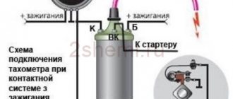
Next, we will describe the connection diagram for the tachometer on a VAZ-2109 with a carburetor fuel injection system.
Connection diagram for tachometer VAZ-2108 and 2109
Let us immediately note that the fuel supply system – injector or carburetor – does not play a special role here. As you know, currently the most common are cars with the following engine types: gasoline or diesel. Depending on this, the tachometer is selected, unless, of course, it comes in the stock version. The thing is that on gasoline engines the tachometer reads data from the ignition coil, or rather, the impulses that arise here. However, the design of diesel power plants does not provide for this unit. Accordingly, here the tachometer reads pulses not from the ignition coil (for lack of one), but from the generator.
The first two wires (12-volt and Signal) are to contacts “B” and “K” of the ignition coil, respectively. All that remains is to secure the mass in any convenient place.
Speed under control
It would seem, why do we need a tachometer? To safely travel around your native expanses, a speedometer is quite enough. If you also look at road signs from time to time, the speedometer will help you save money when meeting with law enforcement officers. The tachometer informs about something almost abstract: how many times the crankshaft manages to turn around in a minute. Why and who needs such information?
First of all, the driver of a car with a forced engine. It requires strict control of revolutions - here all the power is hidden in a narrow range of speeds in each gear, and the tachometer helps determine the moment of transition to the next gear - without dips or twists.
There is also an aesthetic side to the matter. People decorate their car as best they can, and a catchy dial on the dashboard is fashionable. Not everyone thinks about what is hidden behind the instrument readings. Is this why remote tachometers, which are plentiful in stores, are sometimes distinguished by an enviable - up to 25-30% - disregard for the accuracy of readings. We don’t recommend dealing with such people - fortunately, there are honest devices, which we’ll talk about.
In terms of price-quality ratio, the best tachometers are standard ones. Their work is based on different principles.
A mechanical drive - a flexible shaft (cable), the same as in the drive of a simple speedometer, will not be considered here. It is long outdated. Modern tachometers are completely different - both in design and in the way they count revolutions. One of the most common is counting ignition pulses. This device is installed on carburetor cars. It converts the signal frequency into a voltage proportional to it, which moves the needle.
On four-cylinder four-stroke engines, each crankshaft revolution corresponds to two flashes in the cylinders, in other words, two pulses in the ignition circuit. Of course, the tachometer designed for the “four” cannot be thoughtlessly installed on an engine with a different number of cylinders - it would be shameless to lie! On the scale of a foreign tachometer, a number is usually placed indicating the number of cylinders. Domestic ones are designed for four. If you want to bet on Oka, the readings will be half the actual ones.
On diesel cars, the crankshaft rotation speed is estimated by the frequency of the sinusoidal signal from one of the generator phases. Of course, the drive intervenes - the ratio of the diameters of the pulleys, on which the rotation speed of the generator rotor depends. You cannot change the pulleys, but tachometers use a kind of trimmer - a trimming potentiometer. It allows you to regulate the voltage value into which the signal frequency is converted. This makes it possible to carefully adjust the tachometer readings.
A significant advantage of the “generator” tachometer is its versatility. The device can be installed on a gasoline engine with any number of cylinders... or without them at all - even on a gas turbine, as long as the car has a three-phase alternating current generator.
Possible faults
It’s understandable why drivers decide to install the device on cars with low panels, but before you connect the tachometer, you need to understand its main faults.
Symptoms of device failure are:
- when starting the power unit or while driving, the instrument needle may begin to jump;
- When the engine is running, the needle on the scale points to zero.
To begin with, if malfunctions are detected, you should diagnose the wiring and condition of the contacts. If the circuit for connecting the tachometer to the ignition switch was made using silicone wires, this can also lead to incorrect operation of the device. Sometimes the reason for a non-working device lies in a breakdown of the motor speed controller. As for digital devices themselves, in this case the digital display most often breaks down, so in the event of such a breakdown, the display will have to be replaced.
Malfunctions of the injection version
If you have an injection VAZ 2109, the signal to the tachometer comes from the crankshaft position sensor (CPS) through the engine electronic control unit (ECU). The inductive DPKV is located at a distance of 0.8–1.2 millimeters from the gear ring of the generator pulley, and the pulley is mounted on the crankshaft. This pulley has 58 teeth, with two pairs located at twice the distance from each other. It looks like there were 60 teeth at first, but then two were removed. Twice per revolution, when a missing tooth passes the sensor, the DPKV generates a modified signal. Based on the interval between such signals, the ECU calculates the crankshaft rotation speed and uses it both to determine the timing and duration of the injection pulse into the combustion chambers, and to send a signal to the tachometer. Failure of the ECU and DPKV, as a rule, leads to the inability to start the engine.
It’s hard to imagine that the ECU correctly controls the entire operation of the engine, but gives the signal to the tachometer incorrectly. This means that jumps in the readings of the device almost certainly indicate a malfunction or problems with the connection. Most often, the tachometer needle twitches when contact with the ground is broken. The contact may partially come off, slightly oxidize, or become loose in the socket. First of all, you need to check it.
To check the contact you will have to remove the dashboard. On the steering column, under the plastic, a bolt and a socket of contact terminals will open. Inspect the contacts, make sure they fit properly, clean off any traces of corrosion, and spray the contact group with WD-40 spray. Put everything back together. If this does not help, you will have to raise the question of replacing the dashboard.
There is an alternative option - to put up with the jumps, jumps and twitching of the tachometer needle of your VAZ 2109. If you are an experienced driver, then you are quite capable of approximately determining the engine speed by ear. If you don't use your car for work and don't fight for every gram of fuel consumption, then perhaps you should turn a blind eye to the problem. Otherwise, it is better to replace the part.
If you find an error, please select a piece of text and press Ctrl+Enter.
Malfunctions of the carburetor version
An ignition coil is used as a source of information about the speed of rotation of the crankshaft in the VAZ 2109 carburetor. It is designed to generate a spark that ignites the fuel-air mixture in the combustion chambers. Essentially, it is a mini pulse transformer that converts 12V to 30KV. In a four-cylinder engine, a spark is generated twice per revolution of the crankshaft. Taking this circumstance into account, the tachometer determines the number of revolutions per minute and deflects the needle proportionally.
Normal operation of the engine while the tachometer needle of the VAZ 2109 is jumping indicates a failure of the device itself, a wiring fault or problems in the units associated with the ignition coil. Start by checking the wiring. The device removes the signal from the negative coil, switching occurs through the terminal system and the fuse block. If a visual inspection does not reveal a problem, you can connect the coil to the tachometer directly using a meter-long piece of wire. If the problem disappears, you can leave this temporary connection as a permanent one, attaching the wire to the standard harnesses.
Inspect the high-voltage wires, distributor and switch. A very likely cause of the needle jumping is a faulty switch. In the VAZ 2109 this device cannot be repaired and can only be replaced. Experienced motorists carry this inexpensive and easy-to-install spare part with them.
Connect the replacement switch without installing it, and if the arrow stops moving, replace the switch. If all this does not help and the tachometer still does not work, consider replacing the device.
Purpose
The tachometer serves to visually monitor the number of revolutions of the power unit, both at idle and while driving at different speed ranges. It is convenient for the driver to control the number of revolutions when shifting a manual transmission if music is playing or the muffler is damaged. In addition to monitoring speed, using a tachometer it is very easy to adjust the carburetor of the car. A car enthusiast just needs to adjust the carburetor to a tachometer position within 800 rpm.
What is a tachometer and why is it needed?
A tachometer is a device that, as I already said, shows the number of engine revolutions per minute (thousand rpm). The tachometer readings are necessary to make it easier for the driver (usually a beginner) to navigate and correctly select the desired gear (up or down). A tachometer is also necessary in order to monitor the correct operation of the engine by the number of revolutions. For example, when the speed fluctuates or is too high, a fault can be detected in time.
The first tachometers were analog (they are also called dial gauges). Analog tachometers have a dial with numbers and an arrow. One division of the analog tachometer is equal to 1 thousand revolutions. A little later, digital (electronic) tachometers began to appear on mostly Western-made cars. Data in electronic tachometers is displayed on a display (LCD or LCD display). In modern cars, digital tachometers look like analog ones because, like older tachometer models, they display information in the form of a dial and an arrow that indicates the number of revolutions.
October 2009
| Mon | W | Wed | Thu | Fri | Sat | Sun |
| « Sep | But I " | |||||
| 1 | 2 | 3 | 4 | |||
| 5 | 6 | 7 | 8 | 9 | 10 | 11 |
| 12 | 13 | 14 | 15 | 16 | 17 | 18 |
| 19 | 20 | 21 | 22 | 23 | 24 | 25 |
| 26 | 27 | 28 | 29 | 30 | 31 | |
Recently, quite a lot of friends and acquaintances have been changing their carb systems to an injector. In principle, there is quite a lot of information on this matter... But people periodically have some questions... In this article I will tell you how to connect a tachometer and speedometer to an injection car with an old-style instrument panel (not VDO!)
I myself solved this problem simply - I installed a VDO panel. Everything there is simple and clear, and I have enough information on connection on my blog. But as practice shows, sometimes people do not have the opportunity to buy VDO, since the budget is limited... And sometimes, out of ignorance, they prefer not to worry at all and drive without a speedometer and tachometer.
Speedometer As we know, on old-style devices there is no speed sensor, but a speedometer cable. The dashboard also does not have a speedometer signal input, but there is a hole for the speed cable. The problem is easily solved, you just need to buy a suitable speed sensor. According to their design, there are two types. One without cable implementation
install such a sensor on the VDO dash
But such a sensor is installed on the devices with a cable
Those. it is connected to the COURT harness, and the cable is also inserted into its hole. those. the sensor takes data without disturbing the old design.
That's basically all about the speed sensor. The only thing worth considering is that there are different connectors, be guided by the one you need.
Tachometer
They told me that on the instrument panel of a tall torpedo there is a separate input for a low-voltage tachometer - pin 5 of the red block.
The following can only be considered as a theory of converting a high-voltage signal into a low-voltage one
The situation with this issue is even more complicated than with the speed sensor. To be honest, many friends asked “how do we connect the tachometer?” ... I kept silent and said, “I know it’s possible, but how? xs." Again, as for the VDO panel, everything is simple, there are initially two connectors on the white block for connecting the tachometer injection signal (pin 2) and for connecting a high-voltage signal (pin 3). A high-voltage signal is needed when the VDO tidy is installed on a carburetor car. But what if the tidy is old? I thought about this a lot, especially because I have an old instrument panel and tachometer on one injection machine. I was too lazy to look at how everything was implemented... Out of boredom today I started studying electrical circuit diagrams and came to an interesting observation. ’ll just make a reservation right away: I haven’t tested this in practice, so I can’t vouch for it. If someone checks it, please write about your success. While studying the circuit diagram of the VDO instrument panel, I noticed that the only difference in each signal input is that there is a resistor on the high-voltage track. that's all. everything is very simple. I dare to suggest that on the old tidy there is also a resistor on the tachometer track that converts the high-voltage signal into a low-voltage one. Therefore, to connect an injection tachometer to this tidy, you just need to disassemble the tidy, pay attention to the contact path that comes from pin 3 of the red block and find this resistor. Remove the resistor from the device or bypass it. those. solder the bypass wire. Again, I emphasize that these are all just theoretical thoughts, since I myself have not disassembled the device. If anyone does it, be sure to post the results. If someone sends photos of the disassembled device or a report on this operation, I will be grateful.
I checked it with the tachometer. I just connected the device with VP to January 7.2. Everything is a bundle, there are no problems, you don’t need to do anything with the resistor, just stretch the wire from the instrument panel (red connector, 3rd pin, red-brown wire) to the controller wiring (it’s also red-brown there). Everything works great. Thanks for the tip, I thought there was a completely different signal there.)
Reasons for a non-working tachometer
The tachometer in a car is used to indicate the number of revolutions of the engine crankshaft. Let's look at why the tachometer doesn't work and how to find and eliminate the cause of the breakdown. We will definitely dwell on the device and principle of operation, which will help to find out why the tachometer stopped working, the needle twitches or behaves inappropriately.
Classification by operating principle
- Mechanical or electromechanical tachometers with direct drive. The revolutions are transmitted to the dial indicator through a flexible shaft, which, through a worm gear, receives rotation directly from the crankshaft or one of the transmission shafts. The operating principle of the indicator is based on the phenomenon of eddy current induction. The operation and design of a magnetic tachometer are extremely similar to the operating principle of a car speedometer. In modern cars, a similar tachometer design is not used.
- Electric machine. A distinctive feature is the connection to a generator. It is used primarily on diesel engines, but for the purpose of unification, a device of this type can also be used on gasoline engines.
- Electronic. The signal can be taken either from the ignition system or directly from the computer. Installed on gasoline and diesel internal combustion engines.
Design and principle of operation
Main components of electric machine and electronic tachometers:
- measuring unit, or signal converter. It can be based on elements of analog circuitry or built using special microcircuits;
- display unit with analogue or digital display of the number of revolutions;
- auxiliary elements.
The operation of electronic tachometers is based on the conversion of individual signals or pulses captured from the computer, ignition system or generator into a signal “understandable” for the display unit.
Connection diagram
When looking for the reason why the tachometer does not work, it is first of all important to understand the connection diagram and the type of signal. There are 3 typical connection schemes:
- to a contactless ignition system (the tachometer wire is connected to the primary circuit of the ignition coil). The operating principle is based on measuring the frequency of voltage surges in the primary circuit of the ignition system. Calculating the ignition angle is impossible without focusing on the number of crankshaft revolutions, therefore the sparking frequency directly depends on the crankshaft rotation speed. On 4-cylinder internal combustion engines, a full revolution of the crankshaft corresponds to 2 voltage pulses in the primary circuit. Accordingly, the higher the crankshaft rotation speed, the greater the frequency of voltage surges;
- connection to the contact ignition system. The operating principle and connection diagram are similar to the BSZ, but the design of the measuring unit will differ depending on the voltage of the input circuit;
- connection to the engine ECU. The principle of operation is still based on recording voltage pulses in the primary circuit of the ignition system, but the signal to the tachometer comes from the engine control unit;
- connection to the generator (the tachometer signal contact is connected to terminal W of the generator). The rotation of the generator pulley is carried out by a belt drive from the crankshaft, so the rotation speed of the generator rotor will always be proportional to the crankshaft speed. The change in the number of revolutions of the crankshaft can be calculated by constantly measuring the amount of EMF generated on the winding. According to its principle of operation, an electric machine tachometer resembles a regular one class=”aligncenter” width=”448″ height=”412″[/img]
Typical faults
If the mechanical tachometer on a car stops working, there is mechanical damage to any of the structural elements. A broken cable of a flexible shaft, wear of the worm gear elements, the appearance of backlashes, deformations - all these reasons can cause the engine speed indicator to fail.
What to pay attention to if the electronic tachometer does not work:
- integrity of electrical wiring. In this case, it is important to check not only the signal wire, but also the ground and power supply of the instrument panel;
- quality of contacts. The presence of oxides and loose contact inside the chips may well cause the tachometer to fail;
- the integrity of the elements of the measuring unit, which are located behind the protective glass inside the dashboard. Among mechanical damage to transistors, burnout of microcircuits, tracks or swelling of resistors, the most common reason for a non-working tachometer is a violation of solder integrity. For example, on the Mitsubishi Padjero II, the appearance of microcracks in the soldering areas of the tachometer elements is a generally recognized disease.
On vehicles with an alternator connection, a non-functioning tachometer may indicate a faulty alternator. In this case, the breakdown is accompanied by the lighting of the low battery charge indicator and the sporadic lighting of a “garland” of warning lights on the dashboard.
In some types of design, changes in the linear resistance of high-voltage wires can make adjustments to the accuracy of the engine speed indication.
How to find the cause of the problem yourself
In addition to a visual inspection, for DIY diagnostics you will need a universal measuring device. If you know how to use a multimeter, you can easily check the power supply, ground, and also test the signal wire for a break.
The power supply is checked in DC measurement mode, the measurement range is up to 20 V. “Minus” is constant, “plus” appears only after the ignition is turned on. Pulses on the signal wire should appear when the crankshaft rotates. To search for a break, the multimeter must be switched to resistance measurement mode - ohmmeter. Sometimes, to detect a bad contact, it is enough to move the connector or harness in which the signal wire of the speed indicator is laid.
Tachometer needle twitches
The problem of a twitching needle is best known to owners of the GAZ 3110 Volga.
The problem occurs on cars manufactured before September 1999 and equipped with instrument cluster 38.3801 (JSC Avtopribor). Due to design defects, the natural operation of a car generator, in which the amount of charging current is regulated by an alternating voltage supply to the excitation winding, leads to the twitching of the needle. The tachometer needle may twitch due to weakened tension of the alternator belt, but in most cases it is possible to repair the tachometer on the Volga by replacing the dashboard and modifying the connection diagram.
vote
Article rating
Idle speed adjustment
The second setting of the VAZ-2109 carburetor is idle speed, it can be partial or full. The first is for minor speed adjustments, the second is for adjusting the amount of air (setting CO emissions in the exhaust gases).
Partial adjustment is performed using the air-fuel mixture “amount” screw. This screw sets the opening angle of the throttle valves, which ensures that the air-fuel mixture enters the cylinders when the accelerator pedal is released. The “quantity” screw rests on the throttle valve control lever and when screwed in, it pushes the lever, causing the valves to open slightly.
Partial idle adjustment is performed with a warm engine and creating a load on the vehicle's on-board network by turning on the high beam headlights and the interior heater at full power. The adjustment is carried out with the engine running by screwing in/unscrewing the “quantity” screw until the optimal idle speed is established, which for the VAZ-2109 is 800-900 rpm (this can be tracked using a standard or plug-in tachometer).
If it is not possible to set the required speed or the motor operates unstably at it, a complete adjustment is made, which is made by two screws - “quantity” and “quality”.
The algorithm for this adjustment consists of the following stages:
- Warm up the engine and then turn it off;
- We find the quality screw (it may be closed with a plug that will have to be removed), screw it in until it stops, and then unscrew it 3-4 full turns;
- We start the engine, turn on electrical consumers (lighting and stove) to create a load in the on-board network;
- By rotating the “quantity” screw, we achieve 700-800 rpm on the tachometer;
- By turning the “quality” screw, we set the maximum possible speed (they will increase to a certain level, and then stop. The moment the speed increase stops is considered the maximum);
- We set the “quantity” screw to 900 rpm;
- Using the “quality” screw we lower them to 800 rpm;
- We slowly tighten the “quality” screw until interruptions appear in the operation of the power plant, after which we unscrew it back 1 turn;
- We adjust the speed with the “quantity” screw, bringing it to a normal value - 800-900 rpm;
After the adjustment operations, we check that they were carried out correctly. This is done by sharply pressing the gas pedal and then quickly releasing it. With a properly configured carburetor, the engine should respond quickly to pressure, without any failures or hesitations. And after releasing the pedal, the speed will drop to the idle level, without sags or instability of the engine.
Connection
Connecting the tachometer of a VAZ-2109 car can be done regardless of the model of this car. The connection will be identical for a car with a high and low panel. The connection process is as follows:
- Place 3 wires with a cross-section of at least 2 square meters into the engine compartment. mm. It is better that these are not separate wires, but a solid cable. You must first attach round terminals to all 6 ends.
- Place the cable or wires into the hole intended for the flexible speedometer shaft (cable). It is necessary to insert a rigid steel wire into the hole, attach the prepared cable to it and pull it under the hood.
- The tachometer has only 3 contacts: “+”, “minus”, “W”, you need to connect the ends of the prepared wires to them.
It is better to choose 3 wires of different colors, this will make it easier to connect their ends under the hood.
In the engine compartment, the connection is made as follows:
- The wire from the “+” contact of the tachometer is connected to contact “B” of the ignition coil.
- The wire from the “W” terminal is a pulse wire and is connected to the “K” terminal of the coil.
- The minus wire must be connected to a previously prepared place. It is better to first clean this place from dirt, oil and paint. The best connection to ground is established using a bolt. Alternatively, this wire can be connected under the coil mount.
- Next you need to test the device. To do this, the power unit needs to be started and warmed up at low speeds. If the carburetor is configured correctly, then the needle should be at 800 rpm. When you press the gas pedal, the arrow should deflect. The pointer should not jump, get stuck in place, or slowly return to minimum values when the gas is suddenly released.
If the device was connected for a car with a low panel, then you need to install the tachometer in any convenient place. For such cars, you can install an electronic and mechanical engine speed counter. Before purchasing, you need to make sure that the tachometer is suitable for working with a 4-cylinder power unit. The electronic device must be selected of a simple type, which is not intended to interact with the on-board computer, since this car model simply does not have one.
This diagram does not provide for connecting the tachometer through the fuse block. On a standard circuit for cars with a high panel, the “+” contact of the tachometer should be connected to the output of fuse “F16”. Pulse contact "W" is connected to fuse "F15".
If the installation is carried out for a car with an unspecified tachometer, then the “+” contact can be connected to the interior lighting fuse. This protection circuit has the least load. For contact “W” you will have to solder an additional contactor to turn on the fuse, or use the free space on the block. A fuse is especially necessary for the impulse wire. Any minor voltage surges can damage the device's pulse receiver.
Installation
That’s it, the tachometer is in your hands, so you can safely take it to your own garage and start connecting the device.
There is no need to be afraid of self-installation. Although the tachometer is an electrical device, it consists of three wires. Therefore, even inexperienced drivers will be able to cope with the task without any problems.
Wiring is no problem
Decide in advance on the location where your crankshaft speed reading device will be located. Here the choice is entirely yours. Some are installed directly on the instrument panel, others are mounted near the ignition switch. Try to choose an area where the device will not interfere and will not spoil the appearance of the interior.
Why does the VAZ tachometer jump?
It often happens that the needle starts to twitch. If the car is fuel-injected, then troubleshooting involves connecting a diagnostic scanner and checking the engine systems. Jumps in the TX-193 needle in most cases are also a symptom of malfunctions associated with its electrical circuit. The reasons for this behavior of the device may be:
- lack of good contact at the negative terminal of the battery;
- oxidation or burning of the brown wire on the ignition coil;
- burning or wear of the contacts of the ignition distributor cap or slider;
- wear of the distributor shaft bearing;
- shorting the red wire powering the device to vehicle ground;
- malfunction of the crankshaft position sensor (for injection engines).
A similar problem is solved by stripping the contacts, replacing the ignition distributor cap, slider, support bearing, restoring the integrity of the insulation of the device’s supply wire, and replacing the crankshaft sensor.
Another jump may be due to the inoperability of the capacitor located at the bottom of the breaker. The capacitor may be broken or its contact is very weak.