The “sevens”, like most modern cars, use a single-wire circuit for supplying electricity to electrical equipment. The other terminal of the consumer is always connected to the ground of the machine to which the negative terminal of the battery is connected. This solution allows not only to simplify the design of the on-board network, but also to slow down corrosion.
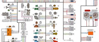
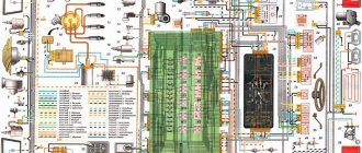
VAZ-2107 diagram: first option
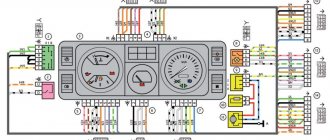
Full size wiring diagram:
Electrical diagram VAZ-2107 carburetor
Electrical diagram of VAZ 2107, 21074 produced in 1988-2001 with generator 37.3701
- block headlights
- side direction indicators
- accumulator battery
- starter relay
- carburetor electro-pneumatic valve
- carburetor microswitch
- generator 37.3701
- gearmotors for headlight cleaners *
- Fan motor switch sensor
- engine cooling fan motor
- sound signals
- distributor
- spark plug
- starter
- coolant temperature gauge sensor
- engine compartment lamp
- low oil pressure warning sensor
- low brake fluid level indicator sensor
- windshield wiper motor
- carburetor electro-pneumatic valve control unit
- ignition coil
- headlight washer pump motor *
- windshield washer pump motor
- mounting block
- windshield wiper relay
- hazard warning and direction indicator relay
- brake light switch
- reverse light switch
- ignition relay
- ignition switch
- three lever switch
- hazard switch
- socket for portable lamp**
- heater fan switch
- additional resistor for the electric motor of the heater (stove)
- rear window heating indicator lamp
- low brake fluid level warning lamp
- signaling unit
- heater fan electric motor
- glove compartment lamp
- light switches on the front door pillars
- switches for warning lights of open front doors ***
- front door open warning lights ***
- connection block
- cigarette lighter
- watch
- instrument light switch
- diode for checking the serviceability of the low brake fluid level indicator lamp
- fuel level indicator
- fuel reserve indicator lamp
- speedometer
- turn signal indicator lamp
- carburetor choke indicator lamp
- battery charge indicator lamp
- carburetor choke warning switch
- instrument cluster
- econometrician
- light switches on the rear door pillars
- coolant temperature gauge
- tachometer
- indicator lamp for parking brake activation (“handbrake”)
- low oil pressure warning lamp
- high beam indicator lamp
- indicator lamp for turning on external lighting
- voltmeter
- Parking brake indicator switch (“handbrake”)
- outdoor light switch
- rear window heating switch with backlight
- rear fog light switch with on/off indicator *
- fog light circuit fuse
- lampshade ****
- tail lights
- level indicator and fuel reserve sensor
- connectors for connecting to the rear window heating element *
- license plate lights 2107
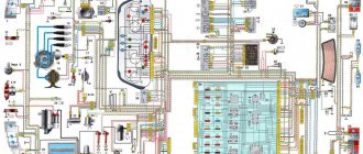
Wiring diagram VAZ-2107 carburetor - full view:
Electrical circuits for VAZ 2107 cars with injection and carburetor engines
The electrical wiring of all versions of the VAZ 2107 is the same, with the exception of the engine compartment wires. The electrical network is built according to a single-wire circuit, the second conductor is the car body and the crankcases of the units. When using VAZ 2107 electrical circuits, you should take into account the likelihood of a restoration repair being carried out on a particular vehicle, since sections of the wiring may have been replaced.
Mounting block connection diagram
P1 — relay for turning on the heated rear window; P2 - relay for turning on the headlight cleaners and washer; P3 - relay for turning on sound signals; P4 - relay for switching on the electric motor of the engine cooling system fan; P5 - headlight high beam relay; P6 - low beam headlight relay; A - the order of conditional numbering of plugs in the mounting block blocks. The outer number with the letter “Ш” in the plug designation is the block number, and the inner number is the conventional number of the plug.
Schemes of individual blocks of the seven
Power supply system
Power plant starting system
1 - starter; 2 - relay; 3 — ignition switch; 4 - battery
Ignition system
1 - generator; 2 — ignition switch; 3 - distributor; 4 - breaker; 5 — candles; 6 - coil; 7 - battery
Contactless ignition system
External and internal lighting
Windshield wipers and washers
1 — electric motors of the windshield wiper; 2 — washer motor; 3 — mounting block; 4 — ignition switch; 5 - washer switch
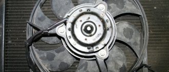
Cooling Fan
1 — fan electric motor; 2 - sensor; 3 — mounting block; 4 - ignition relay; 5 - ignition switch.
Distributor
The ignition distributor (distributor) is designed to transmit high-voltage current pulses that come from the coil to the spark plugs. The distributor consists of:
- aluminum body;
- shaft;
- Hall sensor;
- vacuum and centrifugal ignition timing regulators;
- runner;
- covers with four fixed contacts.
In “sevens” with contactless ignition, distributors of type 38.3706 are used.
A Hall sensor is installed on the distributor 38.3706
Table: technical characteristics of distributor type 38.3706
| Characteristics | Indicators |
| Supply voltage, V | 12 |
| Permissible speed, rpm | 3500 |
| Switching on the centrifugal regulator at, rpm | 400 |
| Maximum angle of the centrifugal regulator, o | 15,5 |
| Turn on the vacuum regulator at, mm. Hg Art. | 85 |
| Maximum angle of the vacuum regulator, o | 6 |
| Operating temperature range, oС | -40 — +100 |
| Weight, kg | 1,05 |
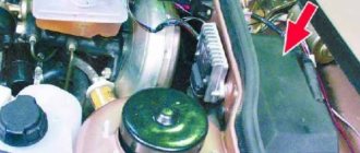
Where is the distributor located in the VAZ 2107
The ignition distributor is mounted on the left side of the engine cylinder block. Its shaft is driven by the auxiliary drive gear. The number of revolutions of the distributor shaft directly depends on the speed of rotation of the crankshaft.
The distributor is located on the left side of the cylinder block
Malfunctions of the VAZ 2107 distributor and their symptoms
The most common breakdowns of the “seven” distributor include:
- burning of the fixed contacts of the cover;
- mechanical damage or electrical breakdown of the cover;
- burning of the runner.
As for the symptoms, for the listed problems they will be similar:
- unstable engine operation;
- reduction in power characteristics of the power plant;
- increased fuel consumption.
To diagnose major damage to the distributor, it does not need to be removed from the engine . It is enough to disconnect the high-voltage wires from the cover and unfasten the two latches that secure it to the body. By removing the cover and inspecting the contacts with the slider, you can visually assess their condition and draw a conclusion about how suitable they are for further work. If the contacts cannot be cleaned, the device cover must be replaced. Such a part costs about 200 rubles. The runner will cost half as much.
The distributor cover is attached to its body using two latches
Wires for connecting electrical appliances
| Connection type | Section, mm2 | Insulation color |
| Negative terminal of the battery - vehicle ground (body, engine) | 16 | Black |
| Starter positive terminal - battery | 16 | Red |
| Positive contact of the generator - plus battery | 6 | Black |
| Generator - black connector | 6 | Black |
| Terminal on the generator “30” – white MB block | 4 | Pink |
| Starter connector “50” – starter relay | 4 | Red |
| Starter Start Relay - Black Connector | 4 | Brown |
| Ignition switch relay - black connector | 4 | Blue |
| Ignition switch output “50” – blue connector | 4 | Red |
| Ignition switch connector “30” – green connector | 4 | Pink |
| Right headlight plug - ground | 2,5 | Black |
| Left headlight plug - blue connector | 2,5 | Green, gray |
| Generator output “15” – yellow connector | 2,5 | Orange |
| Right headlight connector - ground | 2,5 | Black |
| Left headlight connector - white connector | 2,5 | Green |
| Radiator fan - ground | 2,5 | Black |
| Radiator Fan - Red Connector | 2,5 | Blue |
| Ignition switch output “30/1” – ignition switch relay | 2,5 | Brown |
| Ignition switch contact “15” – single-pin connector | 2,5 | Blue |
| Right headlight - black connector | 2,5 | Grey |
| Ignition switch connector “INT” – black connector | 2,5 | Black |
| Six-pin block of the steering column switch - “ground” | 2,5 | Black |
| Two-pin block of the steering column switch - glove box illumination lamp | 1,5 | Black |
| Glove compartment light - cigarette lighter | 1,5 | Black |
| Cigarette lighter - blue block connector | 1,5 | Blue, red |
| Rear window defroster - white connector | 1,5 | Grey |
Useful: Lada Vesta VAZ-2180 diagram
Failure of the main vehicle systems
The reason for the sudden failure of many components of the VAZ 2107 car may be damage and failure of electrical wiring elements.
The most common wiring failures are listed below:
- A common defect is a blown fuse link caused by a circuit overload or short circuit. Since the electrical circuit of the VAZ 2107 often uses old-style fuses, oxidation or loosening of the contact clamps in the mounting block often occurs. To correct these faults, replace the fuse or clean the contacts. The latest car releases used mounting blocks with blade fuses, which provide better contact and more reliable operation of the electrical circuit.
- A more complex case is the burning or oxidation of conductive tracks in the mounting block. To repair, the unit is removed from the car, the damaged areas are soldered and covered with protective varnish. In case of critical damage, the unit must be replaced.
- When a section of the wiring is short-circuited, the fuse-link will constantly burn out. To find a damaged element, you need to test the circuit with a multimeter. Replaced wires should be carefully laid along the standard route. An open circuit is also determined by the continuity of the wires.
- If there is a problem with the components of the injection system, the Check Engine indicator light on the instrument cluster may turn on. The cause may be sensor failure or broken circuits. To find the causes of damage, you should diagnose the injection system using a test device connected to the diagnostic connector. The error codes available in the system can be deciphered and repairs are made based on this data.
- The cause of complete inoperability of the electrical system may be a discharged battery or oxidation of the negative wire that is connected to the body. A low battery is indicated by a dim glow of the control lamps and their complete shutdown when a load is connected (horn or an attempt to crank the engine with the starter).
- A burning battery charging lamp with the engine running indicates a malfunction of the generator or an open circuit connecting the generator to the battery.
- Light pulsations when the engine is running are a symptom of a burnt-out control relay on the generator. The relay must be replaced, since operating the vehicle with increased voltage in the on-board network is unacceptable.
The video provided by the Avtoelektrika HF channel shows the repair of the wiring of the reversing lights on a VAZ 2107.
Car wiring diagram
1 – radiator fan drive motor; 2 – relay and fuse block (mounting block); idle speed sensor; 4 – engine control unit; 5 – potentiometer; 6 – set of spark plugs; 7 – ignition control unit; 8 – electronic crankshaft sensor; 9 – electric fuel pump; 10 – tachometer 2107; 11 – lamp for monitoring the health of electronic systems; 12 – ignition system control relay; 13 – speed sensor; 14 – diagnostic connector; 15 – set of injectors; 16 – adsorber solenoid valve; 17, 18, 19 – fuse block protecting the injection system circuits; 21 – electronic fuel pump control relay; 22 – electronic relay for controlling the intake pipe heating system; 23 – intake pipe heating system; 24 – fuse protecting the heater circuit; 25 – electronic oxygen level sensor; 26 – cooling system temperature control sensor; 27 – electronic air damper sensor; 28 – air temperature sensor; 29 – pressure control sensor.
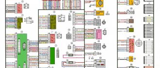
VAZ 21074 engine control system diagram
Wiring diagram of electrical connections of ECM VAZ 21074 - circuit elements. 1 — controller connector; 2 — mass air flow sensor; 3 — coolant temperature sensor; 4 — crankshaft position sensor; 5 — throttle position sensor; 6 — oxygen concentration sensor; 7 — speed sensor; 8 — ignition module; 9 — solenoid valve for purge of the adsorber; 10 — electric fan relay; 11 — electric fuel pump relay; 12 - main relay; 13 - fuse for the power circuit of the electric fuel pump relay: 14 - fuse for the power circuit of the main relay; 15 — fuse-link; 16-fuse protecting the constant power supply circuit of the controller; 17 - diode; 18 — idle speed regulator; 19 — nozzles; X1 - diagnostic block; X2 - connection block to the vehicle electrical system.
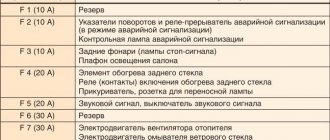
Fuse and relay diagram 2107
On newer “sevens” a block with 17 fuses and 6 relays is installed. VAZ 2107 fuses on the “new” unit protect the following electrical circuits and devices:
- Reversing lamps, heater fan, rear window defroster warning lamp and relay, rear wiper motor and rear washer pump.
- Electric motor for front wipers.
- Reserve socket.
- Reserve socket.
- Power supply for heated rear window.
- Clock, cigarette lighter, power socket “carrying”.
- Signal and radiator fan.
- Turn signal lamps in emergency mode.
- “Fog lights” and a relay that regulates the voltage of the on-board network.
- Instrument panel lamps.
- Brake light bulbs.
- Right high beam headlight.
- Left high beam headlight, high beam warning lamp.
- Side lights (rear right, front left), license plate and engine compartment lighting.
- Side lights (rear left, front right), glove compartment and cigarette lighter lamps.
- Low beam (right lamp).
- Low beam (left lamp).
The block relays perform the following functions:
- Heated rear window relay.
- Headlight cleaner and washer relay.
- Signal relay.
- Cooling system electric fan relay.
- High beam relay.
- Low beam relay.
The fuse block of the VAZ 2107 (injector) is no different from the block on the carburetor “seven”. Injection models are simply equipped with an additional relay and fuse box installed in the cabin under the glove compartment. The block includes three relays - the “main” relay, the fuel pump relay and the fan relay.
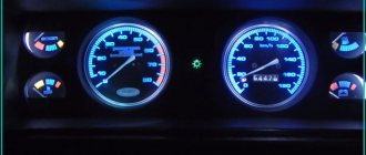
The instrument panel of the VAZ 2107 does not work
Hello everyone, today I would like to look at the main reasons why the instruments on a VAZ 2107 do not work. You will probably agree that when the instrument cluster does not work, some kind of discomfort is created and the driver does not feel very comfortable.
Moreover, the instrument cluster of the VAZ 2107 car provides a lot of important information that is needed both when starting the car and when driving. Well, let's move on to the most important thing, namely, finding the reasons for the failure of the instrument panel.
So, the first thing you need to do is check the fuse that controls the tidy. On the VAZ 2107 this is fuse F10 (10A) which is located in the mounting block. If necessary, this fuse must be replaced.
If you checked the fuse and it is ok, then the problem is in the instrument panel itself. First you need to remove the instrument cluster and check the two black wires that are attached to the car body.
As you may have guessed, this is a mass; you need to check whether the contact is seated well and how well the fastening nut is tightened. You also need to check the contact blocks.
The most common reason why the instrument panel does not work is the pins, which are attached with rivets, and such a connection is not very reliable and due to vibrations and other shaking, the contact disappears, and the instrument panel of the VAZ 2107 car stops working or works intermittently.
This is especially noticeable at sub-zero temperatures while the seven-cold panel in the cabin does not work, and after warming up, when the metal expands a little, the contacts are restored again and the tidy starts working again.
But as you understand, this is not an option to drive like this. In order to fix this, you need to remove the aluminum rivets that hold the board and get to the connectors of the pads.
Then, using a soldering iron, you can restore the contacts. And after that, you can forget about the disease of the instrument cluster of the VAZ 2107. And yes, by the way, instead of the rivets that were drilled out, you can screw in self-tapping screws. Well, that's all for this, if you had other reasons, then write in the comments. Bye everyone.
Modifications of the VAZ-2107 car
VAZ-2107 . Basic version of the sedan, with an 8-valve carburetor VAZ-2103 engine, 1.5 liters.
VAZ-2107-20 . The same VAZ-2107, but with a 1.5-liter VAZ-2104 injection engine that meets the Euro-2 environmental standard.
VAZ-2107-71 . The car for the Chinese market was equipped with a VAZ-21034 engine, with a volume of 1.4 liters and a power of 66 horsepower, specially tuned for A-76 gasoline. The pistons were taken from a VAZ-2108.
VAZ-21070 . Modification of a car with an 8-valve, carburetor VAZ-2103 engine, volume 1.5 liters.
VAZ-21072 . Modification with an 8-valve carburetor VAZ-2105 engine, volume 1.3 liters.
VAZ-21073 . An export modification for the European market, which was equipped with a 1.7-liter injection engine with a capacity of 84 horsepower. The engine of this car had a catalytic converter that satisfied environmental protection requirements.
VAZ-21074 . Modification with an 8-valve, carburetor VAZ-2106 engine, volume 1.6 liters.
VAZ-21074-20 . Modification with a 1.6-liter VAZ-21067-10 injection engine, which complies with the Euro-2 environmental standard
VAZ-21074-30 . Like the previous model, but with a VAZ-21067-20 engine, which meets the Euro-3 environmental standard
VAZ-210740 . Modification produced in 2010, equipped with a VAZ-21067 injection engine with a catalyst. Engine capacity is 1.6 liters, power is 72.7 horsepower.
VAZ-21076 . Export modification with a VAZ-2103 carburetor engine.
VAZ-21077 . Export modification with right-hand drive for the UK market. The car was equipped with a VAZ-2105 carburetor engine with a volume of 1.3 liters.
VAZ-21078 . Another export modification for the UK, but with a 1.6-liter VAZ-2106 carburetor engine
VAZ-121079 . The modification, developed specifically for the needs of the Ministry of Internal Affairs and the KGB, was equipped with a powerful VAZ-413 rotary piston engine with a volume of 1.3 liters and a power of 140 horsepower.
VAZ-2107 ZNG . The car is equipped with an 8-valve, fuel-injected VAZ-21213 engine with a volume of 1.7 liters.
Differences in work
Advantages
So, what are the benefits received by the car owner whose car has injection installed:
- There is less chance of stalling when starting from a standstill - the electronics react more flexibly to the operation of the gas pedal, allowing you to move off more confidently from idle;
The engine compartment wiring harness of the VAZ 2107-20 has different connectors
- Easy engine starting - there is no need to manually operate the choke knob;
- Reduced warm-up time for a cold engine - the electronic system optimizes the minimum stable speed. You can start moving after starting, without fear of jerks and dips typical of a carburetor;
- Reduce routine maintenance of electrical equipment . In particular, there is no need to constantly adjust the gap in the breaker contacts;
For reference: Other domestic car factories also modernized electrical equipment, in particular the ignition system - see the publication on the UAZ 31514 wiring diagram.
- Reduced adjustment work on the carburetor - electronics can reduce fuel consumption and make engine operation more environmentally friendly.
In the video you can see the stable start of the VAZ 2107 injection engine.
Flaws
The injection system also has some flaws, in particular:
- Without a diagnostic tool, it is quite difficult to identify a malfunction in the engine management system;
- Standard wiring 2107 does not allow troubleshooting using a warning lamp;
- The factory instructions most often instruct you to contact a service center for diagnostics. However, the price of such a service is not always justified for the car owner.
In the photo - diagnostics of the oxygen sensor of the VAZ 2107
Although the installation of injection on the “seven” helped the model survive on the assembly line until 2012, nevertheless, modern trends forced AvtoVAZ to stop producing rear-engine versions. We hope that this article, as well as high-resolution electrical and wiring diagrams, will be useful for car owners of VAZ 2107s that remain in service.