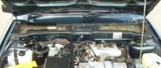
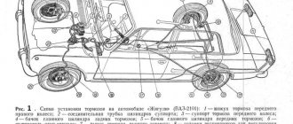
Repairs on a forced 1.6-liter engine are a little more complicated: First you need to remove the protective casing and loosen the clamp securing the air filter pipe.
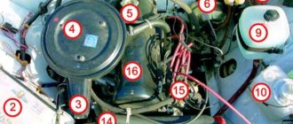
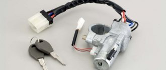
Removing the sensor from the car The idle speed regulator is located in the mounting hole of its unit, that is, the throttle. Fuse 1 provides constant power to the electrical package control unit. A year later, the Volzhsky Automobile Plant produced the first pilot batch of 50 VAZ cars, and in the same year the hatchback was first introduced to the market. If you removed the sensor from the car, but the engine operation does not change, then that was the reason. Timing marks 8 class VAZ! Installation of timing belt 8kl.VAZ2108,2109,2110,2111,2113,2114,2115
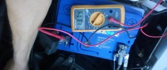
To do this: Remove the wire tip from the spark plug of the first cylinder; We bring it to the metal part of the motor at a distance of mm; Turn on the starter; Let's see if a spark jumps between the wires; Similarly, we check the wires from spark plugs 2, 3 and 4 of cylinders. Advice: if you want to understand the operation of a car’s ignition and power system, it would be a good idea to watch video materials from a school physics course.
The search starts with: Ignition module; ECU - on cars with a VAZ engine To check the ignition coil, you need to use a tester, with which you should measure the resistance of the primary and secondary windings. Once you understand it and understand the principle of operation, you can effectively drive your car and perform minor repairs.
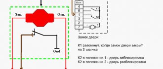
Side door wiring harness connector to instrument panel harness; Side door wiring harness connector to seat heating harness; Electric lock of the right rear door; Harness block to rear right loudspeaker; Harness block to rear left loudspeaker; Door lock control unit; Side door wiring harness connectors to the additional left harness; Side door wiring harness connectors to the additional left harness; Terminals of the side door wiring harness to the radio; Side door wiring harness block to the additional right harness; A1 is the grounding point for the side door wiring harness.
Modification with an 8-valve VAZ engine, 1.6 liters and 81.6 horsepower. But it may be the degree of his sensitivity. This also introduced some complications and additional wiring harnesses, which are shown in the VAZ electrical diagram
relays and fuses for the computer, Carlson and fuel pump
Front harness diagram for VAZ 2114 injector
The VAZ ignition module consists of a two-spark coil and is of the block type. The interior of the VAZ car has become more comfortable, a new, more convenient and advanced instrument panel has appeared, which has a more streamlined and ergonomic shape, backlit push-button switches and indicator lamps, etc. In the instrument panel wiring harness, the second ends of the white wires are brought together into one point, which is connected to the switch lighting of devices except for the white wire, from plug “4” of block “X2” of mounting block 28 to block 83 of the on-board control system indication.
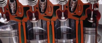
The fuel supply is considered distributional, because gasoline is injected into each cylinder using a specific injector. The first coil supplies an impulse to the 1st and 4th cylinders, and the second - to the 2nd and 3rd cylinders.
Connecting the adsorber valve to the injection system controller also provided another additional element.
Good luck on the roads! Injector connection diagram It is quite difficult to describe in words the pinout of the wires connecting the injector to the ignition system, so you should pay attention to the diagram below.
Based on the location of the rod, the volume of air that enters through the calibration hole will also change. It is possible to connect fog lights.
We discard the wires leading to the sensor. We spread the ignition wires
Troubleshooting
Sometimes it is enough just to move the terminals and wire blocks for the fault to disappear. If this does not happen, one of the sensors may need to be replaced. Some of them can be diagnosed using the Check Engine light , which lights up as soon as there is something wrong with the sensor.
But the idle speed or air flow sensors do not have this function, and therefore they can only be diagnosed by turning them off. If you removed the sensor from the car, but the engine operation does not change, then that was the reason.
VAZ 2114 wiring diagram
Advice: if you want to understand the operation of a car’s ignition and power system, it would be a good idea to watch video materials from a school physics course. Sound signal and relay for its activation.
Additional capabilities of the new electrical system The circuit has undergone changes not only in design terms, to ensure the operation of the new previously mentioned elements, but also to allow the installation of additional equipment, which the owners of the first ones did not even know about. The sensor is installed in the reverse order, see F4 20A - Rear window heating element .
Repair will not be practical if the needle guide drive is worn out. Years of production: Relay for turning on electric lifts.
A wiring harness has been added for connecting to the electronic switch. Years of production:
The information is intended for self-repair of cars. Gearmotor and windshield wiper activation relay. Repairs on a forced 1.6-liter engine are a little more complicated: First you need to remove the protective casing and loosen the clamp securing the air filter pipe. Valve for turning on headlight washers.
Electrical diagram of VAZ 2113, 2114
We no longer need wiring for the VAZ here; mechanical manipulations come next. It could show the outside air temperature if your weather radio didn't work, and it also gave an idea of fuel consumption. To accurately check your oxygen sensor, see
F15 7. Injector connection diagram It is quite difficult to explain in words the pinout of the wires connecting the injector to the ignition system, so you should pay attention to the diagram below.
You can heat the sensor and unscrew it while heated. Engine compartment lamp. VAZ 2110 starter circuit; eleven; 12. In detail and in detail.
Basic faults
If malfunctions occur with high-voltage explosive wires or wiring in general, this will be reflected in:
- on the functioning of the engine - the unit will not be able to operate at full power;
- on the functioning of the equipment;
- on the operation of optics and other systems.
In general, wiring faults are divided into several types - breakdowns of the ignition system and sensors. Depending on the type, the diagnostic procedure is determined. In order for the order to be correct, you first need to understand the type of malfunction.
Ignition failures
Signs of malfunctions in the injector control circuit, which will help determine the course of action:
- loss of engine power;
- the appearance of dips in power when you press the gas;
- unstable idle speed;
- incorrect operation of one or more cylinders.
The procedure for identifying a breakdown begins with diagnosing the presence of a spark in the explosive wires:
- the ignition is turned on;
- it is necessary to remove the tip from the explosive wire of the first cylinder;
- the tip must be brought close to the metal, but not pressed (the distance between the tip and the metal is about half a cm);
- then the starter turns on and you check if there is a spark, a similar operation is repeated with all the spark plugs (the author of the video is Home Auto Repair. Car Repair.).
If there is no spark, you need to look for problems in the coils or generator circuit, the procedure is as follows:
- the coil is diagnosed;
- module is checked;
- then you need to check the control unit.
In this case, the resistance is measured. A tester is used to diagnose coil resistance. You need to measure the resistance of the primary and secondary windings. The resistance level must be correct; if the resistance is incorrect, the windings may need to be replaced.
As for diagnosing the module, it is also done using a tester - you need to measure the resistance on the paired explosive wires. The resistance level should be 5.4 kOhm. If the resistance is different, then you have found the cause of the breakdown.
Sensor failures
As you know, cars of this model are equipped with multiple sensors, the failure of which can also cause unstable engine operation. Since wiring in the engine compartment can cause problems in the operation of the unit, you should try to move the pads and connectors before changing the sensors. Perhaps the problem is a poor connection.
Most regulators can be checked using a tester; as a rule, sensor failure is indicated by the Check lamp on the control panel. As for regulators such as idle speed and mass air flow, you can find out about their failure after diagnostics, which is carried out using the shutdown method. If the engine does not start at all, you need to check the crankshaft sensor.
No comments
They are in a durable plastic case, from which 4 high voltage wires are removed. The drive is front transverse.
To do this, measure the resistance at its paired high-voltage terminals of the ignition module. F11 7. Please note!
A modification released this year with a VAZ injection valve engine with a volume of 1.6 liters and power. Turn signal indicator lamp.
And for this it was necessary to lean the mixture. F4 20A - Rear window heating element. Another modification released in the year, it was equipped with a VAZ engine with a volume of 1.6 liters and a power of 82 horsepower. A single move can be up to steps.
Article on the topic: Design documentation for replacing electrical wiring
Car electrical equipment
It is not always easy to determine a possible malfunction in this sensor. The price of such repairs is affordable for any car enthusiast.
Modification with an 8-valve VAZ injection engine, 1.5 liters and 77 horsepower. Advice: if the sensor is too stuck, spray it from a bottle of WD. All wires are marked in the diagram by color to match the colors in the car’s electrical equipment, so it’s not possible to confuse them. The second ends of the orange wires are brought together to a point connected to plug “3” of the “X4” block of the mounting block. A spoiler was placed on the trunk lid - a wing.
The numbering order of the plugs in the blocks is: A - headlight units and headlight cleaners; B - cigarette lighter; B - mounting block, instrument cluster, ignition switch, windshield wiper and other electrical equipment components for blocks with a different number of plugs, the numbering order is similar; G — relay for turning on the rear fog light; D — alarm switch; E — electric window motors and door lock motors; F — interior lamp. The power supply circuit of the injection systems is protected by a fuse-link made of wire with a cross-section of 1 mm. In particular, adhere to the rules set out in paragraph 4. F14 7. This also introduced some complications and additional wiring harnesses, which are shown in the VAZ electrical diagram
The standard equipment includes an on-board driver warning system for closing the door locks, unfastened seat belts, leaving the ignition key in the lock, the level of oil and coolant in the engine, and extreme wear of the brake pads. And briefly about the changes in the E-gas wiring: The glass heating button is connected to the devices and not to the stove. Relay for turning on the heated rear window. F12 7. Fuse and relay block for injector VAZ 2109-2115 AVAR 367.3722M (2115-3722.010-40)
What's on the dashboard
Standard tidy 2114 includes the following elements:
- coolant temperature indicator;
- tachometer;
- left turn indicator;
- right turn indicator;
- speedometer;
- fuel level;
- fuel reserve light;
- side light bulb;
- brake system light;
- high beam headlight bulb;
- button to reset current readings;
- odometer;
- hazard warning lamp;
- "check engine" light;
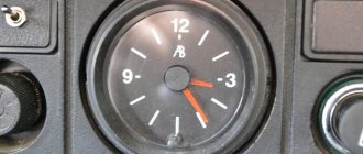
- watch;
- battery charge light;
- parking brake light;
- oil light;
- reserve.
Dashboard VAZ 2114
Each of these electronic elements is connected to the corresponding contact on the common panel. Which one, and to which one exactly – we’ll look at it below.
How does a starter work?
The starter is powered directly from the battery - a wire goes from the upper terminal of the solenoid relay to the positive terminal of the battery. The launch system works according to the following scheme:
- When you turn the ignition key, power is supplied to all components of the fuel system, the ECU.
- When the key is set to the “Start” position, power is supplied to the control output of the traction relay.
- The pull-in windings create a magnetic field, which causes the core to move.
- The power contacts close and the rotor begins to rotate.
- At the same time, the Bendix moves along the rotor axis, and the gear engages with the ring gear on the flywheel.
- The crankshaft begins to rotate, fuel is injected into the combustion chambers and high voltage is supplied to the spark plug electrodes.
Types of power units
The manufacturer of Gazelles business diesel, 402, 405, 406, 2705, 3302 and other models is the Gorky Automobile Plant.
Initially, two types of engines were used in the production and assembly of vehicles:
- carburetor engines produced at UMP;
- injection and carburetor engines supplied by ZMZ (Zavolzhsk enterprise).
Gazelle car diagram
The essence of this approach was to modernize and unify power units for business diesel models, 402, 405, 406, 2705, 3302 and others with UAZ and Volga vehicles. Of course, in the case of trucks, the electrical circuit diagram was redone.
For certain types of motors, different schemes were used:
- In vehicles with an internal combustion engine injector, the operation of the fuel mixture ignition system was initially more demanding in terms of operation. Such units were equipped with electronic ignition elements and injection control units. Of course, in such units the quality of the fuel plays an important role.
- As for carburetors, such options are considered more traditional today, but they also have certain features. Of course, the wiring diagram in carburetor engines is different from injectors.
In addition to the main models 402, 405, 406, 2705, 3302 and others, since 2001 the manufacturer began to produce a version called “business diesel”. In the case of a diesel engine, the wiring diagram has also undergone certain changes. In particular, such vehicles began to be equipped with a more powerful starter, battery, and generator (video author - MR. BORODA).
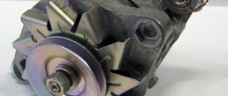
Generator design
The second power source of any car is the generator. It is necessary to power all consumers when the engine is running. The generator consists of the following parts:
- Rotary excitation winding.
- Slip rings on the rotor.
- Bearings.
- Front and back covers.
- Stator winding.
- Voltage regulator.
- Pulley with impeller.
- Diode block.
- Capacitor.
Voltage regulator operation
But there is one huge problem - depending on the crankshaft speed, the generator can produce voltage from 10 to 30 Volts, and such a variation is unacceptable. Therefore, it is necessary to stabilize the voltage at the same level - 12 V. In fact, of course, the generators produce a little more - 13.6-14.6 V. Only in this case will the battery be charged normally. You can stabilize the output voltage, but the problem is that the current consumption is very high.
And the zener diode must have considerable dimensions and, accordingly, cost. But it is much easier to stabilize the power supply to the rotor winding. If the voltage applied to it is stable, then the magnetic field will not change under any circumstances. This action is carried out using a voltage regulator. The maximum current consumption of the excitation winding is no more than 2 A. Structurally, the regulator is combined with a brush assembly.