General diagram of VAZ-1117, VAZ-1118, VAZ-1119
1 – right headlight; 2 – engine compartment lamp switch; 3 – sound signal, 4 – Lada Kalina starter; 5 – battery; 6 – generator; 7 – windshield wiper electric motor; 8 – left headlight; 9 – power window switch of the right front door (passenger]; 10 – power window motor of the right front door; 11 – right front door lock; 12 – connection block to the right front column; 13 – windshield washer motor; 14 – air temperature sensor; 15 – connection block to the injection system wiring harness; 16 – left front door lock; 17 – brake fluid level sensor; 18 – connection block to the left front column; 19 – right front door power window switch (driver); 20 – left front door power window switch; 21 – door lock switch in the switch block; 22 – electric window motor of the right front door; 23 – mounting block; 24 – immobilizer; 25 – power accessories control unit; 26 – instrument cluster; 27 – right side turn signal; 28 – glove compartment lighting lamp ; 29 – glove compartment lamp switch; 30 – brake light switch; 31 – ignition switch; 32 – lighting control module; 33 – steering column switch; 34 – left side direction indicator; 35 – connection block to the right rear column; 36 – rear door lock; 37 – rear window heating switch; 38 – reverse lock switch; 39 – alarm switch; 40 – heater motor switch; 41 – additional resistor; 42 – heater electric motor; 43 – block is connected to the left rear column; 44 – electric fuel pump with fuel level sensor; 45 – reverse lamp switch; 46 – handbrake sensor; 47 – cigarette lighter; 48 – reverse lock; 49 – connection block to the radio device; 50 – backlight lamps for heater control levers; 51 – Kalina illuminator; 52 – control unit for electromechanical power steering; 53 – interior lighting unit; 54 – right rear light; 55 – trunk locking motor; 56 – switch in the trunk lock; 57 – license plate lights; 58 – additional brake signal; 59 – rear window heating element; 60 – trunk lighting; 61 – left rear light
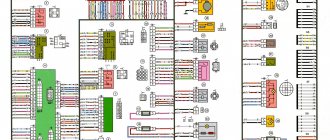
Elements of the instrument panel harness connection diagram
1, 3, 4, 5 — blocks of the tidy wire bundle to the front harness; 2, 8 - the same for the rear “pigtail” of wires; 6, 7, 9, 10 - continuation of the direction to the assembly unit; 11 — power supply for the lighting control device; 12 — set of instruments; 13 — toggle switch for the electric motor of the stove; 14 — power supply to the air supply box; 15 — ignition switch Lada Kalina; 16 — immobilizer block; 17 — block of the dashboard wiring harness to the ignition system wire bundle; 18 — cigarette lighter power supply; 19 — alarm switch; 20 — rear window heating switch; 21 — brake light switch; 22 — alarm light breaker; 23 — adjustment of computer modes ; 24 — windshield wiper control; 25 — VAZ horn switch ; 26, 27 — heating and ventilation control lighting lamps; 28 — glove box lighting; 29 — power supply to the on/off button in the glove compartment; 30, 31 — pinout for the standard radio; 32 — power supply to the electric motor of the stove; 33 — heater resistor network; 34 - electric amplifier control unit.
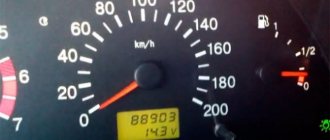
Signs of a malfunctioning speed sensor
If the DS is faulty, then the following signs appear:
- incorrect speedometer readings, the needle moves chaotically, complete speedometer failure;
- increased fuel consumption;
- The power steering refuses to work;
- the power unit check sign is on;
- The car odometer does not show mileage;
- the arrow indicating the fuel level fluctuates, making it impossible to correctly determine the level;
- the engine does not pull or has lost throttle response;
- The engine stalls at idle.
The listed symptoms can be caused by a breakdown of other devices (the author of the video is Autoelectrics HF).
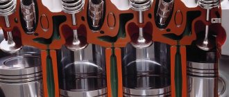
Detailed electrical diagrams of car components
Instrument panel wiring harness wiring diagram
1,2,3,4 blocks of the instrument panel wiring harness to the rear wiring harness blocks; 5,6 blocks of the instrument panel wiring harness to the blocks of the front wiring harness; 7 block of the instrument panel wiring harness to the block of the wiring harness of the air supply box; 8 block of the instrument panel wiring harness to the block of the front wiring harness; 9 lighting control module; 10 ignition switch; 11 on-board computer mode switch; 12 windshield wiper switch; 13 horn switch; 14 light signaling switch; 15 instrument cluster; 16 evaporator temperature sensor; 17 interior air temperature sensor; 18 air conditioner switch; 19 controller of the automatic climate control system; 20 heater damper gearmotor; 21 rear window heating switches; 22 alarm switch; 23 brake signal switch; 24 cigarette lighter; 25 electric power steering control unit; 26,27 connectors for the instrument panel wiring harness to the radio; 28 backlight lamp for the heater control panel; 29 lighting Lada Kalina; 30 mounting block: K3 additional starter relay; K4 additional relay; K5 relay breaker for direction indicators and hazard warning lights; K6 wiper relay; K7 relay for high beam headlights; K8 horn relay; K9 relay for turning on fog lights; K10 relay for turning on the heated rear window; K11 electric seat heating relay; K12 air conditioning compressor clutch activation relay; 31 heater motor switch; 32 electric heater motor; 33 additional resistance of the heater electric motor; 34 glove box lighting; 35 glove box lighting switch; 36 control unit of the automobile anti-theft system APS6; 37 driver airbag module; 38 passenger airbag module; 39,40 the instrument panel wiring harness blocks to the ignition system wiring harness blocks.
Electrical connection diagram for the wiring harness of the ignition system Lada Kalina 11174, 11184, 11194
1 oil pressure warning light sensor; 2 coolant temperature indicator sensor; 3 additional fuse box; 4 fuses for the electric fan of the engine cooling system; 5 electric fuel pump relays; 6 relays for the electric fan of the engine cooling system; 7 ignition relay; 8 relays 2 of the electric fan of the engine cooling system; 9 relay 3 of the electric fan of the engine cooling system; 10 electric fan of the engine cooling system; 11 throttle position sensor; 12 idle speed controller; 13 coolant temperature sensor; 14 diagnostic block; 15 ignition system harness block to the instrument panel harness block; 16 solenoid valve for purge the adsorber; 17 speed sensor; 18 ignition system harness block to instrument panel harness block 2; 19 mass air flow sensor; 20 crankshaft position sensor; 21 oxygen sensors; 22 controller; 23 rough road sensor; 24 diagnostic oxygen sensor; 25 ignition coil harness block to the ignition system harness block; 26 ignition coils; 27 ignition system harness block to ignition coil harness block; 28 spark plugs; 29 nozzles; 30 resistor; 31 air conditioning pressure sensors; 32 blocks of the ignition system harness and injector wiring harness; 33 phase sensor; 34 knock sensor.
Electrical connection diagram of the front VAZ-11184 wiring harness
1 headlight right; 2 right fog lamp; 3 speed sensor right front; 4 speed sensor left front; 5 air temperature sensor; 6 VAZ starter; 7 rechargeable battery; 8 generator; 9 blocks of the battery and starter harness and the front harness; 10 ABS hydraulic unit; 11 reverse light switch; 12 reverse lock; 13, 14, 15, 16 blocks of the front wiring harness to the blocks of the instrument panel wiring harness; 17 front wiring harness block to rear wiring harness block; 18 left headlight 11184; 19 left fog lamp; 20 electric washer motor; 21 beeps; 22 air conditioning compressor; 23 air conditioning fan electric motor.
Electrical connection diagram for rear wiring harness VAZ-11184
1 – 4 blocks of the rear wiring harness to the blocks of the instrument panel wiring harness; 5 rear wiring harness block to front wiring harness block; 6 side direction indicator, right; 7 left side direction indicator; 8 handbrake sensor; 9 blocks of the rear wiring harness to the rear right loudspeaker; 10 interior lamp; 11 reverse lock switch; 12 trunk light; 13 additional brake signal; 14 electric fuel pump module; 15 right lamp; 16 blocks of the rear wiring harness to the rear left loudspeaker; 17 rear window heating element; 18 rear wiring harness block to additional wiring harness block 3 (trunk lid); 19 rear wiring harness block to additional wiring harness block 2 (left rear door); 20 block of the rear wiring harness to the block of the additional wiring harness (right rear door); 21 left lamp 11184; 22 electrical package controller; 23 block of the rear wiring harness to the block of the rear additional wiring harness (left front door); 24 rear wiring harness block to rear additional wiring harness block 2 (right front door); 25 airbag control unit; 26 driver's seat belt pretensioner; 27 passenger seat belt pretensioner; 28 interior air temperature sensor; 29 right rear speed sensor; 30 left rear speed sensor; 31 electric heater for the right seat; 32 right seat electric heater switch; 33 left seat electric heater switch; 34 electric heater of the left seat.
Useful: Lada X-Ray diagram (Lada XRAY)
Diagram of electrical connections of the additional rear wiring harness (tailgate wiring harness) and the wiring harness of the license plate lights of the LADA KALINA 11174 car.
1 rear window wiper motor; 2 additional brake signal; 3, 4 blocks of the rear wiring harness, additional to the blocks of the rear wiring harness; 5 block to the trunk lock electric motor; 6 trunk lock; 7 rear window heating element; 8 block of the rear wiring harness, additional to the block of the wiring harness of the license plate lights; 9 block of the wiring harness for the license plate lights to the block of the rear additional wiring harness; 10, 11 license plate lights.
Electrical connection diagram for rear wiring harness VAZ-11174
1 – 4 blocks of the rear wiring harness to the blocks of the instrument panel wiring harness; 5 rear wiring harness block to front wiring harness block; 6 side direction indicator, right; 7 left side direction indicator; 8 handbrake sensor; 9 blocks of the rear wiring harness to the rear right loudspeaker; 10 interior lamp; 11 reverse lock switch; 12 trunk light; 13 block of the rear wiring harness to the block of the additional wiring harness; 14 electric fuel pump module; 15 right lamp VAZ-1174; 16 blocks of the rear wiring harness to the rear left loudspeaker; 17 rear wiring harness block to additional wiring harness block 3; 18 rear wiring harness block to additional wiring harness block 2 (left rear door); 19 block of the rear wiring harness to the block of the additional wiring harness (right rear door); 20 left lamp; 21 electrical package controllers; 22 block of the rear wiring harness to the block of the rear additional wiring harness (left front door); 23 rear wiring harness block to rear additional wiring harness block 2 (right front door); 24 airbag control unit; 25 driver's seat belt pretensioner; 26 passenger seat belt pretensioner; 27 interior air temperature sensor; 28 right rear speed sensor; 29 left rear speed sensor 1174; 30 electric heater of the right seat; 31 right seat electric heater switch; 32 left seat electric heater switch; 33 electric heater of the left seat.
Electrical connection diagram of the front VAZ-11174 wiring harness
1 headlight right; 2 right fog lamp; 3 speed sensor right front; 4 speed sensor left front; 5 air temperature sensor; 6 starter VAZ-1174; 7 rechargeable battery; 8 generator; 9 blocks of the battery and starter harness and the front harness; 10 ABS hydraulic unit; 11 reverse light switch; 12 reverse lock; 13, 14, 15, 16 blocks of the front wiring harness to the blocks of the instrument panel wiring harness; 17 front wiring harness block to rear wiring harness block; 18 left headlight Lada Kalina; 19 left fog lamp; 20 electric washer motor; 21 beeps; 22 compressor; 23 air conditioning fan electric motor; 24 rear window washer motor.
Electrical connection diagram for rear wiring harness VAZ-11194
1 – 4 blocks of the rear wiring harness to the blocks of the instrument panel wiring harness; 5 rear wiring harness block to front wiring harness block; 6 side direction indicator, right; 7 left side direction indicator; 8 hand brake sensor Lada Kalina; 9 block of the rear wiring harness to the block of the additional wiring harness; 10 interior lamp; 11 reverse lock switch; 12 trunk light; 13 electric fuel pump module; 14 right lamp VAZ; 15 rear wiring harness block to additional wiring harness block 3 (trunk lid); 16 rear wiring harness block to additional wiring harness block 2 (left rear door); 17 block of the rear wiring harness to the block of the additional wiring harness (right rear door); 18 left lamp 1194; 19 electrical package controller; 20 block of the rear wiring harness to the block of the rear additional wiring harness (left front door); 21 rear wiring harness block to rear additional wiring harness block 2 (right front door); 22 airbag control unit; 23 driver's seat belt pretensioner; 24 passenger seat belt pretensioner; 25 interior air temperature sensor; 26 speed sensor right rear; 27 left rear speed sensor; 28 electric heater of the right seat; 29 right seat electric heater switch; 30 left seat electric heater switch; 31 left seat electric heater.
Wiring diagram for fog lights
1 - fuse in the assembly block; 2 — immobilizer output; 4 — rear fog lights; 4— external optics control unit; 5 — ignition switch; A - to power supplies.
Causes of breakdowns
The cause of the DS malfunction may be:
- poor contact in the DS connector or its complete absence;
- violation of the integrity of the wiring, the wires oxidize and rust over time;
- contamination on sensitive elements;
- sensor element malfunction.
The first three reasons can be corrected without replacing the DS; in the latter case, the device must be changed.
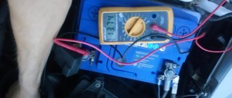
Checking the cleanliness of the connector
Lada Kalina fuse and relay diagram
The main mounting block for the vehicle's relays and fuses is located on the left side, behind the exterior lighting control panel. By pulling the tab on the left side of the instrument panel, we open the cover of the mounting block.
| № | A | Fuse function |
| 1 | 10 | Instrument cluster, immobilizer (APS-6), reverse lamp switch, direction indicators, automatic climate control system controller (luxury) |
| 2 | 30 | Window lifters Lada |
| 3 | 10 | Ignition switch (terminal 30), hazard warning switch |
| 4 | 20 | Wiper switch, wiper relay, front wiper motor, rear window defroster switch, airbag control unit, rear wiper, heated seat relay coil |
| 5 | 25 | Heater, electric power steering control unit, windshield wiper switch (window washer) |
| 6 | 20 | Sound signal |
| 7 | 10 | Brake light switch, interior lighting, on-board computer (instrument cluster), light control module (LCM), immobilizer (APS-6) |
| 8 | 20 | Heated rear window relay |
| 9 | 5 | Side lights on the right side, glove compartment lighting, immobilizer (APS-6) |
| 10 | 5 | Left side parking lights, license plate light, parking light indicator |
| 11 | 7,5 | Rear fog lamp, immobilizer (APS-6) |
| 12 | 7,5 | Right low beam, right light corrector gear motor, light switch, immobilizer (APS-6), light control module (LCM) |
| 13 | 7,5 | Left low beam, left light corrector gear motor, light switch, immobilizer (APS-6), light control module (LCM) |
| 14 | 10 | Right low beam, high beam indicator |
| 15 | 10 | Left high beam VAZ |
| 16 | 10 | Right fog lamp |
| 17 | 10 | Left fog lamp, light control module |
| 18 | 15 | Seat heating relay |
| 19 | 10 | ABS, light control module (LCM) |
| 20 | 15 | Cigarette lighter VAZ 1117/1118/1119 |
| 21 | 10 | Reverse lockout solenoid |
| 22 | 15 | Electrical package control unit, anti-theft system |
| 23 | – | – |
| 24 | 7.5 | A/C compressor clutch relay |
| 25 | 30 | Electrical package control unit |
| 26 | 25 | ABS |
| 27 | 5 | Spare |
| 28 | 7,5 | Spare |
| 29 | 10 | Spare |
| 30 | 20 | Spare |
| 31 | 50 | Electric power steering |
| 32 | 40 | ABS |
| Car relay | ||
| R1 | headlight washer | |
| R2 | Window lifters | |
| R3 | Starter VAZ 1117/1118/1119 | |
| R4 | Auxiliary relay (rear window defroster, heater, wiper and washer switch) | |
| R5 | Hazard warning and direction indicators | |
| R6 | Wiper | |
| R7 | High beam | |
| R8 | Sound signal | |
| R9 | Fog lights | |
| R10 | Heated rear window | |
| R11 | Heated seats | |
| R12 | Air conditioning compressor | |
The engine control system fuse box is located in the center console - under the protective cover.
- Diagnostic connector.
- 15 A. Main relay circuits (winding of the cooling system electric fan relay, canister purge valve, air flow sensor, speed sensor, oxygen concentration sensor, ignition coil).
- 15 A. Fuel pump, fuel pump fuse.
- 15 A. Constant power supply circuits of the controller (ECU).
The relays are located in the lower right part of the console, where the fuses for the electric fan of the Lada Kalina cooling system are attached.
Before replacing the fuse, the cause of the blown must be determined and eliminated. To avoid failure of engine control system elements, do not install fuses with an increased current rating or homemade bugs. Sometimes the fuse thread remains intact, while the connection inside the fuse is broken. It is impossible to determine such a malfunction by eye, and then you can assess the condition of the fuse using an ohmmeter.
with color schemes of the Lada Kalina in high quality can be found at the link
Power supplies Lada Kalina
The on-board network of the Lada is characterized by direct current, the nominal voltage of which is 12 V. The electrical circuit of the VAZ 1118 is single-wire. The main elements of the Kalina network can be divided into 4 groups.
- Sources.
- Consumers.
- Protective elements.
- Sensors
Sources and consumers of electrical energy are connected by negative terminals to a metal body (“ground”), which acts as a second wire. Power for all electrical devices of the Lada Kalina car is supplied from two main energy sources: a generator and a battery. While the engine is running, power is supplied to consumers from the alternator. When the engine is turned off, the devices are powered by a battery. While the generator is running, the battery is charged.
A generator is an alternating current synchronous eclectic machine. The rotating crankshaft of the car rotates the moving element of the generator - the rotor. In this way, the mechanical energy of the crankshaft rotation is converted into electricity. The rotor shaft rotates in bearings located in the covers. The bearings are lubricated at the factory with a material that does not require replacement until the end of the generator's service life. The stationary element of the generator - the stator - is tightened with four bolts to the generator cover.
The generator is the main source of electrical energy in Kalina. It supplies power to consumers when the engine is running. The generator is equipped with a built-in rectifier and voltage regulator. The Kalina stator includes a three-phase winding. The permissible voltage range of the generator is 14.4–15.1 V. The gear ratio of the engine to the generator is 1:2.4. The maximum generated current is 85 A.
The leads of the field winding located on the rotor are attached by soldering to copper slip rings on the rotor shaft. The generator voltage regulator is a non-separable part; if it breaks, it requires replacement. In order to protect the Lada's on-board network from voltage surges during ignition, a capacitor is connected between ground and the positive valve.
When the engine is turned off, all electrical appliances in the Lada Kalina are powered by the battery. In addition to the fact that the battery is an auxiliary source of energy for consumers, it helps to start the engine. In the electrical circuit of the Lada Kalina, a parallel connection is used for the generator and battery.
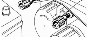
The negative contact of the battery is connected strictly to the body of the Lada, and the positive contact is connected only to the “B+” terminal on the generator. Do not remove the battery while the engine is running. This can lead to voltage surges in the network, resulting in damage to circuit elements.
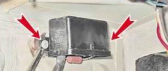
Removal and replacement instructions
To replace the device, you will need:
You will also need a new sensor - Kalinas may use different controllers, so before purchasing, find out exactly which one you need.
So, how to replace the sensor yourself:
- First, you need to turn off the power to the device and put the car on the parking brake by lifting the lever in the cabin.
- Open the hood. At this stage, you need to gain access to the sensor; for this, as we have already reported, you will have to remove the air duct going to the air filter. Alternatively, you can try to move it to the side. To remove, use a flat blade screwdriver to unscrew the clamps.
- Having seen the controller at the installation site, you will need to disconnect the wiring connector connected to it.
- Now take a wrench or socket and unscrew the nut that secures the sensor in its mounting location. The nut itself is located in an awkward place, so unscrewing it may take time. It may be that the nut is stuck to the mounting location, although this rarely happens. To unscrew it, treat the landing site with WD-40.
- Then take a flat-head screwdriver and disconnect the device from the transmission, and then remove it. Using a rag, clean the installation area; this can also be done before removing the sensor. Clean the surface thoroughly to prevent dirt from getting into the box itself.
- Now you can begin installing the new controller. Install the device and connect the connector with the wire to it. Don't forget to reinstall the air pipe.
Photo gallery “Changing the sensor with your own hands”
How to determine why the window regulator does not work
1. In the mounting block, check the power window fuse (F2, 25A) and relay (K2).
2. Remove the door trim and check the voltage at the power window motor terminals using a multimeter or a 12V test lamp.
If there is no voltage, then check the serviceability:
- power window buttons
- wiring (connector connection)
- electrical package control unit (central body electronics unit or CBKE), which is used in the “luxury” configuration.
If current flows to the electric motor, but the glass does not move, then we check:
- malfunction of the window lift motor (for example, the drive motor brushes are stuck/sticking, the plastic gear in the gearbox is worn out)
- The window lift cable is frayed
- glass is jammed (distorted)
The most common problems with power windows are:
- Window lift motor malfunction.
- Skewed, broken power window cable.
- Poor contact.
Let us remind you that on the website you can find solutions to other problems in the operation of the Lada Kalina 2, for example, squeaking clutch pedals.
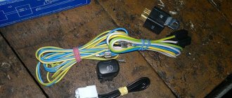
Kalina ESP buttons on VAZ 2110
There are two types of Kalinovsky ESP buttons: low-current (multiplex) and power. To install low-current ESP buttons, you will need to install an electrical package control unit/electrical package controller (2170-3763040). This will also allow you to close the doors and windows of the car with the key (the control is built into the key), there will be a two-stage door opening, and the ability to control electric mirrors and door locks from the power window unit. In the case of ESP power buttons, everything is much simpler, no additional control units are required. You just need to connect the buttons correctly.
Fan Resistor Functions
The Kalina cooling fan resistor is connected in series to the power supply circuit, which allows the engine to operate at different speeds. The resistance of the resistor changes depending on the temperature of the coolant and the load on the engine, and the current and speed of the fan motor change accordingly. This helps to eliminate sudden temperature changes and maintain optimal engine temperature in all engine operating modes. The fan resistor has a thermal fuse, which de-energizes the electric motor from overload (for example, when the shaft is jammed) and thereby protects the electrical wiring from fire.