Checking the VAZ 2105 voltage regulator
Checking the voltage regulator of the generator 37.3701
1 – battery;
2 – ground terminal of the voltage regulator;
7 – terminal “B” of the voltage regulator
Checking the voltage regulator of the G-222 generator
The operation of the voltage regulator is to continuously and automatically change the generator excitation current so that the generator voltage is maintained within specified limits when the generator speed and load current changes.
| Execution order | ||
Checking the removed regulator
|
What to do if the battery is boiling
You can conclude that the VAZ-2107 battery is “boiling” if the following problems occur:
- the corresponding indicator stops lighting;
- the voltmeter behaves inappropriately, and its needle goes to the right;
- A characteristic odor appears in the car interior.
“Boiling” of the battery is caused by problems with the voltage stabilizer. It is strictly forbidden to continue driving the car in such a situation: this can lead to breakdowns of all electrical equipment in the car. In order to get to the service center with safety for yourself and the car, you should forcefully turn off the generator set.
This can be done by physically removing the wire from the terminal with the abbreviation “61” located on the generator itself. The car will continue to move solely using the accumulated charge.
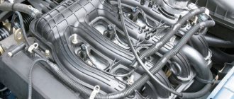
Technical characteristics of the VAZ 2105 generator
Starting in 1986, 37.3701 generators began to be installed on “fives”. Before this, the car was equipped with the G-222 device. The latter had different stator and rotor coil data, as well as a different brush assembly, voltage regulator and rectifier. The generator set is a three-phase mechanism with excitation from magnets and a built-in rectifier in the form of a diode bridge. In 1985, the relay responsible for indicating the warning light was removed from the generator. The on-board network voltage was monitored only using a voltmeter. Since 1996, the 37.3701 generator has received a modified design of the brush holder and voltage regulator.
Table: parameters of generator 37.3701 (G-222)
| Maximum output current (at a voltage of 13 V and a rotor speed of 5 thousand min-1), A | 55(45) |
| Operating voltage, V | 13,6–14,6 |
| Engine-generator gear ratio | 2,04 |
| Direction of rotation (drive side) | right |
| Generator weight without pulley, kg | 4,2 |
| Power, W | 700 (750) |
What generators can be installed on a VAZ 2105
The question of choosing a generator for a VAZ 2105 arises when the standard device is not capable of providing current to the consumers installed on the car. Today, many car owners equip their cars with powerful headlights, modern music and other devices that consume high current.
The use of an insufficiently powerful generator leads to undercharging of the battery, which subsequently negatively affects engine starting, especially in the cold season.
To equip your car with a more powerful source of electricity, you can install one of the following options:
- G-2107–3701010. The unit produces a current of 80 A and is quite capable of providing additional consumers with electricity;
- generator from VAZ 21214 with catalog number 9412.3701–03. The current produced by the device is 110 A. For installation, you will need to purchase additional fasteners (bracket, strip, bolts), as well as make minimal changes to the electrical part;
- product from VAZ 2110 for 80 A or higher current. For installation, a suitable mount is purchased.
Let's summarize:
As you can see, there are many reasons why the battery does not have charge. At the same time, a number of problems when the battery does not charge are common to different cars (for example, a VAZ 2107 is not charging or the battery of a foreign car is not charging). Moreover, some of them can be easily detected and eliminated with your own hands. The main thing is to determine why the battery is not charging, after which appropriate measures are taken.
Finally, we note that even ordinary car enthusiasts usually do not have problems with cleaning the terminals and restoring the integrity of wires and contacts. If the problem is with the generator, if you do not have the skills to repair it, it is only recommended to dismantle it yourself and then transfer the generator to a specialized service for repair. This will allow you to avoid common mistakes that are made when repairing a generator with your own hands, and also obtain a guarantee for the repaired device.
Source
Connection diagram for the “five” generator
Like any other electrical device in a car, the generator has its own connection diagram. If the electrical installation is incorrect, the power source will not only not provide the on-board network with current, but may also fail. Connecting the unit according to the electrical diagram will not be difficult.
Color-coded electrical wires are connected to the VAZ 2105 generator as follows:
- the yellow one from connector “85” of the relay is connected to terminal “1” of the generator;
- orange is connected to terminal “2”;
- two pink ones to terminal “3”.
Generator device
The main structural elements of a car generator are:
To know how the generator functions, you need to understand the purpose of each element in more detail.
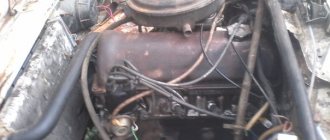
On the VAZ 2105, the generator is installed in the engine compartment and is driven by a belt from the engine crankshaft.
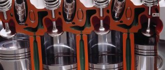
Rotor
The rotor, also known as the armature, is designed to create a magnetic field. On the shaft of this part there is an excitation winding and copper contact rings, to which the coil leads are soldered. The bearing unit, installed in the generator housing and through which the armature rotates, is made of two ball bearings. An impeller and a pulley are also attached to the rotor axis, through which the mechanism is driven by a belt drive.
Stator
The stator windings create an alternating electric current and are combined through a metal core made in the form of plates. To avoid overheating and short circuits between the turns of the coils, the wires are coated with several layers of special varnish.
Frame
The generator housing consists of two parts and is made of duralumin, which is made to facilitate the design. To ensure better heat dissipation, holes are provided in the housing. By means of an impeller, warm air is expelled from the device to the outside.
Generator brushes
The operation of a generator set is impossible without elements such as brushes. With their help, voltage is supplied to the rotor slip rings. The embers are enclosed in a special plastic brush holder and installed in the corresponding hole in the generator.
Voltage regulator
The relay-regulator controls the voltage at the output of the unit in question, preventing it from rising above 14.2–14.6 V. The VAZ 2105 generator uses a voltage regulator combined with brushes and fixed with screws on the back of the power source housing.
Diode bridge
The purpose of the diode bridge is quite simple - to convert (rectify) alternating current into direct current. The part is made in the shape of a horseshoe, consists of six silicon diodes and is attached to the back of the case. If at least one of the diodes fails, the normal functioning of the power source becomes impossible.
Carburetor internal combustion engine
Most classic VAZ models with a carburetor are equipped with a KSZ contact ignition system. Since 1987, cars began to be equipped with a contactless ignition system. The engine for the VAZ 2104 was created on the basis of the VAZ 2103 power unit, and accordingly, the VAZ 2103 electrical circuit was used.
Classic ignition
The KSZ includes a distributor (2), a coil (5), spark plugs (1), and connecting wires. The system also includes a capacitor (3), a relay (7), a breaker cam (4), a mounting block (6), and a switch (8).
On machines with KSZ, a distributor 30.3706-01 is installed. It is located on the left side of the cylinder block in the front part. Thanks to it, the circuit of the primary winding is interrupted and high voltage is distributed across the spark plugs in the required sequence. The distributor consists of ignition timing regulators, a high-voltage pulse distributor, and a breaker with contacts.
A B-117A with an open magnetic circuit is used as an ignition coil. It is located in the engine compartment and is attached to the left mudguard using two nuts. The device is used to convert low-voltage current into high-voltage current. The installed A17DVR spark plugs serve to ignite the fuel-air mixture in the cylinders of the power unit.
A VK347 type switch is installed, which has an anti-theft device. The anti-theft operating principle: when the key is removed from the lock in the “Parking” position, the locking rod extends, which blocks the steering shaft, entering a special groove.
Electronic ignition
The design of the contactless ignition system includes:
- distributor (distributor);
- sensor;
- switch that controls the system;
- high voltage coil;
- spark plug;
- connecting and high-voltage wires.
On VAZs with BSZ, a distributor 38.3706-01 is installed, its location coincides with the KSZ distributor. The coil consists of two windings. One is connected to the ignition switch relay, and the second is connected through a high-voltage wire to the distributor.
Using small cross-section wires, the coil and distributor are connected to a switch, which is responsible for the timely supply of a spark. The commutator converts the sensor pulses into a pulse current, which is supplied to the primary winding of the coil. The coil is also located in the engine compartment, like the KSZ coil.
The operating instructions contain an electrical diagram of the VAZ 21043 carburetor with a description of the main components included in it.
Electrical diagram of VAZ 2104
Operating principle of the generator set
The “five” generator functions as follows:
- When the ignition is turned on, power from the battery is supplied to terminal “30” of the generator set, then to the rotor winding and through the voltage regulator to ground.
- The plus from the ignition switch, through the fuse-link “10” in the mounting block, is connected to contacts “86” and “87” of the charge warning lamp relay, after which it is supplied through the contacts of the switching device to the light bulb and then to the minus of the battery. The light is on.
- As the rotor rotates, a voltage appears at the output of the stator coils, which begins to power the excitation winding, consumers and charge the battery.
- When the upper limit of the voltage in the on-board network is reached, the relay regulator increases the resistance along the excitation circuit of the generator set and keeps it within 13–14.2 V. Then a certain voltage is supplied to the winding of the relay responsible for the charge lamp, as a result of which the contacts open and the light goes out. This indicates that all consumers are powered by the generator.
Symptoms of a problem
You can determine that there are problems with electrical equipment by the following signs:
- Charger. The battery charging light flashes and goes out when the headlights are turned on. Knocks out the jumper in the voltage regulator. When the ignition is turned on, the charging indicator does not light up.
- Movement. Speed spontaneously increases when moving. Jerking when moving at low speed. Unstable idle. Loss of power during acceleration.
- Wiper. The wipers move jerkily. Windshield wipers do not turn on or do not work in rainy weather. The wipers move jerkily.
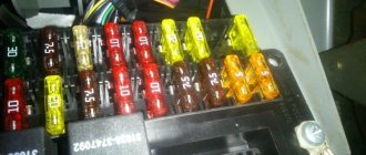
- Closures Fuse No. 9 burns out after turning on the ignition or at the start of movement. Fuse #1 blows. Fuse No. 7 burns out when the lights are turned on.
- Dashboard. When the power grid is loaded, the devices begin to display incorrect values.
- Start the engine. Doesn't turn or...
- Lighting fixtures do not work.
Basic electrical wiring faults: short circuit or break.
In the event of a short circuit, fuses, relays, devices burn out, and even a fire is possible. In the event of a break, either some node, system or device, device, etc. fails. You need to be able to understand the wiring diagram of VAZ 2103, 2104 and other models, find and fix faults (video author - MR.BORODA).
Generator check
If problems occur with the generator set, a unit check must be performed to determine the cause. This can be done in several ways, but the most accessible and common is using a digital multimeter.
Diagnostics with a multimeter
Before starting the test, it is recommended to warm up the engine at medium speed for 15 minutes, turning on the headlights. The procedure is performed as follows:
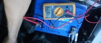
- We turn on the multimeter to measure voltage and take a measurement between terminal “30” of the generator and ground. If everything is in order with the regulator, then the device will show a voltage in the range of 13.8–14.5 V. If the readings are different, it is better to replace the regulator.
- We check the regulated voltage by connecting the probes of the device to the battery contacts. In this case, the engine should operate at medium speeds, and consumers should be turned on (headlights, heater, etc.). The voltage must correspond to the values installed on the VAZ 2105 generator.
- To check the armature winding, connect one of the multimeter probes to ground, and the second to the rotor slip ring. At low resistance values, this will indicate a faulty armature.
Video: diagnosing a generator with a light bulb and a multimeter
To be able to constantly monitor the battery charge voltage, I installed a digital voltmeter in the cigarette lighter, especially since I am not a smoker. This device allows you to always monitor the voltage of the on-board network without leaving the car and without lifting the hood to take measurements. A constant voltage indication immediately makes it clear that everything is in order with the generator or, conversely, if problems have arisen. Before installing the voltmeter, more than once I had to deal with problems with the voltage regulator, which were detected only when the battery was discharged or when it was being recharged, when the liquid inside simply boiled due to the excess of the output voltage.
At the stand
Diagnostics at the stand are carried out at the service, and if everything necessary is available, it is also possible at home.
- We mount the generator on the stand and assemble the electrical circuit. On the G-222 generator we connect pin 15 to pin 30.
Oscilloscope
Generator diagnostics are possible using an oscilloscope. However, not everyone has such a device. The device allows you to determine the health of the generator based on the signal shape. To check, we assemble the same circuit as in the previous diagnostic version, after which we perform the following steps:
- On the generator 37.3701, we disconnect the “B” terminal from the diodes from the voltage regulator and connect it to the battery positive through a 12 V car lamp with a power of 3 W.
- We turn on the electric motor on the stand and set the rotation speed to about 2 thousand min-1. We disconnect the battery using the toggle switch “6” and set the output current to 10 A using the rheostat.
- Using an oscilloscope, we check the signal at terminal “30”. If the winding and diodes are in good condition, the shape of the curve will be in the form of uniform saw teeth. In case of broken diodes or a break in the stator winding, the signal will be uneven.
VAZ 2104 no battery charging
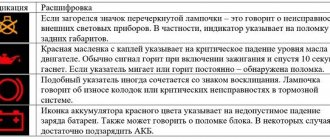
The VAZ 2104 car has a voltmeter and a warning lamp on the instrument panel to monitor the battery charge.
| Instrument panel of a VAZ 2104 car. The numbers indicate: 18 - rear fog light switch; 17 — fuel reserve warning lamp; 16 — fuel level indicator; 15 — instrument cluster; 14 - voltmeter ; 13 — control lamp for turning on side lights; 12 — control lamp for turning on the direction indicators; 11 — control lamp for turning on the high beam headlights; 10 — three-position switch for electric heater fan; 9 — plugs for screws securing the instrument panel; 8 — rear window heating switch; 7 — summing counter of the distance traveled; 6 — speedometer; 5 — block of warning lamps; 4 - battery charge indicator lamp; 3 — liquid temperature indicator in the engine cooling system; 2 - warning lamp for insufficient oil pressure in the engine lubrication system; 1 — external lighting switch; |
In cases where the voltmeter is not in the green zone and the control lamp is on, this indicates that the VAZ 2104 is not charging the battery. This could be due to several reasons.
First of all, the fuse in the battery charging circuit and the reliability of its fixation in the mounting block are checked.
The second thing you need to pay attention to when troubleshooting is the alternator drive belt. The belt must not be worn, twisted and have the required tension.
The deflection of the alternator belt should normally be 10-15 mm when pressed by hand.
In addition, it is worth inspecting the generator drive pulley, which may also be worn out, and the belt will simply slide along its surface without turning the generator rotor. In such cases, both the pulley and the belt must be replaced.
Next, you need to check the output voltage from the generator, and if it is normal and shows 13.5 -14.2V, then check the wire from the generator to the battery for the integrity and reliability of its connection.
The terminals on the battery itself may be oxidized or may not have reliable contact with the battery terminals.
| When operating, the VAZ 2104 voltmeter should be in the white or green areas. Occasionally, it is necessary to check the voltage of the on-board network with independent devices in order to be confident in the readings of the built-in voltmeter. |
The oxidized terminals are cleaned (a solution of soda and water), and the unreliable contact is tightened.
Further, the reason why the VAZ 2104 does not charge the battery may be the generator brushes, which either have extreme wear or are stuck in the brush holder guides. Worn brushes are replaced and jamming is eliminated.
In addition, the slip rings may have wear and tear and the brushes cannot lie completely on the rings, so there is no reliable contact in the excitation circuit
Also, the reason for the lack of charging may be a faulty relay-regulator combined with the brush assembly. In such cases, the relay-regulator along with the brush assembly must be replaced.
The lack of charging can be affected by an interturn short circuit, a short to ground or a break in the stator winding, as well as a break in the generator excitation circuit.
In the generator, the diodes of the rectifier unit (popularly “horseshoe”) can also fail, as well as a short circuit or breakdown of one of the additional diodes.
In addition, the generator may have poor contact with the car body (ground) or unreliable contact at terminal “30”
Also read other reviews
- VAZ 2106 battery light is on
Source
Repair of VAZ 2105 generator
Having determined that the generator needs repair, it must first be removed from the car. To perform the operation you will need the following tools:
- keys for 17 and 19;
- heads for 10, 17 and 19;
- ratchet handle and knob;
- extension with cardan joint.
How to remove the generator
We dismantle the unit in the following order:
- Remove the negative terminal from the battery and disconnect the wiring from the generator.
Generator disassembly and repair
To disassemble the mechanism you will need the following list of tools:
- wrench and socket 10 with extension;
- hammer and adapter made of soft metal;
- bearing puller;
- crosshead screwdriver.
The operation consists of the following steps:
- Using a Phillips screwdriver, unscrew the fastening of the relay-regulator to the housing.
Video: generator repair on a “classic”
Types of relay regulators
All regulators that were used on VAZ cars at different times can be of only two types:
- External regulator.
- Three-level internal regulator.
Starting with the 2105 and 2107, the factory installed only internal relays on the alternator. External ones were used on older models and they were removed from the generator, since they were not particularly compact. On these machines, the relay was installed under the hood on the mudguard on the left.
If there was a need to replace the external regulator, then this was done easily and simply - it was in an accessible place, attached directly to the body with self-tapping screws, and was simply removed. The main thing that needed to be taken into account when replacing it was the correspondence of the terminals to pins 67 and 15. It was enough to simply check the correct connection of the new relay using the diagram, start the engine and take the measurement again.
Generator belt
The flexible drive is designed to rotate the pulley of an electricity source, ensuring the functioning of the latter. Insufficient tension or a broken belt leads to a lack of battery charge. Therefore, despite the fact that the belt life is about 80 thousand km, its condition must be periodically monitored. If damage is detected, such as delamination, protruding threads or tears, it is better to replace it with a new product.
Many years ago, when I first purchased a car, I encountered an unpleasant situation - the alternator belt broke. Fortunately, this happened near my house and not in the middle of the road. I had to go to the store to buy a new part. After this incident, I always carry an alternator belt in stock, because it does not take up much space. In addition, when I carry out any repair work under the hood, I always check the condition of the flexible drive and its tension.
The VAZ Five uses an alternator belt 10 mm wide and 944 mm long. The element is made in the shape of a wedge, which allows it to more easily engage with the generator pulley, pump and crankshaft.
How to tension the alternator belt
To tension the belt you will need the following tools:
- mount;
- head for 17 and knob.
The procedure consists of the following steps:
- Check the tension level of the drive. Normal values are those at which the belt between the pump pulley and the crankshaft pulley bends by 12–17 mm or by 10–17 mm between the pump pulley and the generator pulley. When taking measurements, the pressure should not be more than 10 kgf in the location indicated in the image. To do this, press with the thumb of your right hand with moderate force.
How the relay works
This device on the VAZ-2107 (both carburetor and injector) is located in the same housing as the brush mechanism.
Its main purpose is to stabilize the voltage coming out of the generator. Not so long ago, relays made in the form of an electronic board were sold in stores. It had one drawback - a relatively short service life. Such devices could not be disassembled and were simply replaced with serviceable ones when they broke down.
Modern analogues are slightly smaller in size and use a semiconductor. The old type of relay can no longer be found. The new version is in no way inferior to it functionally and is also capable of reliably regulating voltage in the range from 13.2 volts to 14.8. Exceeding the last value when measured with a tester on the battery clearly indicates a breakdown of the relay.