01/26/2022 15,387 VAZ 2107
Author: Ivan Baranov
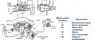
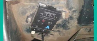
As with any car, the generator on the VAZ 2107 injector works in parallel with the battery - these are two power sources for the car, which are used in different modes. The article discusses the generator 37.3701, the principle of operation of the generator with different characteristics, including a maximum current of 80 Amperes, and provides instructions for connecting the unit. The G222 generator set is similar, you just need to pay attention to some differences.
[Hide]
Carburetor engines
The connection diagram for the VAZ-2107 generator (carburetor and injector) depends on the year of manufacture of the car. The first carburetor models had a G-222 generator installed. The same device can be found on commercially produced VAZ-2105 and VAZ-2104 models with a carburetor injection system.
The maximum output current for such an installation is 55 amperes. But in recent years, cars with fuel injection systems have become widespread. Its use implies a large current consumption, so it is necessary to use a generator with a high current to ensure a normal charge level and power supply to all consumers.
How does the generator 2106 2107 work?
Correct operation of the generator 2106 2107 ensures the proper functioning of all vehicle devices. According to the attached operating instructions, the technical condition of the VAZ 2106 generator is checked at least once every 4 months. Failure to pay attention to this requirement leads to wear and tear of the device. As a result, the question of which generator is better to install on the VAZ 2106 becomes relevant.
If the car is involved in an accident or major repairs, it is imperative to ensure that the device is in working order. Otherwise, the voltage drop will cause serious damage to all electricity consumers in the car. In most cases, a VAZ generator malfunction can be repaired in a garage.
Injection engines
On injection engines, generator sets 5142.3771 or similar are used. They have increased energy, the maximum current is about 80-90 A, it all depends on the design option. Cars of the seventh series and similar models are good because they are like a designer set. You can install almost any generator on them, similar in design to the “native” one.
For tuning, installations with an output current of 100 amperes and higher are used. But the use of such devices is justified only if many powerful consumers are connected to the electrical equipment. Regardless of the design, the generators produce alternating current; a voltage regulator, capacitor and diode block are installed in the housing.
Types of breakdowns
What problems occur if the generator is not working properly?
- Extraneous noise appears.
- Complete lack of battery charging while the engine is running.
- Overheating and failure of the same battery.
- Damage to any or all energy consumers, including the injector.
- Increased or decreased voltage in the electrical system. The standard voltage is 13.6-14.5 V.
- Mechanical or electrical damage to the elements of the generator itself.
Obviously, this node requires special attention.
Cars before 1986
The G-222 generator was used in cars. The connection diagram for the VAZ-2107 is almost the same as on later models. But there are features, among the main ones - there is a control lamp indicating battery charging. Moreover, it worked using an electromagnetic relay.
When the ignition is turned on, power is supplied from the lock through the instrument panel fuse to the electromagnetic relay of the battery charge lamp and the coil contact. The second contact of the coil is connected to the center wire on the generator (the point where the three windings connect).
The electromagnetic relay has normally closed contacts, so when the ignition is turned on, the lamp lights up. But as soon as the engine starts running, the generator produces current. And a current flows through the control lamp coil, which causes the armature to attract and open the contacts.
At the same time, the power to the incandescent lamp stops and it goes out. This indicates that the battery is charging normally. Only when the power supply to the lamp stops will voltage be applied to the excitation winding and the generator will be able to return to operating mode.
What factors should you consider when purchasing a new generator?
When choosing a generator for VAZ cars, it is necessary, first of all, to calculate the total power of all energy-consuming devices and devices in the on-board electrical network. The power of the power source must exceed this total value by 20%.
The type of engine must be taken into account when choosing a generator model. A generator paired with a gasoline engine can be compact and more economical. A diesel generator should be larger and more expensive.
The choice of generator also depends on the technology of combustion of the fuel-air mixture in engines of various types:
- In gasoline engines, fuel is supplied using a carburetor or injector. Here, the fuel-air mixture is sucked into the combustion chamber due to the vacuum created. There it is compressed and ignited by a spark from the spark plug. In this case, the supply of mixture to the combustion chamber is not regulated (does not depend on engine speed).
- Diesel engines use only an injector. Here the combustible mixture is injected into the combustion chambers under pressure and enters through the nozzles. Their opening is regulated by an electronic device (controller) with many sensors that respond to the speed of the vehicle, the voltage in the on-board electrical network and other indicators. Such engines consume less fuel, but are more energy-intensive due to the presence of auxiliary electronic devices. A car with such an engine requires a more powerful generator.
Installing a weak power source on the “injector” will lead to its rapid breakdown and damage to the battery.
Cars manufactured in 1996 and later (carburetor engines)
The connection diagram for the G222 generator on a VAZ-2107 after 1996 differs from the previous one in one small feature - the power supply to the excitation winding has been changed. Cars have been improved, and some improvements make it possible to kill two birds with one stone - simplify the design and make the fate of the driver easier.
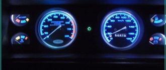
After 1996, instead of a warning lamp, they began to install a voltmeter, which more or less accurately shows the battery charge level. And if the lamp allows you to monitor only the presence or absence of voltage on the generator, then using a voltmeter the driver visually assesses the level. And if necessary, it can understand that repairs or maintenance are necessary.
Completion
The most typical and common breakdowns were presented. For correct diagnosis in serious cases, special stands are needed, which are present in many workshops. It should be noted that sometimes the cost of such repairs can be equal to or even exceed the price of a new generator. Therefore, repair is not always the answer.
From the text it becomes clear that there are no significant differences between the injection VAZ 2107 and the earlier carburetor version. The same applies to the modification of the VAZ 21074 and all others.
Generator manufacturers claim that the generator is designed for 200-250 thousand kilometers. After passing the barrier of 100-150 thousand, it is necessary to conduct a thorough inspection and lubricate all mechanical connections.
Generator circuit for injection engines
In fact, the design of the generator set is not much different from those installed on carburetor engines. Only the type of excitation and serviceability monitoring differ. The dashboard contains not only a warning lamp, but also a voltmeter; these two devices allow you to assess both the presence and level of charging. Current flows through the lamp filament and is supplied to the field winding when the engine starts. The connection diagram for the VAZ-2107 generator, regardless of the year of manufacture, implies operation in the following mode:
- When the ignition is turned on, power is supplied to the excitation winding. A magnetic field appears around the armature.
- When the crankshaft rotates with the starter, the generator armature also begins to move. With the help of movement and a magnetic field, a potential difference arises at the ends of the stator windings.
- From the windings, voltage (alternating, three-phase) is supplied to the rectifier unit, and from it to terminal “30” of the generator.
- Pin “30” is connected to the battery (positive terminal). Consequently, the entire electrical system is powered and the battery is charged.
In this case, the battery and generator G221A work in parallel. The connection diagram for the VAZ-2107 with carburetor and injection engines is almost identical, with only minor features.
000shema_el.jpg
Next, let's get to work:
-Remove the unit from the engine and, using the “ten” key, unscrew the nut from terminal “30”. We remove the capacitor wire.
-Unscrew the fastening screw and remove the capacitor.
-Remove the charging relay and the corresponding insulating washer.
-Unscrew the fastening nut from the pulley.
-We disassemble the pulley and impeller.
-Remove the ring installed behind the key.
-Pull the front cover off the rotor shaft
-Remove the adjusting washer (don’t forget to put it back when installing).
-Using the “8” wrench, unscrew the nuts that hold the bearing
-Remove the outer and inner bearing caps.
-Knock out the bearing.
- Press in a new bearing. To do this, you need to apply several light blows through a special mandrel.
-Re-lock the nuts.
-Knock out the anchor from the back cover. We remove it together with the rear bearing.
-If it needs to be replaced, remove it from the rotor shaft.
-Unscrew the three nuts that secure the stator terminals to the diode bridge.
-We take out three bolts from the back cover along with special insulating gaskets.
-Remove the diode bridge and winding.
It is better to replace, if necessary, the diode bridge assembly. We clean all generator parts from dirt, dust and oil. We perform assembly in reverse order.
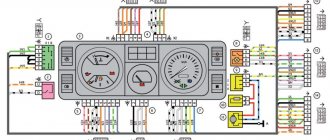
Electrical diagram VAZ-2107 carburetor
Electrical diagram of VAZ 2107, 21074 produced in 1988-2001 with generator 37.3701
- block headlights
- side direction indicators
- accumulator battery
- starter relay
- carburetor electro-pneumatic valve
- carburetor microswitch
- generator 37.3701
- gearmotors for headlight cleaners *
- Fan motor switch sensor
- engine cooling fan motor
- sound signals
- distributor
- spark plug
- starter
- coolant temperature gauge sensor
- engine compartment lamp
- low oil pressure warning sensor
- low brake fluid level indicator sensor
- windshield wiper motor
- carburetor electro-pneumatic valve control unit
- ignition coil
- headlight washer pump motor *
- windshield washer pump motor
- mounting block
- windshield wiper relay
- hazard warning and direction indicator relay
- brake light switch
- reverse light switch
- ignition relay
- ignition switch
- three lever switch
- hazard switch
- socket for portable lamp**
- heater fan switch
- additional resistor for the electric motor of the heater (stove)
- rear window heating indicator lamp
- low brake fluid level warning lamp
- signaling unit
- heater fan electric motor
- glove compartment lamp
- light switches on the front door pillars
- switches for warning lights of open front doors ***
- front door open warning lights ***
- connection block
- cigarette lighter
- watch
- instrument light switch
- diode for checking the serviceability of the low brake fluid level indicator lamp
- fuel level indicator
- fuel reserve indicator lamp
- speedometer
- turn signal indicator lamp
- carburetor choke indicator lamp
- battery charge indicator lamp
- carburetor choke warning switch
- instrument cluster
- econometrician
- light switches on the rear door pillars
- coolant temperature gauge
- tachometer
- parking brake indicator lamp ("handbrake")
- low oil pressure warning lamp
- high beam indicator lamp
- indicator lamp for turning on external lighting
- voltmeter
- parking brake indicator switch ("handbrake")
- outdoor light switch
- rear window heating switch with backlight
- rear fog light switch with on/off indicator *
- fog light circuit fuse
- lampshade ****
- tail lights
- level indicator and fuel reserve sensor
- connectors for connecting to the rear window heating element *
- license plate lights 2107
Wiring diagram VAZ-2107 carburetor - full view:
Mounting block connection diagram
P1 — relay for turning on the heated rear window; P2 - relay for turning on the headlight cleaners and washer; P3 - relay for turning on sound signals; P4 - relay for switching on the electric motor of the engine cooling system fan; P5 - headlight high beam relay; P6 - low beam headlight relay; A - the order of conditional numbering of plugs in the mounting block blocks. The outer number with the letter “Ш” in the plug designation is the block number, and the inner number is the conventional number of the plug.
Schemes of individual blocks of the seven
Power supply system
Power plant starting system
1 - starter; 2 - relay; 3 — ignition switch; 4 - battery
Ignition system
1 - generator; 2 — ignition switch; 3 - distributor; 4 - breaker; 5 — candles; 6 - coil; 7 - battery
Contactless ignition system
External and internal lighting
Windshield wipers and washers
1 — electric motors of the windshield wiper; 2 — washer motor; 3 — mounting block; 4 — ignition switch; 5 - washer switch
Cooling Fan
1 — fan electric motor; 2 - sensor; 3 — mounting block; 4 - ignition relay; 5 - ignition switch.
Wires for connecting electrical appliances
| Connection type | Section, mm 2 | Insulation color |
| Negative terminal of the battery - vehicle ground (body, engine) | 16 | Black |
| Starter positive terminal - battery | 16 | Red |
| Positive contact of the generator - plus battery | 6 | Black |
| Generator - black connector | 6 | Black |
| Terminal on the generator “30” – white MB block | 4 | Pink |
| Starter connector “50” – starter relay | 4 | Red |
| Starter Start Relay - Black Connector | 4 | Brown |
| Ignition switch relay - black connector | 4 | Blue |
| Ignition switch output “50” – blue connector | 4 | Red |
| Ignition switch connector “30” – green connector | 4 | Pink |
| Right headlight plug - ground | 2,5 | Black |
| Left headlight plug - blue connector | 2,5 | Green, gray |
| Generator output “15” – yellow connector | 2,5 | Orange |
| Right headlight connector - ground | 2,5 | Black |
| Left headlight connector - white connector | 2,5 | Green |
| Radiator fan - ground | 2,5 | Black |
| Radiator Fan - Red Connector | 2,5 | Blue |
| Ignition switch output “30/1” – ignition switch relay | 2,5 | Brown |
| Ignition switch contact “15” – single-pin connector | 2,5 | Blue |
| Right headlight - black connector | 2,5 | Grey |
| Ignition switch connector “INT” – black connector | 2,5 | Black |
| Six-pin block of the steering column switch - “ground” | 2,5 | Black |
| Two-pin block of the steering column switch - glove box illumination lamp | 1,5 | Black |
| Glove compartment light - cigarette lighter | 1,5 | Black |
| Cigarette lighter - blue block connector | 1,5 | Blue, red |
| Rear window defroster - white connector | 1,5 | Grey |
Car wiring diagram
1 – radiator fan drive motor; 2 – relay and fuse block (mounting block); idle speed sensor; 4 – engine control unit; 5 – potentiometer; 6 – set of spark plugs; 7 – ignition control unit; 8 – electronic crankshaft sensor; 9 – electric fuel pump; 10 – tachometer 2107; 11 – lamp for monitoring the health of electronic systems; 12 – ignition system control relay; 13 – speed sensor; 14 – diagnostic connector; 15 – set of injectors; 16 – adsorber solenoid valve; 17, 18, 19 – fuse block protecting the injection system circuits; 21 – electronic fuel pump control relay; 22 – electronic relay for controlling the intake pipe heating system; 23 – intake pipe heating system; 24 – fuse protecting the heater circuit; 25 – electronic oxygen level sensor; 26 – cooling system temperature control sensor; 27 – electronic air damper sensor; 28 – air temperature sensor; 29 – pressure control sensor.
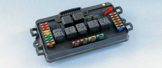
Fuse and relay diagram 2107
On newer “sevens” a block with 17 fuses and 6 relays is installed. VAZ 2107 fuses on the “new” unit protect the following electrical circuits and devices:
- Reversing lamps, heater fan, rear window defroster warning lamp and relay, rear wiper motor and rear washer pump.
- Electric motor for front wipers.
- Reserve socket.
- Reserve socket.
- Power supply for heated rear window.
- Clock, cigarette lighter, power socket “carrying”.
- Signal and radiator fan.
- Turn signal lamps in emergency mode.
- “Fog lights” and a relay that regulates the voltage of the on-board network.
- Instrument panel lamps.
- Brake light bulbs.
- Right high beam headlight.
- Left high beam headlight, high beam warning lamp.
- Side lights (rear right, front left), license plate and engine compartment lighting.
- Side lights (rear left, front right), glove compartment and cigarette lighter lamps.
- Low beam (right lamp).
- Low beam (left lamp).
The block relays perform the following functions:
- Heated rear window relay.
- Headlight cleaner and washer relay.
- Signal relay.
- Cooling system electric fan relay.
- High beam relay.
- Low beam relay.
The fuse block of the VAZ 2107 (injector) is no different from the block on the carburetor “seven”. Injection models are simply equipped with an additional relay and fuse box installed in the cabin under the glove compartment. The block includes three relays - the “main” relay, the fuel pump relay and the fan relay.
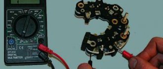
External inspection
External inspection reveals obvious damage. If necessary, spare parts are cleaned of dirt, oil and moisture. Solid particles of sand contribute to the development of bearings and brushes. It is important to know that water entering the housing can damage the varnish coating of the windings. An insulation breakdown threatens an interturn short circuit of the stator coils. Also, a layer of dirt can short circuit pin 30 to ground. A short circuit will damage the semiconductor rectifiers.
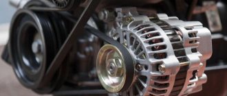
Particular attention is paid to the condition of the belt drive on the “Seven” and VAZ-2105. The belt is classified as a fast-wearing spare part. Visually determine the absence of cuts, worn out teeth, or frayed edges.
It is useful to observe the operation of the flexible transmission with the hood open. The approach of a critical state can be heard by sound. Belt slipping is one of these problems. As a result of its friction against the pulley, a characteristic whistle occurs.
Excessive wear will indicate that the damaged belt needs to be replaced. Otherwise, slipping will lead to loss of battery charging and damage to the coolant pump. The battery will run out and the motor will overheat.
The generators on the VAZ-2107 car (injector or carburetor type) have the same drive. But there is one difference - the crankshaft position sensor is not installed on the carburetor.
The degree of production increases if the tension is incorrectly adjusted. The situation is corrected by moving the body along the adjustment bar, having first loosened the fastening. Installation of the generator in place is fixed with a 17 nut and a 19 lower bolt.
The measurement is carried out by pressing on the belt. Pressure is applied with a mounting blade in the middle of the segment. The deflection between the generator and the water pump will be 12-17 mm. The right wing (directed towards the crankshaft) will bend by 10-15 mm.