Design Features
A novice car enthusiast is recommended to study the operation of an injection engine. The injector includes a system that injects gasoline. After familiarizing yourself with the device, you won’t have to contact a service center for minor problems, but rather fix them at home yourself. The fuel supply is considered distributional, because gasoline is injected into each cylinder using a specific injector.
The VAZ 2115 is based on the VAZ 21099 model. In the new car, unlike the previous one, the shape of the hood, rear and front bumpers, a new configuration of the front wings, as well as improved aerodynamics of the body have changed. A spoiler was placed on the trunk lid - a wing. The exterior decoration was decorated with plastic elements, since metal ones were corroded by corrosion. For added safety, the model was supplemented with a brake signal and rear lighting.
Thanks to the electronically controlled injection power unit located under the hood, the electrical circuit of the VAZ 2115 differs significantly from the 99 modification.
The supporting structure of the car body is welded, metal, integral. The drive is front transverse. It has a 5-speed gearbox and the front wheels are connected to the drive. The engine has a capacity of 1.5 liters and is a four-cylinder, petrol, four-stroke and in-line. Distributive fuel injection systems are controlled electronically.
Under the rear seats, behind the bottom, there is a fuel tank. Gasoline is supplied from the gasoline pump located in it. The pressure level in it should not fall below 3.2 bar.
Hidden interior sub-cabinet wiring connects the located equipment. The mounting block is placed in the engine compartment. It consists of powerful consumers: wipers, high beam headlights, starter. All of them are connected to the on-board network using an intermediate relay.
Fuel pump design
As for the element itself, it is of a membrane type. Its operating principle is based on an electric drive. The motor is powered from the vehicle's network. The main component is a special membrane, which can perform reciprocating movements during engine operation.
The membrane system or hydraulic supercharger assembly must have a safety valve in its design, which serves to relieve pressure. There is also a check valve located in the outlet part of the device. It is necessary to prevent fuel from penetrating from the power system into the tank. In addition, it helps maintain pressure in the system when the pump is turned off.
As for the operating principle of a mechanical hydraulic supercharger, they are divided into centrifugal and positive displacement pumps. The first can be of the turbine type, where the working part is similar to an impeller with a huge number of blades.
In a VAZ-2114 car, the fuel pump is constantly washed with flammable liquid, even if there is not much fuel in the tank. This design is used to keep the electric motor cool, because during operation it gets quite hot.
Ignition system and starter connection diagram
The VAZ wiring diagram includes a VAZ ignition system module, consisting of two high-voltage transformers and two electronic control units. They are in a durable plastic case, from which 4 high voltage wires are removed. They have a connection that creates a synchronous passage of a spark entering the cylinders of the power plant.
The VAZ 2114 ignition module consists of a two-spark coil and is of the block type. The ignition switch turns on a relay that sends a signal to the controller. The latter is the control element of the injection system for starting the fuel pump. It is connected to the cleaning filter with a flexible hose. After this, gasoline is supplied to the fuel rail, from which the fuel is supplied to the injectors.
The pinout of the VAZ ignition switch is in itself. It has an anti-theft device. When the lock socket illumination is on and the engine is running, the anti-theft locking device blocks the VAZ starter from re-engaging.
The starter connection diagram consists of:
- the starter itself;
- generator;
- rechargeable batteries;
- ignition switch;
- two relays.
The engine for the VAZ 2114 is also a four-stroke injector, in-line with an 8-valve unit. Its camshaft is at the top. Operates on gasoline fuel and is equipped with 4 cylinders. It is cooled with a special liquid solution. The engine compartment contains a motor located perpendicular to the direction of movement.
The VAZ wiring diagram has electronics that control the injection system. It operates at low voltage, so it can be damaged very easily by electrostatic discharge. To prevent this from happening, do not touch the circuit elements on the boards or the ECU plugs.
Signs of damage
The first sign that indicates that the pump is not working is a banal engine refusal to start.
Another point is the pressure in the fuel system. When everything is in order with the device, then there will be 3.2 bar in the lines. Along the fuel rail on a 1.5-liter engine, the pressure level will be from 285 kPa to 325, on a 1.6-liter engine - from 375 to 390 kPa.
It also often happens that the pump does not receive a signal after turning on the ignition. Usually the driver hears a slight vibration, which indicates that the device is working normally, but in this case there is no vibration. Most often the problem here is in the wiring. The engine may jerk even before starting or just at low speeds. The pump itself or the coarse filter mesh do not function here.
All these problems can be corrected. Don't immediately run to the nearest store. Replacing a VAZ-2114 fuel pump will cost from 2,000 rubles when purchasing a whole module, or 1,000 rubles when purchasing only the pump. Causes may also include a fuse, relay, loose ground, electric motor, or contacts.
Electrical circuit design of VAZ 2115
The VAZ wiring diagram is a single-wire circuit, which supplies the positive pole from the battery to the remaining elements of the circuit, and the negative pole is the housing.
The electrical circuit of the VAZ is protected from current surges in the form of fuses with fuse links. They were placed under the hood.
Fuses provide reliable protection for such expensive equipment as:
- the circuit in which the ignition switch is included;
- battery charging circuit;
- generator circuit and starter.
The VAZ electrical circuit includes relays that connect:
- headlight cleaners;
- emergency alarm;
- direction indicators;
- windshield cleaners;
- monitoring the serviceability of light bulbs;
- electric lifts;
- electric heated rear windows;
- horn;
- driving lights;
- low beam headlights.
The VAZ wiring diagram is made with wires of a certain color, which are designated by letters. A wiring harness of a certain color is secured with blocks.
The injection engine is controlled by a system that consists of a control unit - ECU - and sensors. The control unit occupies a central place in the fuel supply system. It has a second name - controller. It processes information received from sensors and controls systems that neutralize the toxicity of waste products and the performance of the machine.
There is a constant relationship between these elements - the controller and the sensors, which ensures uninterrupted operation of the drive.
The VAZ wiring diagram includes sensors with the following functions:
- fixing the position of the crankshaft: interacting with the ECU, it allows the car to move;
By studying their operation, you can avoid the troubles caused by faulty sensors.
Thus, the VAZ electrical circuit made it possible to create a reliable and interesting car. You can maintain it and maintain it in working order yourself, using the diagrams.
Fuel pump malfunction in VAZ 2114 and VAZ 2115 cars is a fairly common phenomenon. You can solve this problem yourself, without resorting to the services of a car service. The pump replacement procedure is quite simple. It will require only a few hours of free time and a standard set of tools.
Popular breakdowns
Problems with the fuel pump can occur for several reasons. Therefore, your first priority is to determine the source of the problem. These may be:
Fuel pump fuse; Fuel pump relay; Pump ground; Motor; Contacts; Pump itself.
If one of these elements fails, it can stop the normal functionality of the entire module.
Let us consider the situations with each of the specified elements of the fuel module in more detail.
Pressure
What exactly is a fuel pump? This is an element of the fuel system that allows fuel to pass through due to pressure. Therefore, if you take pressure measurements, you can get answers to many questions.
Let's give an example of normal pressure readings when checking in certain modes.
| Check mode | Normal indicator |
| At idle | 2.5 atm |
| When ignited | from 3 atm |
| Without pressure regulator tube | 3.3 atm |
| When the drain is pinched | 7 atm |
| When you press the gas pedal | 3-2.5 atm |
We recommend measuring with a small range of atmospheres on a pressure gauge (up to 7 atm). This will reduce errors to a minimum. Having a pressure gauge at hand will allow you to significantly save on professional diagnostics.
Contacts
The fuel pump includes three wiring:
- Plus (positive);
- Minus (negative);
- Fuel level indicator.
So, failure of the pump may occur due to a simple violation of the integrity of the wires. So if the pressure check shows normal, then we definitely examine the condition of the wiring.
To check, you will need a 12V lamp, which is attached to the external connectors of the pump with positive and negative contacts. Turn the ignition key. If the lamp blinks, contact is present. In this case, you will have to check the condition of the internal contacts.
Checking contacts
Article on the topic: Knock sensor VAZ 2114: purpose, principle of operation, simple check and quick replacement
Motor
If the pressure and wiring are normal, let's try to check the serviceability of the motor. It is this element that is responsible for moving fuel through the system.
- To check it, you will need the same 12V lamp;
- Attach it to any motor terminal;
- Turn the ignition key;
- If the lamp blinks, you will have to get rid of the motor and buy a new one.
Motor
Don't jump to conclusions. Before checking, look at the condition of the terminals and motor wiring.
Fuel pump weight
The contacts are fine, but the fuel level sensor may provide incorrect information. In this case, you definitely need to check the weight of the pump responsible for dispersing the fuel.
It often turns out that after prolonged use or driving on difficult road sections, the mass simply loses its fastening strength. Accordingly, if the mass falls off, the pump will not be able to work.
The mass is attached to the pump under the dashboard in the area of the hand brake. Therefore, when the driver turns on the handbrake, there is a possibility of hitting the ground contact, which is why it will fall off.
Putting the mass back in place is not that difficult. The problem is caused by the path to it. You'll have to:
- Get to the bottom through the interior;
- Remove the plastic under the handbrake;
- Remove the floor covering;
- Remove the grounding contacts;
- Clean;
- Secure it to the fuel pump as firmly as possible.
Weight
Relay
The fuel pump relay is located exactly where the ground is. Therefore, there should be no problems with the search.
With an ideally working fuel supply system, when the ignition is turned on, the relay instantly creates pressure inside the system, and then turns off.
If this process is disrupted, you will have to:
- Lift the front facing panel, which covers the contacts of the audio system and air conditioning;
- Take a look from the front passenger side;
- Find three relays;
- The lowest one is our desired pump relay;
- Turn the ignition key;
- If you hear a characteristic click from the relay, it is working properly;
- If there is no click, check the contacts. The reason is either them or a failed relay.
Fuse
All that remains is to check the condition of the fuse. This stage will make sure who the real culprit of the problems is - the pump itself or its fuse.
Fuse location
- Getting to the fuse is as easy as getting to the relay - through the hood or from the inside. The first option is preferable.
- Raise the hood and look in the area near the windshield.
- There is a dark-colored box located directly on the electronic engine control unit.
- Open the box and look inside for the topmost fuse.
- It has a current strength of 15A, as well as an inscription in English - Fuel Pump, that is, a fuel pump.
- Examine its external condition by removing it from the box.
- If the contacts are intact, then everything with the fuse is normal.
- If burnt contacts are clearly visible, consider purchasing a new device. Its price is affordable, so finding and replacing should not be a problem.
Article on the topic: Which thermostat to install in the VAZ 2109 for the winter
Models of fuel pumps for VAZ 2114/2115 cars
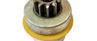
VAZ 2114/2115 cars are equipped with 1.5 cm 3 and 1.6 cm 3 gasoline engines with a distributed injection system. A submersible electric fuel pump is used to supply fuel. It is part of the fuel module installed at the top of the gas tank (under the rear seat). In addition to the pump, the module includes a fuel accumulator (cup), a coarse filter and a fuel level sensor with a float.
To supply fuel in VAZ 2114/2115 cars, a submersible electric fuel pump is used
The VAZ 2114/2115 fuel pump is a conventional DC electric motor in a sealed housing with a one-way valve at the outlet. An impeller of a special shape is located on the electric motor shaft. Its rotation ensures the fuel supply.
Selecting and replacing the fuel pump
Russian car owners prefer BOSH fuel pumps. You should only buy a new pump in specialized stores. The original product must be packaged in thick plastic film filled with special preservative oil. At the same time, a branded BOSH pump cannot cost less than 2 thousand rubles.
Video: how to distinguish an original from a fake
To replace the electric fuel pump on a VAZ 2114/2115 you will need:
- screwdriver with Phillips bit;
- thin slotted screwdriver;
- key or head 7;
- key to 10;
- key to 17.
Video: dismantling the fuel pump
The sequence of actions is as follows:
- Using a 10mm wrench, remove the negative terminal from the battery.
- Open the gas tank cap to reduce the pressure in it.
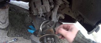
- Remove the rear seat cushion and peel back the carpet and sound insulation.
The fuel module hatch is located under the rear seat
Disconnecting the electrical connector from the fuel module
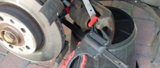
Using a 17 wrench, unscrew the nuts on the fuel pipes
Using a socket 7, unscrew the eight nuts securing the module cover
Symptoms of a problem
A malfunction of the fuel pump of VAZ 2114/2115 cars can be diagnosed by the following symptoms:
- when the ignition is turned on, there is no sound of the pump running;
- the engine does not start or starts with difficulty;
- the power unit is unstable at idle, the speed “floats”;
- “dips” appeared during acceleration;
- the motor has lost power.
The same signs also appear when other elements of the fuel system malfunction.
Before you begin diagnosing or replacing the fuel pump, you should make sure that:
- the fine fuel filter is not clogged (it is changed every 7 thousand kilometers);
- the injectors and fuel pressure regulator are operating normally;
- The sensors for mass air flow, throttle position, and oxygen quantity are working properly.
If the detected malfunction is accompanied by the lighting of the “CHECK” lamp on the dashboard, you should set the error code and decipher it.
Typical malfunctions and their symptoms
VAZ-2114 is a special car, the purchase of which does not require large budgets. Maintenance is also inexpensive for the owner. And even if servicing a foreign car is cheaper, spare parts for a VAZ can be found faster and easier in any store, even in the most remote areas. A common problem in the VAZ-2114 car is the fuel pump. It doesn't pump fuel.
Here, for example, is a typical situation - the engine has stalled. When you try to start the car, it either doesn’t start at all, or it starts and even drives, but after a couple of meters it stalls again. After checking the battery, only the fuel pump remains. Let's look at the most common faults of this unit and find out how to fix the breakdown.
Diagnostics
A malfunction of the VAZ 2114/2115 fuel pump can be caused by:
- malfunctions in the device’s power supply circuit;
- failure of starting and protection elements (relay and fuse);
- wear of electric motor parts.
Checking the electrical circuit
At the beginning of the diagnosis, you should check the electrical circuit of the fuel pump. To do this you will need:
- car tester (multimeter);
- crosshead screwdriver;
- two pieces of wire about 2 m long.
Checking the electrical circuit is carried out in the following order:
- Turn on the ignition without starting the engine. When the key is in the first position, a click should be heard, characteristic of turning on the relay, followed by a slight whirring of the pump electric motor. If there is no click, the relay is faulty or is not receiving power. If there is a click, but no buzzing, the wiring coming from the relay or the pump motor itself is faulty.
- Under the glove compartment, find an additional mounting block consisting of three relays and three fuses. The pump relay is located in the middle, and the fuse is located to the left of it. Remove the fuse from its socket, test it with a multimeter, and if the result is negative, replace it. When replacing the fuse, please note that it is rated for a maximum of 15 A.
The relay and fuse for the fuel pump on the VAZ 2114/2115 are located in the mounting block under the glove compartment.
Set your multimeter to voltmeter mode. Connect one probe of the device to the relay terminal to which the pink wire fits, and the second to the car body. Turn on the ignition. The device should show the on-board network voltage in the range of 11.7–12.4 V. If there is no voltage, the problem may be a broken wiring or a malfunction of the ignition contact group. In this case, it is better to contact an auto electrician. If power is supplied, check that the relay is working. With the ignition on, use a screwdriver or a piece of wire to close the contacts to which the pink and gray wires go. This closes the circuit bypassing the relay. If the fuel pump works, replace the relay.
The ground wires of the fuel pump are attached to the body with a self-tapping screw
Pressure check
If the pump is working properly, but the engine begins to operate intermittently, you should check the fuel pressure in the system. For this you will need:
- pressure gauge (can be a tire gauge with a measurement limit of 5–7 kPa);
- petrol-resistant hose with a diameter of 10–12 mm and a length of 50–80 cm;
- two clamps for a hose of the appropriate diameter;
- Phillips screwdriver;
- nipple cap;
- dry rag.
In addition, the presence of an assistant is desirable.
The verification procedure is as follows:
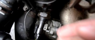
- In the engine compartment on the engine fuel rail, locate the pressure measuring fitting (on the right side).
- Remove the plastic cap (plug) from the fitting.
Find the pressure fitting and remove the cap from it
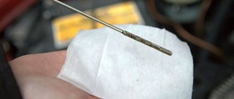
When unscrewing the spool valve, fuel may spray out of the fitting.
Connect the pressure gauge to the fitting using a hose and clamps
Pinout
Knowledge of pinouts may be required if a car enthusiast wants to make an adapter for computer diagnostics with his own hands, or if you need to connect without one. Experts recommend buying ready-made devices without the need to make a plug yourself. However, if you do not have such an opportunity, and diagnostics need to be carried out urgently, we will consider two main pinout options used on VAZ cars of various years of manufacture. Until 2002, AvtoVAZ products used the following pinout option:
- The 4th and 5th pins are GND outputs.
- Pin 16 – +12 V (power line).
- The 7th contact is the diagnostic line itself.
Since 2002, the pinout scheme has changed significantly. Now it looks like this:
- Pin H – +12 V (power line).
- Contact G – +12 V for the fuel pump.
- Pin A – GND output.
- Contact M – diagnostic line.
There is one important note to note regarding this diagram. If you connect the connector without a block, but directly, it is recommended to use the charge from the cigarette lighter as a source of electricity. The peculiarity of this pinout is that contact H is not always routed in the car. The use of G is also not recommended because high frequency current is supplied. This can have a negative impact on the adapter, even to the point of burning it out. However, cases of burning out the fuel pump connector are quite rare. Therefore, if you wish, you can also use this option.
As you can see, the pinout on VAZ cars of different ages is sometimes very different. Therefore, we advise you to look at the registration certificate of your car and find out what year it is made. On older vehicles you will not find the new pinout design as it did not exist yet and on newer vehicles the old design was no longer used.
Pinout of fuel pump VAZ 2107
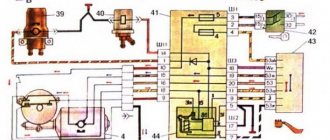
1 – radiator fan drive motor; 2 – mounting block block; 3 — idle speed sensor; 4 – engine ECU; 5 – potentiometer; 6 – set of spark plugs; 7 – ignition control unit; 8 – electronic crankshaft position sensor; 9 – electric fuel pump; 10 – indicator of the number of revolutions; 11 – lamp for monitoring the health of electronic systems and the brake system; 12 – ignition system control relay; 13 – speedometer sensor; 14 – special factory connector for reading errors using the BC; 15 – injector harness; 16 – adsorber solenoid valve; 17, 18, 19,20 – fuse box for repairing the mounting block that protects the injection system circuits; 21 – electronic fuel pump control relay; 22 – electronic relay for controlling the exhaust manifold heating system; 23 – exhaust manifold heating system; 24 – fuse protecting the heater circuit; 25 – electronic air sensor; 26 – coolant temperature control sensor; 27 – electronic air damper sensor; 28 – air temperature sensor; 29 – pressure control sensor and low oil pressure lamp.
You can check the fuel pump on a VAZ 2107 simply by checking the voltage at its connection block with a tester. The presence of voltage will indicate a malfunction of the electric motor. Instead of a tester (multimeter), you can use a test lamp to diagnose a malfunction.
In the absence of one, this can be done by disconnecting the connection block for the fuel pump and fuel level control and applying voltage with wires from the battery to the place where the gray wire is connected +12 and to the place where the black wire is connected - minus. A humming pump will indicate a faulty fuse, power circuit or ECU.
Pinout BN VAZ 2108, 2109, 21099
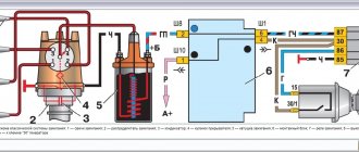
The fuel pump activation relay (2) is shown by an arrow.
1 — nozzles; 2 — spark plugs; 3 — ignition module; 4 — diagnostic block; 5 - controller; 6 — block connected to the instrument panel harness; 7 - main relay; 8 - main relay fuse; 9 — electric fan relay; 10 — controller power supply fuse; 11- electric fuel pump relay; 12 — fuel pump power circuit fuse; 13 — mass air flow sensor; 14 — throttle position sensor; 15 — coolant temperature sensor; 16 — idle speed regulator; 17 — knock sensor; 18 — crankshaft position sensor; 19- oxygen sensor; 20- APS control unit; 21 — APS status indicator; 22 — speed sensor; 23 — electric fuel pump with fuel level sensor; 24 — solenoid valve for purge of the adsorber; 25 — block connected to the ignition system harness; 26 — instrument cluster; 27 — ignition relay; 28 — ignition switch; 29 — mounting block; 30 — electric fan of the cooling system;
A - to terminal “B+” of the generator; B - block connected to block K of the ignition system harness; C - block connected to block L of the ignition system harness; D - wire connected to the interior lamp switch; E - wire connected to the white and black wires disconnected from the interior lamp switch; F - to the “+” terminal of the battery; G1, G2 - grounding points; K - block connected to block B of the front harness; L — block connected to block C of the front harness.
On “nines” with a mechanical fuel pump, the most common malfunction is wear of the fuel pump diaphragm, as a result of which gasoline will leak through the drainage hole in the housing when it operates. The second reason for the failure of such a fuel pump is wear of the pusher, which transmits force from the camshaft cam to the fuel pump drive lever.
Fuel pump pinout
The pinout of the VAZ 2114 fuel pump chip includes contacts for power supply to the electric motor, a fuel level meter contact, and a critical residue alarm contact.
Thus, the pump block chip includes four contacts:
- Remaining indicator:
- Weight;
- Pump power;
- Fuel level.
The power connector located on the block has a pin part - “male”, respectively, the mating part is “female”. It should be borne in mind that the pump unit is not connected to the on-board network directly, but through an adapter harness, one of the terminals of which is connected to the block and the other to the on-board network.
The following wire colors are used in this harness:
- Black and white – mass;
- Gray – supply voltage;
- Pink – level indicator;
- Blue and red – reserve balance.
VAZ 2110 fuel pump pinout
If the fuel pump works directly when connected to the battery, then you will have to ring the wires going from it to the fuel pump relay, and if it does not work, then either replace it with a new one, or you will have to disassemble it and look for a fault inside the fuel pump.
Pinout and where is the diagnostic connector for VAZ-2112
Diagnostics of modern car models is carried out using a special diagnostic connector. It connects to a computer, which analyzes the current state of the vehicle, determines the malfunction and indicates it. If you have the appropriate equipment, you can look for breakdowns even at home. However, not all VAZ-2112 owners can find the diagnostic connector right away. Today we’ll talk about its location on the classic panel and on the Europanel. In which part of the car should I look for the required socket?
Pinout BN VAZ 2113, 2114, 2115
— block headlights; — gearmotors for headlight cleaners*; - fog lights*; — ambient temperature sensor; - sound signals; — engine compartment lamp switch; — electric motor of the engine cooling system fan; — generator; — low oil level indicator sensor; — washer fluid level sensor; — front brake pad wear sensor; — wire tips connected to the common windshield washer pump**; — windshield washer pump; — headlight washer pump*; — wire ends for connecting to the rear window washer pump on VAZ-2113 and VAZ-2114 cars; — low oil pressure indicator sensor; — engine compartment lighting lamp; — wire lug for connecting to the wiring harness of the engine control system; — gear motor for windshield wiper; — starter; — a block connected to the wiring harness of the ignition system on carburetor cars; — coolant temperature indicator sensor; — reversing light switch; — low brake fluid level indicator sensor; - accumulator battery; — low coolant level indicator sensor; — relay for turning on fog lights; - mounting block; — brake light switch; — plug socket for a portable lamp; — hydrocorrector scale illumination lamp; — switch for the parking brake indicator lamp; — block for connecting a backlight lamp; — switch for instrument lighting lamps; - Understeering's shifter; - hazard warning switch; — front seat heating element relay; — ignition switch; — rear fog light circuit fuse; - fuse for the front seat heating elements; — door lock circuit fuse; — front ashtray illumination lamp; — ignition relay; - cigarette lighter; — glove box lighting lamp; — switch for the glove compartment lighting lamp; — heater fan electric motor; — additional resistor for the heater electric motor; — heater fan switch; - heater switch illumination lamp; — lamp for illuminating the heater levers; — gear motors for electric windows of the front doors; — power window switch for the right front door (located in the right door); — gear motors for locking front door locks; — wires for connecting to the right front speaker; — gearmotors for locking rear doors; — wires for connecting to the right rear speaker; — door lock control unit; — wires for connection to radio equipment; — headlight cleaner switch*; — rear window heating element switch; — relay for turning on the rear fog lights; — block for connection to the heating element of the right front seat; — rear fog light switch; — switch for the heating element of the right front seat; — fog light switch*; — switch for external lighting lamps; — left front seat heating element switch; — block for connection to the heating element of the left front seat; — wires for connecting to the left front speaker; — power window switch for the left front door (located in the left door); — power window switch for the right front door (located in the left door); — wires for connecting to the left rear speaker; — side direction indicators; — courtesy light switches on the front door pillars; — courtesy light switches on the rear door pillars; - lampshade; — ceiling lamp for individual interior lighting; — block for connecting to the wiring harness of the electric fuel pump; — trunk light switch; — instrument cluster; — trunk lighting lamp; — display unit of the on-board control system; - trip computer*; — block for connecting the wiring harness of the engine control system; — rear exterior lights; — rear interior lights; — pads for connecting to the rear window heating element; — license plate lights; — additional brake signal located on the spoiler.
Replacing an electric fuel pump on a VAZ
- Reduce pressure in the fuel supply system.
- Using the fuel supply hose tip clamp, disconnect 2 hoses in turn.
- Unscrew the 8 nuts around the circumference of the clamping ring and remove it.
- A wire with negative polarity is attached to one of the nuts; it must be removed carefully.
- We take the electric pump block out of the fuel tank, tilting it slightly, to keep the fuel level indicator sensor lever intact, otherwise it will produce incorrect parameters.
- Remove the sealing rubber ring of the fuel block. If its properties are lost, the product must be replaced.
- Install the pump in reverse order.
When installing fuel hoses, focus on the direction of fuel supply indicated by the arrows, and the installation arrow on the electric pump cover should point towards the rear of the car!
Where is the fuel pump relay located?
Where is the fuel pump relay located? The installation location of the relay varies depending on the make of the car. Most often, it is located under the hood, in the fuse and relay box.
The fuel pump relay is designed in the circuit to prevent accidental application of high voltage to the fuel pump winding. The relay is standard and consists of a plastic body and coils with contacts. It is located in the car interior near the console. To access it, you need to remove the protection cover.
In appearance, it is a small box that resembles a “plug” with an American type of output. Each terminal has a marking that indicates the following: 31 – mass; 30– +12V constant (regardless of ignition); 15– +12 with the ignition on; 50– +12 when the starter is running; TD – signal from the ignition system; TF – engine temperature signal from the injection control unit KE. Outputs: 87 – supplies power to the fuel pump; 87H – oxygen sensor heating; 87V – turns on the starting injector.
But sometimes the fuel pump does not turn on when the key is turned in the ignition. With what it can be connected? First of all, the fuse, although if it had blown, it would not work at all. Maybe the contact is bad?
If the electric fuel pump does not show any signs of life when the ignition is turned on, this does not mean that it has burned out. The cause of the malfunction may also be a relay. The easiest way to test your hearing is that when you turn on the ignition, the relay should click. If you don’t hear a click, there is a high probability that the “relay” is faulty.
It’s easy to check the functionality of the pump itself, so we do this:
- remove the protective casing, under which there is a block with relays and fuses;
- we unscrew the fastenings of the block, remove it, it remains attached to the wires;
- we pull the RB out of the block, place a jumper between two opposite contacts, thus directly supplying power to the BN;
- if with such a connection the electric motor of the pump begins to make noise, it means that the BN itself is working, most likely the fault is hidden in the relay;
- if there is no voltage on any of the contacts on the RB block, you should look for a break in the wiring; there may also be poor contact at the place where the wire is attached to the terminal.
Pinout of diagnostic connectors for VAZ and GAZ cars
Currently, the vast majority of cars have an OBD2 diagnostic connector (trapezoidal 16-pin block, usually located in the steering wheel area). Through this connector you can connect diagnostic equipment to diagnose your car, as well as connect on-board computers and other devices that work through the diagnostic connector.
People often have questions about the pinout of diagnostic blocks for some cars. Our store has various adapters for different models. But if you forgot to order an adapter for your car, you can try to make it yourself, or connect the adapter directly. To do this, we have prepared for you a short review on the pinout of the OBD2 socket, the pinout of the sockets for VAZ and GAZ cars.
OBD2 connector pinout
This option has been common in foreign cars since 2002, and is also installed in all VAZ cars after 2004.
Pin designations: 7 - K-diagnostic line 4/5 - GND protruding contacts 16 - +12V adapter power supply
Pinout of the VAZ block before 2002:
Contact designations: M - k-diagnostic line H or G - adapter power supply +12V
When connecting an adapter without a block directly to the wires, it is better to take power from the cigarette lighter, since the contact shown in Figure H, depending on the model, may not be routed, and when using the G contact, the fuel pump gives very large impulses that can damage the adapter.