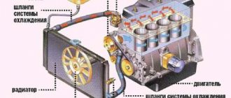
The relay of electric fuel pumps (TN, EBN) for gasoline and diesel controls the power supply to them. If such a controller fails, the engine will not start and will stall. The main aspect of the functioning of the entire power system - its startup - directly depends on the fuel pump auto switch. If the relay works, but intermittently, abnormally, then this is also immediately displayed as the most noticeable problems. The TN relay also provides acceleration for cars with automatic transmission. Let's look at where the fuel pump auto switch is located, how it looks and works, breakdowns and repairs. You will also learn how to check the EBN.2 relay
What is a fuel pump relay, its meaning
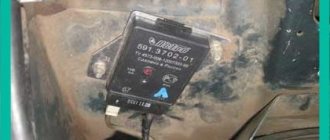
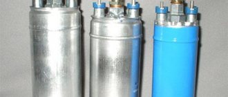
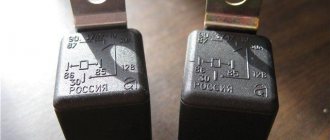
Externally and internally, the fuel pump relay is similar to standard electromechanical releases, since it is the most similar, and sometimes the same part, as in household appliances and other electrical equipment. This is a small square, rectangular (2-3 cm sides) plastic box with 4 (the most common option), 5 flat contacts, reminiscent of a cable plug to an American standard socket. Less commonly, there is a different number of pins (6, 9, and so on) and a different shape (round).
This element closes/unlocks the power contacts of the fuel pump. The extended technical name is electromagnetic (EM) switch. The fuel pump is designated by the abbreviations TN, BN, EBN (electric fuel pump).
Operating principle of the fuel pump relay
The EBN relay itself is a regular EM circuit breaker, but there is also a somewhat complex design if the device controls additional car options. The product does not have sensors inside; it responds only to power, which generates an electromagnetic force that closes the contacts. The device is completely controlled by the vehicle's electronic control unit (ECU), which supplies it with power and commands.
The purpose of EM relays is to switch lines (control, control) of more powerful devices, as well as combine and decompose pulses. The process can be most accurately represented by the “trigger (close) - release (return to initial position)” diagram.
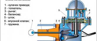
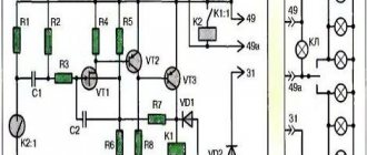
Consider the algorithm according to the figure above:
- The state at zero input is shown. the magnitude of X - current Iin in winding 7.
- When in. the current Iin begins to increase at a specific mark, the armature 10 falls off the stopper 77 and is magnetized to the rod 12.
- As the armature moves, its upper end, transmitting force through the pushing element 9, bends the contact spring 6 upward until its part 8 comes into contact with that 7 of the spring 5, which then extends upward until it stops 4.
- Result: in input. line after completion of the transition gap, current Iout begins to flow from out. Y value.
- With future growth of input. The output current changes are negligible, we can assume that they do not exist.
- When does it come in? the current decreases; at a specific value, the mechanical pressure of the bending springs overcomes the EM force, which attracts the armature to the rod 12.
- The contact elements open, and the output circuit is de-energized. With a subsequent current pulse, the cycle repeats.
The operation algorithm in the car is as follows. After turning the key and starting the ignition, the auto switch starts working, sends a command to the VT and it is activated for 2-3 seconds. To the required pressure on the ramp. Then the device deactivates the pump, and then it starts only when the engine is rotated by the starter or while driving. After stopping the engine, the device turns off the EBN and relieves pressure.
Meaning of contacts
There are different pinouts of the fuel pump auto switch, the most common are 4 and 5 pins, but there are also ones with 7 and 9 or another number of pins - they also control some other options of the car. Each terminal has a marking; it and the circuit are always indicated on the body of the device.
The most popular standard, 4 contacts:
- 30 - general (under voltage);
- 87 (maybe 87a or 88) - for power lines. On foreign circuits - 87a, on Russian ones - 88, the only difference is in the designation;
- 86, 85 - electromagnet winding, for commands from the ECU.
Model with 6 contacts, each signed:
Example of relay contacts with extended functionality:
Example of an EBN auto switch on a Mercedes E (there are 8 pins):
There are also options with unusual digital markings:
We will consider 4-pin types with the usual contact designations, since they are the most popular. There is a basic principle: the conclusions are connected to the lines corresponding to them - information about which of them corresponds to the relay contact is in the technical documentation of the car, the device itself. The diagram is easy to find on the Internet. That is, it will not be difficult to navigate through the different options.
An example of pinout with wire colors (standard colors, but may be different) from the ECU:
So, the conclusions of the 4-pin relay:
- 2 - for power cores;
- 2 - for ECU commands.
Pin 30 is always there; in the deactivated position it is closed to 87a, and when the internal combustion engine starts, it is closed to 87 (if the relay has separate such pins). But in four-contact releases, 2 terminals - 87a, 87 - are connected into one, the auto switch works like a regular EM circuit switch. If the power is removed from the starter, it keeps the contacts closed until the engine stops.
Scheme
Below is a diagram of the fuel pump relay in several versions, showing the terminal connections:
EBN relay functions
The main task is to control the fuel pump. When on ignition - creates pressure in the fuel pipe by activating the fuel pump (BN) for several seconds. After this, the latter will function either with starter cranking or with the internal combustion engine activated.
The working product will still partially activate the VT when the starter is operating, if its control resistor is working properly.
The release may be responsible for some other options, for example:
- heating oxygen sensor. It is triggered on the relay in different ways: on some - directly from the BN, on others - through its own transistor. Outdated auto switches do not have such a detector, but heating is done - operation occurs when the pump starts;
- activation of the starting injector (PF) during a “cold” start. This works as long as the starter does, depending on the t° of the motor. The release operates for a certain period, depending on t°: data about it comes from the KE (injection) control unit to the ECU, and it determines the time. So, at +60 on the engine, the PF starts for a fraction of a second, but at low values it can work for 8–10 seconds. The nozzle has 1, or less often 2, channels: for the flow of the sprayed liquid, or it plus a second one - for supplying a similar substance, steam, gas, which helps the specified process take place. A high-quality unit produces a cone-shaped spray—an even, continuous spray appears.
The latest relay models also offer the following options:
- auxiliary function for accelerating the engine with automatic transmission - additionally includes a pump for delivering an increased volume of fuel;
- slowing down the speed: if on the internal combustion engine they are maximum, then the release temporarily turns off the fuel pump, which normalizes them.
Blocks under the hood
Main unit
It is located on the left side, next to the battery.
Decoding elements
p, blockquote 21,0,0,0,0 —>
| 1 | 100A generator |
| 2 | 50A central locking, hazard warning lights, brake lights, heated rear window, horn, interior lighting, electronic control unit |
| 3 | 30A dimensions, head light - headlights |
| 4 | 20A engine control unit |
| 5 | 30A ignition, engine start |
| 6 | 20A engine cooling fan |
| 7 | electrical wiring connector |
| 8 | heater fan relay |
| 9 | horn relay |
| 10 | 10A interior lamps |
| 11 | 10A audio system - radio |
| 12 | A/C fan relay #2 |
| 13 | A/C compressor relay |
| 14 | fog light relay |
| 15 | fuel pump, fuel pump relay |
| 16 | 15A idle air control, camshaft position sensor |
| 17 | 10A engine control unit |
| 18 | engine cooling radiator fan relay |
| 19 | 10A air conditioner switching on |
| 20 | relay No. 1 fan heat exchanger condenser air conditioning system |
| 21 | 10A engine control unit |
| 22 | 10A A/C compressor clutch |
| 23 | 10A horn |
| 24 | 15A fog light fuse |
| 25 | 10A head light - left headlight |
| 26 | 10A head light - right headlight |
| 27 | 10A fuse for right side light, license plate light |
| 28 | 10A left side light fuse, headlight washer relay |
| 29 | size relay |
| 30 | generator pre-excitation resistor |
| 31 | starter relay |
| 32 | 20A Air Conditioning Condenser Heat Exchanger Fan |
| 33 | 30A power window fuse |
| 34 | 30A ABS system |
| 35 | relay for permanent low beam headlights |
| 36 | fuel pump relay |
| 37 | 30A anti-lock brake system - ABS |
| 38 | diode |
| 39 | diode |
| 40 | 30A heater fan fuse |
Where are the fuel pump relays installed?
There are three main locations where the fuel pump relay is located:
- engine compartment, near the KE block (injection control);
- on VAZs - under the dashboard (bottom left of the panel);
- near the ABS unit.
That is, the device is located either under the hood or under the dashboard, among similar “boxes” on the fuse and relay block. Below is exactly such a unit (injection VAZ cars).
It is the location itself, the seat, among other elements, that may vary; you can find it out from the technical documentation of the car on the Internet.
Blocks in the cabin
Layout diagram
p, blockquote 6,0,1,0,0 —>
- Fuse box
- Relay block
- ETACS module or heated rear window relay
- Rear wiper relay (hatchback)
- Seat Belt Timer (without ETACS)
- Wiper relay (without ETACS)
- Open Door Module (Chime Bell)
Fuse box
It is located on the left pillar under the instrument panel, behind the protective cover.
p, blockquote 11,0,0,0,0 —>
| 1 | 10A Turn signals, reverse switch, gearbox range switch, automatic transmission selector |
| 2 | 10A Instrument Cluster, ETACM, Pre-Excitation Resistor, Seat Belt Warning Timer |
| 3 | 10A Instrument cluster |
| 4 | 15A Airbags |
| 5 | 10A ECM, PCM, automatic transmission selector, transmission range switch, mass air flow sensor, speed sensor, fuel filter lamp |
| 6 | 10A Central locking |
| 7 | 10A Emergency Alarm, ETACM (Time Delay and Alarm Control Module) |
| 8 | 10A Brake light, automatic transmission selector, automatic transmission lock solenoid |
| 9 | 20A Heated rear window |
| 10 | 10A Headlamp assembly, power windows, electric headlight range control, headlight washer, ETACM, front fog lights, air conditioning condenser heat exchanger fan, engine cooling fan, fuel filter relay, rear window washer |
| 11 | 20A Front wiper and washer |
| 12 | 20A Heated seats |
| 13 | 10A ABS - ABS |
| 14 | 10A Clock, audio, automatic transmission selector |
| 15 | 15A Cigarette lighter |
| 16 | 10A Electric mirrors |
| 17 | 10A Heated rear window, heated mirrors |
| 18 | 20A Rear wiper |
Symptoms of TN relay problems
Signs of incorrect operation of the EM relay are as follows:
- no power is supplied to the VT. That is, the car does not start, there is no connection to the power supply of the pump, no fuel is supplied;
- constant hum of the pump, the pump stopped turning off, which it should do after optimal pressure. Excessive fuel consumption appears, the battery runs out;
- there is no characteristic sound effect (the familiar grinding sound) when the ignition is activated;
- the pump operates even after exceeding the highest possible engine speed threshold.
Some internal combustion engines can start with the relay partially working (with malfunctions) - then you can start it with the starter. And also, even if the upper speed limit is exceeded, the BN can be activated, but the start-up is not carried out immediately, the engine stalls while driving, and noise is detected when the pump is running.
Other symptoms are listed in the table:
Testing contact groups
Finally, it wouldn’t hurt to call the contact group. Understanding what a relay is for, it becomes clear that it is an electromechanical switch. When current is applied, it closes two contacts and transmits the current further. It looks like this.
It can be understood that in the open position, when no current is supplied to the relay, the contacts should not short-circuit with each other in principle. When electricity flows in reverse, the pads are connected to each other. This is what the diode continuity reflects.
- Touch the pair with the probes. They need to be installed in the same way as before.
- Without voltage supply, the tester should not make sounds in dialing mode.
- Then apply voltage and look at the device. Firstly, a characteristic loud squeak should appear. Secondly, numbers flash on the screen.
Be aware that beepers may break. Therefore, before ringing the five-pin relay, check them. You can simply touch the tip of the screwdriver with the probes or short-circuit them.
Please note that the instructions are universal for all types of relays: turns, wipers, main unit.
Source
Causes of malfunctions
The EBN relay rarely breaks down; it does not contain particularly sensitive elements. This is largely a fairly stable mechanics, consisting of relatively reliable metal contact parts and an electromagnetic coil. The most common cause of problems is natural wear and tear.
Breakdowns and malfunctions of the fuel pump relay are most often caused by the following factors:
- oxidation, contamination, burnout of contacts and terminals. Oxides and corrosion appear;
- capacitors burned out;
- short circuits;
- blown fuse. Often it fails for the above reason;
- breaks in the electrical circuit (on the wiring leading to the relay);
- marriage;
- incorrect installation of the immobilizer. The anti-theft principle is based on blocking the power supply to the BN, so the problem may lie in the specified element.
How to check the EBN relay
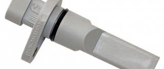
In addition to the EBN circuit breaker itself, you need to check the fuse - it is located on the power line, located in the same block as the relay, but in its own location. Usually enclosed in a plastic box. Its composition is usual - inside the flask there is a sensitive low-fusible plate, a wire, which, when overheated (if there are surges or short circuits), melts and breaks, thus de-energizing the circuit and protecting the equipment. Pictured is Renault Safrane:
It is easy to check a fuse with a glass bulb in microcircuits - just look to see if the wire is broken. But in a car the body of the part is different, which complicates visual control. Therefore, it is advisable to check with a multimeter (by ringing for a break) or with a tester.
The method for checking the fuel pump relay with control is applicable to both it and the fuse. The tester will be a light bulb with a current of up to 0.25 A; a 12 V one will do (these are used to illuminate refrigerator chambers). The power should not be greater, as the control unit may burn out.
It is mounted instead of a relay, its wires are twisted to the power wires and inserted into the terminals in the socket. The ends leading to the light bulb can be soldered directly to the base; you can hold them with your fingers, but it will also be more convenient to buy a small socket, on which the wires are clamped with bolts.
We take out the relay. We connect the wires to ground and 87. When the engine starts, the light should light up and not blink - then the fuse is good. If not, then it is broken or there is a break in the chain. It is easy to dismantle - the plastic box snaps out of its seat. There is also a method with jumpers (discussed below).
Photo with instructions for BMW (also suitable for other models):
However, you can immediately check the fuse with a multimeter for a break, and if one is found, then replace it and see if the VT will work. If not, then that's the problem.
So, the main sign of a breakdown is that there is no buzzing from the pump after turning the ignition key, and the first thing to check is the fuse. For example, on the Lada Kalina and Granata it is on the F21 circuit (15 A), and the relay is K12.
Next, we will describe another algorithm of actions for checking the VT relay on the specified models:
- We activate the ignition.
- We remove the relay.
- We supply +12 V (we use a battery) to pin 11 of the diagnostic block or place a jumper between the terminals in the socket for pins 87 and 30 of the circuit breaker. You can take simple thick copper wires. If the pump is working properly, then it starts to work, the relay should be changed. If there is no start, then, without removing the jumpers, holding one control wire to ground, touch the second wire to the EBN supply wire; if there is no light, then there is a break in the circuit.
- We observe whether there is a buzzing sound from the pump.
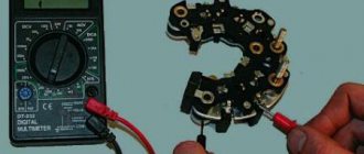
Explanation for the last option from the table: take the relay from its seat, take any 12 V battery or power supply (these are found in household appliances). You can use the same car battery in a car.
Remove the wiring from such a power source and connect it to the output. 85 and 86, multimeter in ohmmeter mode - to 87 and 30.
There is no voltage - a breakdown, if the level of its drop is more than 1 V - the contacts have oxidized. If there is power and the pump does not work, there is a break in the electrical circuit, a broken fuel pump, or a problem with the computer.
We illustrate how to check the fuel pump circuit with a sample:
Diagnostics with a scanner
For diagnostics, you can use a diagnostic device connected to a special socket on the car. The decoding of the code is in the machine manual or on the Internet. But this procedure is somewhat limited, since it does not show whether there is a wire break or whether the fuse is in order, etc. details.
An example of checking the electrical circuit on a VAZ 2110
Let's look at a specific example on a VAZ 2110 of how to check exactly the electrical circuit of the fuel pump connected to the relay and the ECU.
We need to make sure that the VT is working: to do this, we connect the control unit to its connector. Turn on the ignition - the light should light up, if not, the pump is broken. The procedure also checks the relay.
Remove the rear seat and hatch cover. We find a chip with wires for the fuel pump, unfasten it:
We check the power, it is important to connect the wiring correctly. The voltage is measured on the control wires. We hold one control wire to ground, the second one touches the other terminals in turn. Thus, we will check whether power is supplied from the ECU to the relay.
So, if the light does not light up, it is the wiring or relay that is damaged; less often, the reason may be in the computer. If there is light, then the pump is faulty. Let's move on to the relay - it is located near the front passenger seat under the cover into which the legs rest.
We ring the circuit breaker. First, unscrew the mounting bolts (heads 8 and 10). They put a chip on the VT and start the ignition. If the pump works, the relay is fine, but the contact has come loose somewhere. When the pump does not function, you need to check whether there is 12 V going to the connected chip. Remove it from the pump; there are 4 multi-colored wires there. They examine 2 middle ones - gray and black and white, between them there is a potential difference, that is, voltage.
You can also check the EBN directly. You will need any 12 V power source (unit) (no more), you can use the one installed in the car and run wires from it. 12 V is supplied to the middle terminals. If the TN is working properly, a hum will be heard from its operation.
If the described method is inconvenient for the user, you can use another method (we have already mentioned it): between outputs. 87 and 30 put a jumper. When the ignition is activated, the EBN should not start. When it starts, it means there is a problem on the electronic control unit.
Simple method with replacement with a new relay
If there is a new circuit breaker in stock, then simply put it in place of the old one. Further, it is logical that if the problem is not observed, then the problem was in the old part. The product can also be removed from the mounting block for testing; the relay responsible for the power windows is suitable.
What tools will you need?
To check, take a test lamp, the current consumption of which should not exceed 0.25 A. Instead, you can use a multimeter - a device that has the functions of a voltmeter, ammeter and an apparatus for measuring ohmic resistance. To unscrew the relay blocks, you will need wrenches corresponding to the diameter of the bolts.
It is advisable to have a relay diagram, main characteristics and current values with you. As a rule, the necessary data is applied to the device body. Typically, on most models, the connectors are located according to a standard layout. But it’s better to know the exact location so you can check the number of contacts later. The standard relay layout is shown below:
How to access the relay
We remove the armrest in the center and open a segment of the dashboard; a cigarette lighter and ashtray are built into it.
We remove the plastic protection, unscrew the nuts securing the box to the body, take out the block where the relays and fuses are located:
All that remains is to unclip our EM release and insert a new one into the socket.
Repair, replacement
If the external contacts have oxidized (on the assembly itself or in the seat), then they are cleaned, the break in the circuit is corrected by twisting, replacing the wiring, installing a new fuse - perhaps these are all cases when repairs are advisable.
If there is a problem inside the relay, then this usually cannot be repaired - they throw it away and buy a new one. Of course, you can try to open the device and figure out its insides - but the body of the part is sealed, you will need to re-glue it securely. Even if it is possible to repair the internal parts, then, as a rule, the lifespan of a circuit breaker that has survived such intervention may not be long.
Although there are successful cases of repair - see fig. Below is a successful one, but we personally don’t inspire much confidence.
Let us describe the restoration of the Opel Vectra relay. In this case, such a repair is successful and appropriate - all that was required was to solder the legs (the photo shows that the solder has come off).
Installation and selection of relays is simple: take a device for a specific car brand or one with similar parameters, replacement - the old one is removed from its seat and the new one is inserted. We have described the placement locations and an example of how to remove the block from the relay on a VAZ.
You need to understand that we examined the problems of the relay. That is, even if it is working properly, it may be the fuel pump that is broken or its line may be broken. We touched upon some aspects of checking this node quite deeply. The user will be able to test two mechanisms.
Power supply
The main and auxiliary relays make clicks during operation - this indicates its full functionality. The power couple is responsible for this, which also needs to be checked.
One of the contacts is always energized, while the second receives electricity only when it is on.
You can check them using a voltmeter. It is also included in the tester and is designated by the symbol “V”. Set the switch to constant voltage mode.
Now you can proceed to checking:
- All components that receive current from the relay must be disconnected.
- Now find the necessary contact to which current always flows. You can find it through the datasheet.
- Place the right probe on it, and short-circuit the second one to the car body.
If there is voltage, everything is fine and there are no problems. If there is no contact, you will have to change the entire relay, since the part is not repairable.