November 28, 2014 Lada.Online 367 790 16
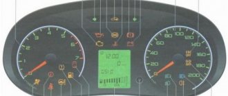
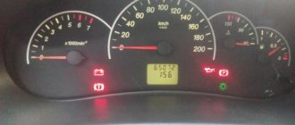
The combination of devices of Lada Granta and Lada Kalina 2nd generation is designed to display driving characteristics, the current state of vehicle systems that ensure traffic safety, as well as the correct operation of the entire vehicle as a whole. Next, we will consider a description of the Lada Granta dashboard, as well as the meaning of instruments and alarms.
Description of the Lada Granta/Kalina 2 panel:
- tachometer , shows the speed of the engine crankshaft, the red scale zone indicates a dangerous operating mode for the engine;
- engine management system malfunction indicator (Check Engine) , turns on orange when the ignition is turned on and goes out after the engine starts, the lamp is lit after starting the engine or while driving indicates the failure of any element of the engine management system (does not mean that the engine should be stopped immediately, however, the cause should be eliminated as soon as possible), the error can be determined using the diagnostic connector;
- left turn signal indicator;
- emergency low oil pressure indicator , turns on in red when the ignition is turned on and goes out after starting the engine, the lamp is lit when the engine is running and a constant (for 5 s) buzzer signal indicates insufficient oil pressure in the system;
- ABS anti-lock braking system status indicator (optional) turns on orange when the ignition is turned on and after 2 seconds. after the engine starts, it goes out; in other cases, the lamp is lit, indicating a system malfunction that should be repaired at a specialized service station;
- immobilizer mode indicator lights up orange and displays the status of the immobilizer and the vehicle security mode;
- The coolant overheat indicator turns on in red when the ignition is turned on and after 5 seconds. after starting the engine it goes out, the sound signal indicates engine overheating (t>115C), the signal will be repeated until the temperature drops below 110C, when the indicator turns on, it is prohibited to operate the car, otherwise it will lead to serious engine damage;
- brake system emergency indicator , turns on red when the ignition is turned on and goes out after the engine is started, the lamp is lit and the buzzer signal (5 lights on) when the engine is running indicates a drop in the brake fluid level below the “MIN” mark in the master cylinder reservoir, operate the car with the light on indicator is prohibited;
- indicator for turning on the right turn signal (with a green filter in the form of an arrow);
- battery charging indicator , turns on in red when the ignition is turned on and goes out after the engine starts, the lamp is lit or glows half-lit while the engine is running indicates a lack of charging current due to a malfunction of the generator or voltage regulator, as well as low voltage (or breakage) of the belt generator drive, operating the vehicle with the indicator on is prohibited;
- speedometer , shows how fast the car is currently moving;
- indicator of the operating mode of the exchange rate stability system (ESC) (in a variant version), turns on yellow when the ignition is turned on and goes out after starting the engine, the lighting of the “ESC OFF” lamp indicates that the system is turned off, and lighting and flashing while driving indicates the activation of the exchange rate control system stability, in other cases the burning of the lamp indicates a system malfunction;
- signaling device prohibiting transition to higher gear “O/D OFF” (not used);
- headlight high beam indicator , indicates that the headlights are on high beam;
- signaling device for turning on the rear fog lights , indicates that the ZPTF is turned on;
- low beam headlight indicator , indicates that the headlights are low beam;
- indicator for turning on the front fog lights , indicates that the PTF is turned on;
- daily mileage counter reset button , by pressing the button, set the daily mileage counter in the liquid crystal display to 0 or select the daily or total mileage display modes;
- liquid crystal display of the on-board computer , displays information from the BC, see description below;
- door open indicator , lights up red if the door is open;
- reserve fuel indicator indicates the need to refuel the vehicle; do not allow the gasoline to run out completely, as this may damage the fuel pump;
- low tire pressure indicator , lights up when tire pressure drops;
- the electric power steering status indicator (connected in a variant), turns on in orange when the ignition is turned on and goes out after the engine is started; the lamp is lit while the engine is running indicates a malfunction of the power steering, which must be eliminated as soon as possible;
- driver's seat belt warning light , lights up when the ignition is turned on if the seat belt is not fastened;
- power unit fault indicator (not used);
- Airbag status indicator turns on in orange when the ignition is turned on and goes out after the engine starts; in other cases, the lamp is lit indicating a system malfunction; you must contact service as soon as possible, because In addition to failure in an emergency, the airbag may unexpectedly inflate.
Installation of the dashboard Kalina 1
Installation is done in reverse order. For prevention, all surfaces are cleaned of dust and dirt, checked for defects and damage. The rag is dry; moisture may get on the surface of the electrical connector. Before installing a new instrument panel, check the correct location of the fastening units.
Installation steps:
- Install the plug connecting to the car's electrical network.
- Turn on the battery and check the operation of the dashboard.
- Disconnect the battery.
- Insert the lower rollers into the mounting recesses.
- Fix the shield, tighten 2 screws.
- Install the cover plate into the lower latches and screw in the mounting screws.
Several types of instrument panels have been developed for the Lada Kalina. They differ in appearance and functionality, but their installation diagram is the same.
When connecting the plug, you need to carefully move the latch to the “closed” position. This part is made of thin plastic and may break if pressed hard. First, insert the plug tightly, then turn the latch.
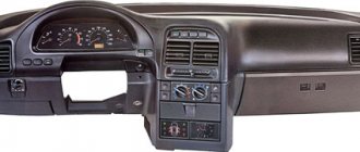
How to remove the center console in a luxury package
Let's say it was decided to dismantle the panels located on the center console. You can see that there are two of them. One is the front panel of the air conditioner, the second protects the radio and contains air duct grilles in its design. These two parts are not connected to each other. However, it will not be possible to remove the radio panel unless you first remove the climate control panel. Below it are metric screws (A, B) that secure the media center shield from below.
New Lada: Dismantling and assembling the gearbox | VAZ | VAZ management
Central console of Kalina-2, Luxury package
Correct installation of the Kalina 2 dashboard
Mount the instrument panel according to the standard scheme. First, clean the parts from dust and clogging. Check the integrity of the housing and replace the light bulbs if necessary. The temperature in the cabin should not fall below +15°C. In winter, it is recommended to carry out work in a heated garage or similar room.
Installation of the instrument panel:
- Connect the electrical connector and battery.
- Check the operation of the instrument module.
- Disconnect the battery.
- Screw the shield with 4 bolts.
- Install the decorative panel and secure it with 2 screws.
- Replace the protective plug or fuse box cover.
Detailed electrical diagrams of car components
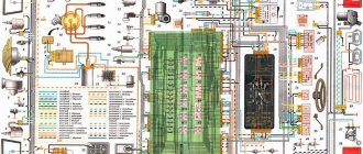
Instrument panel wiring harness wiring diagram
1,2,3,4 blocks of the instrument panel wiring harness to the rear wiring harness blocks; 5,6 blocks of the instrument panel wiring harness to the blocks of the front wiring harness; 7 block of the instrument panel wiring harness to the block of the wiring harness of the air supply box; 8 block of the instrument panel wiring harness to the block of the front wiring harness; 9 lighting control module; 10 ignition switch; 11 on-board computer mode switch; 12 windshield wiper switch; 13 horn switch; 14 light signaling switch; 15 instrument cluster; 16 evaporator temperature sensor; 17 interior air temperature sensor; 18 air conditioner switch; 19 controller of the automatic climate control system; 20 heater damper gearmotor; 21 rear window heating switches; 22 alarm switch; 23 brake signal switch; 24 cigarette lighter; 25 electric power steering control unit; 26,27 connectors for the instrument panel wiring harness to the radio; 28 backlight lamp for the heater control panel; 29 lighting Lada Kalina; 30 mounting block: K3 additional starter relay; K4 additional relay; K5 relay breaker for direction indicators and hazard warning lights; K6 wiper relay; K7 relay for high beam headlights; K8 horn relay; K9 relay for turning on fog lights; K10 relay for turning on the heated rear window; K11 electric seat heating relay; K12 air conditioning compressor clutch activation relay; 31 heater motor switch; 32 electric heater motor; 33 additional resistance of the heater electric motor; 34 glove box lighting; 35 glove box lighting switch; 36 control unit of the automobile anti-theft system APS6; 37 driver airbag module; 38 passenger airbag module; 39,40 the instrument panel wiring harness blocks to the ignition system wiring harness blocks.
Electrical connection diagram for the wiring harness of the ignition system Lada Kalina 11174, 11184, 11194
1 oil pressure warning light sensor; 2 coolant temperature indicator sensor; 3 additional fuse box; 4 fuses for the electric fan of the engine cooling system; 5 electric fuel pump relays; 6 relays for the electric fan of the engine cooling system; 7 ignition relay; 8 relays 2 of the electric fan of the engine cooling system; 9 relay 3 of the electric fan of the engine cooling system; 10 electric fan of the engine cooling system; 11 throttle position sensor; 12 idle speed controller; 13 coolant temperature sensor; 14 diagnostic block; 15 ignition system harness block to the instrument panel harness block; 16 solenoid valve for purge the adsorber; 17 speed sensor; 18 ignition system harness block to instrument panel harness block 2; 19 mass air flow sensor; 20 crankshaft position sensor; 21 oxygen sensors; 22 controller; 23 rough road sensor; 24 diagnostic oxygen sensor; 25 ignition coil harness block to the ignition system harness block; 26 ignition coils; 27 ignition system harness block to ignition coil harness block; 28 spark plugs; 29 nozzles; 30 resistor; 31 air conditioning pressure sensors; 32 blocks of the ignition system harness and injector wiring harness; 33 phase sensor; 34 knock sensor.
Electrical connection diagram of the front VAZ-11184 wiring harness
1 headlight right; 2 right fog lamp; 3 speed sensor right front; 4 speed sensor left front; 5 air temperature sensor; 6 VAZ starter; 7 rechargeable battery; 8 generator; 9 blocks of the battery and starter harness and the front harness; 10 ABS hydraulic unit; 11 reverse light switch; 12 reverse lock; 13, 14, 15, 16 blocks of the front wiring harness to the blocks of the instrument panel wiring harness; 17 front wiring harness block to rear wiring harness block; 18 left headlight 11184; 19 left fog lamp; 20 electric washer motor; 21 beeps; 22 air conditioning compressor; 23 air conditioning fan electric motor.
Electrical connection diagram for rear wiring harness VAZ-11184
1 - 4 rear wiring harness blocks to the instrument panel wiring harness blocks; 5 rear wiring harness block to front wiring harness block; 6 side direction indicator, right; 7 left side direction indicator; 8 handbrake sensor; 9 blocks of the rear wiring harness to the rear right loudspeaker; 10 interior lamp; 11 reverse lock switch; 12 trunk light; 13 additional brake signal; 14 electric fuel pump module; 15 right lamp; 16 blocks of the rear wiring harness to the rear left loudspeaker; 17 rear window heating element; 18 rear wiring harness block to additional wiring harness block 3 (trunk lid); 19 rear wiring harness block to additional wiring harness block 2 (left rear door); 20 block of the rear wiring harness to the block of the additional wiring harness (right rear door); 21 left lamp 11184; 22 electrical package controller; 23 block of the rear wiring harness to the block of the rear additional wiring harness (left front door); 24 rear wiring harness block to rear additional wiring harness block 2 (right front door); 25 airbag control unit; 26 driver's seat belt pretensioner; 27 passenger seat belt pretensioner; 28 interior air temperature sensor; 29 right rear speed sensor; 30 left rear speed sensor; 31 electric heater for the right seat; 32 right seat electric heater switch; 33 left seat electric heater switch; 34 electric heater of the left seat.
Diagram of electrical connections of the additional rear wiring harness (tailgate wiring harness) and the wiring harness of the license plate lights of the LADA KALINA 11174 car.
1 rear window wiper motor; 2 additional brake signal; 3, 4 blocks of the rear wiring harness, additional to the blocks of the rear wiring harness; 5 block to the trunk lock electric motor; 6 trunk lock; 7 rear window heating element; 8 block of the rear wiring harness, additional to the block of the wiring harness of the license plate lights; 9 block of the wiring harness for the license plate lights to the block of the rear additional wiring harness; 10, 11 license plate lights.
Electrical connection diagram for rear wiring harness VAZ-11174
1 - 4 rear wiring harness blocks to the instrument panel wiring harness blocks; 5 rear wiring harness block to front wiring harness block; 6 side direction indicator, right; 7 left side direction indicator; 8 handbrake sensor; 9 blocks of the rear wiring harness to the rear right loudspeaker; 10 interior lamp; 11 reverse lock switch; 12 trunk light; 13 block of the rear wiring harness to the block of the additional wiring harness; 14 electric fuel pump module; 15 right lamp VAZ-1174; 16 blocks of the rear wiring harness to the rear left loudspeaker; 17 rear wiring harness block to additional wiring harness block 3; 18 rear wiring harness block to additional wiring harness block 2 (left rear door); 19 block of the rear wiring harness to the block of the additional wiring harness (right rear door); 20 left lamp; 21 electrical package controllers; 22 block of the rear wiring harness to the block of the rear additional wiring harness (left front door); 23 rear wiring harness block to rear additional wiring harness block 2 (right front door); 24 airbag control unit; 25 driver's seat belt pretensioner; 26 passenger seat belt pretensioner; 27 interior air temperature sensor; 28 right rear speed sensor; 29 left rear speed sensor 1174; 30 electric heater of the right seat; 31 right seat electric heater switch; 32 left seat electric heater switch; 33 electric heater of the left seat.
Electrical connection diagram of the front VAZ-11174 wiring harness
1 headlight right; 2 right fog lamp; 3 speed sensor right front; 4 speed sensor left front; 5 air temperature sensor; 6 starter VAZ-1174; 7 rechargeable battery; 8 generator; 9 blocks of the battery and starter harness and the front harness; 10 ABS hydraulic unit; 11 reverse light switch; 12 reverse lock; 13, 14, 15, 16 blocks of the front wiring harness to the blocks of the instrument panel wiring harness; 17 front wiring harness block to rear wiring harness block; 18 left headlight Lada Kalina; 19 left fog lamp; 20 electric washer motor; 21 beeps; 22 compressor; 23 air conditioning fan electric motor; 24 rear window washer motor.
Electrical connection diagram for rear wiring harness VAZ-11194
1 - 4 rear wiring harness blocks to the instrument panel wiring harness blocks; 5 rear wiring harness block to front wiring harness block; 6 side direction indicator, right; 7 left side direction indicator; 8 hand brake sensor Lada Kalina; 9 block of the rear wiring harness to the block of the additional wiring harness; 10 interior lamp; 11 reverse lock switch; 12 trunk light; 13 electric fuel pump module; 14 right lamp VAZ; 15 rear wiring harness block to additional wiring harness block 3 (trunk lid); 16 rear wiring harness block to additional wiring harness block 2 (left rear door); 17 block of the rear wiring harness to the block of the additional wiring harness (right rear door); 18 left lamp 1194; 19 electrical package controller; 20 block of the rear wiring harness to the block of the rear additional wiring harness (left front door); 21 rear wiring harness block to rear additional wiring harness block 2 (right front door); 22 airbag control unit; 23 driver's seat belt pretensioner; 24 passenger seat belt pretensioner; 25 interior air temperature sensor; 26 speed sensor right rear; 27 left rear speed sensor; 28 electric heater of the right seat; 29 right seat electric heater switch; 30 left seat electric heater switch; 31 left seat electric heater.
Wiring diagram for fog lights
1 - fuse in the assembly block; 2 — immobilizer output; 4 — rear fog lights; 4 — external optics control unit; 5 — ignition switch; A - to power supplies.
The procedure for removing the instrument panel on Lada Kalina 2
The dismantling steps for Lada Kalina 2 differ from the first model. The reason is that engineers increased the number of attachment points, which reduced the “rattling” effect after long-term use. Correct replacement of the dashboard is carried out in compliance with standard conditions: heated interior, lighting, disconnected battery.
How to remove the panel on Lada Kalina 2:
- Removing the protective plug located in the lower left part; it is secured with latches. In early models, it is necessary to unscrew the screws to completely remove the fuse box cover.
- Unscrew the 2 screws of the decorative trim and dismantle it.
- Remove 4 bolts on the dashboard (2 each on the bottom and side).
- Tilt the shield, disconnect the connector by turning the lock.
- Remove the panel.
To remove plastic parts, you can use a set of polymer pullers. It will also be needed to replace moldings, clips, and decorative overlays.
After dismantling, the on-board computer readings are reset to factory settings, with the exception of mileage. If the machine is used for personal purposes, you can reconfigure the system yourself. In company vehicles, it is recommended to record the data before starting work. They may be needed to check the condition of the machine.
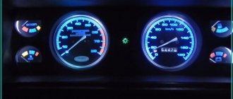
Replacing LEDs
Having disassembled the instrument panel unit, you will notice that the illumination of two scales and the display is provided by flat LEDs. They, in turn, can be replaced with parts of the same standard size. But remember one rule: the switching polarity cannot be violated. On a planar diode, polarity is indicated by the presence of a “bevel” on one side.
There is an example when standard elements were replaced with blue light diodes:
The next video will show how you can further improve the tidy by simply replacing the LEDs.
The operating voltage of one diode is 3-3.5 Volts. Do not install elements designed for other voltages. It is not recommended to use LEDs that are too powerful and consume significant current.
Adding a digital scale
For those who have experience working with plastic, the following tuning option is recommended.
In the instrument panel, under any of the two scales, you can cut out a window in which a standard indicator is fixed. We are talking about a digital indicator consisting of two or three separate segments.
The plane of the tidy is cut through, an indicator is attached to the window
When the modification is completed, the dashboard looks like this:
3-segment indicator installed and secured
If there are glares, use a simple solution: cover the inside of the glass with a matte tint film. Good luck.
Why you should know the pinout
But before you start this kind of upgrade, you need to understand which wire leads where. The pinout of the instrument panel of a VAZ-2110 car is a very important point when “tuning”. Without this, you risk simply getting confused in a fairly large number of wires, buttons and various sensors. The pinout will be useful in any case - both when making minor improvements and when completely replacing the instrument panel.
The process of installation and dismantling itself is quite labor-intensive, but if you know the correct sequence of actions, then there is nothing particularly difficult about it.
For these works you will need a minimum set of tools - a screwdriver and pliers.
For those who are doing this for the first time, it is best to stock up on self-adhesive pieces of paper, like those on which prices are written in stores, and a pen. With their help, at the time of disassembly, you will indicate, firstly, the sequence of dismantling the parts, and secondly, which wire is connected where. At first glance, this may seem time-consuming, but in fact, for beginners, such markings will help them put the panel back together faster.
At the same time, before starting work, it is best to stock up on a pinout diagram - at least conditional. After all, during the work process you need not to confuse anything and correctly understand each wire and connection during the reassembly process. It is worth noting one very important point. By and large, understanding the pinout of the panel of the “tenth” family will not be difficult even for a beginner.
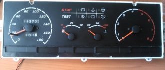
But you need to remember that there are certain differences here, depending on the plant where the car was manufactured and the year of its manufacture. For example, the instrument panel may be an old model, with a mechanical odometer. If the odometer is electronic, then this is a newer version. Accordingly, there are certain differences in pinout between these panels.
conclusions
After reading the information given in the article, it will be easier for you to navigate behind the wheel and control the operation of the Lada Kalina car systems.
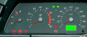
The instrument panel serves to inform the driver about all important processes occurring in his car. It is by using the scales, indicators, symbols and lamps located on this device that the person sitting behind the wheel is able to monitor the performance of components and systems. For the shield to function correctly as a single system, it requires regular diagnostics. It consists not only of scanning by connecting electronic reading devices to the computer, but also by visually monitoring the performance of all specified components of the dashboard (lamps, etc.).
So that the owner of the Lada Kalina, namely the instrument panel of this model we will talk about today, can easily navigate this complex device, the manufacturer kindly agreed to complete the car with the appropriate instructions. It is enough to familiarize yourself with its postulates and all the secrets of the dashboard will be revealed to you, then the instrument panel will not seem like something incredibly complicated.
The manufacturer did his best when developing the design of such a thing as the instrument panel on the Lada Kalina car. It is unlikely that you will be able to find owners dissatisfied with the “interface” of the device. The dashboard is painfully informative and primitive in terms of perceiving symbols and managing some of them.