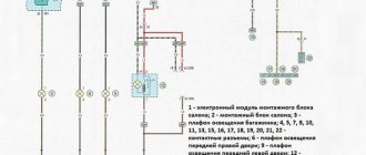
1ABS electronic control unit2Air conditioning control unit -in the heater control panel3Air conditioning control unit (rear) -in the heater control panel4Antenna unit -if equipped5Side impact sensor, driver's side6Side impact sensor, rear left7Side impact sensor, passenger side8Side impact sensor, rear right9Anti-theft system control unit10Sound anti-theft signal - intake system resonator 11 Audio output amplifier - under the front right seat - if equipped 12 Additional battery 1 - under the front left seat - if equipped 13 Additional battery 2 (van) - in the kitchen cabinet 14 Auxiliary heater control unit (Air Top 3500) - under the underbody , on the right - if equipped15Additional heater control unit (Thermo Top) - under the body, on the left - if equipped16Battery17Camping equipment control unit (caravan)18Diagnostic connector (DLC)19Diagnostic unit - instrument panel20Driver door electrical control unit21Left rear door electrical control unit (with sliding power door) - left pillar 22 Passenger door electrical control unit 23 Right rear door electrical control unit (with power sliding door) - right pillar "0" 24 ESP stability control unit (includes acceleration sensor, lateral movement sensor) 25 Mechanism control unit Roof Lift & (Van)26Electronic Engine Control Module - Near Fuse/Relay Box in Engine Compartment 127Cooling Fan Motor Control Module 1 - Suspension (Front Left)28Cooling Fan Motor Control Module 2 - in Cooling Fan Motor 2 - If Installed29Unit Fuse/Relay Box, Engine Compartment 130Fuse/Relay Box, Engine Compartment 231Fuse/Relay Box, Engine Compartment 332Fuse/Relay Box, Instrument Panel 1 - Center Dashboard 33Fuse/Relay Box 2, Instrument Panel - Under Fuse/Relay Box 1, Instrument Panel 34 Fuse Block /relay, instrument panel 3 - behind fuse/relay block, instrument panel 1/235Fuse/relay block, instrument panel 4 - behind fuse/relay block, instrument panel 1/236Fuse/relay block, left seat - under seat 37Auxiliary fuse 1 (switch differential lock, rear 10A) - left front pillar38Additional fuse 2 (additional heater 30A) - under the left seat39Additional fuse 3 (door electrical control unit, left rear 40A) - under the left seat (some models)40Resistor 1 of the heater fan motor - near the fan motor rear heater 41 Resistor 2 of the heater fan motor - near the rear heater fan motor - if equipped 42 Sound signal 143 Sound signal 2 - if equipped 44 Immobilizer control unit - instrument cluster 45 Immobilizer ring antenna - near the ignition switch 46 Instrument cluster control unit - dashboard 47 Telephone control unit - behind the glove compartment 48 Multifunction nal control unit 1 - functions : Automatic transmission (automatic transmission), charging system (with additional battery), cruise control, door/hood switch contact recognition, electrical load control, power windows, fuel pump, headlight washers, door mirror defogger, rear defroster windows, hazard warning lights, windshield defroster, horn, turn signals, instrument cluster lights, interior lamps, automatic wipers, reversing lights, starter, sunroof, light switch, windshield washer, windshield wiper49Multifunction control unit 2 - functions: Anti-theft system, central locking, electric door mirrors, electric sliding door, electric windows, sunroof50Navigation system control unit - in the navigation system display51Ambient air temperature sensor52Parking system control unit53Driver seat heating control unit54Passenger seat heating control unit55Steering wheel position sensor - if equipped 56 Electric sunroof control unit 57 SRS electronic control unit 58 Rear door opening/closing drive control unit - left "D" pillar - if equipped 59 Traffic information system control unit - under the instrument panel 60 Traffic information system control unit (alternative position) - under the instrument panel 61 Transfer case control unit (with 4WD) - rear final drive62Electronic transmission control unit (automatic transmission) - near the engine control unit63Voice synthesizer - under the front right seat - if equipped64Vehicle speed sensor - gearbox (some models)
Fuses and relays Volkswagen Transporter T5 & | Base-ex 19:58, 16 September 2018
Volkswagen
Author: admin
Comments are closed.
It contains up to 24 fuses and almost as many relays, depending on the equipment.
Conveyor T5 launch -9
So, if any voltage-powered device in your car has failed, then first of all you need to check the operation and condition of the fuse. Model T5 As mentioned above, the T5 minibus model is equipped with several control devices for electrical appliances.
Up. Volkswagen Transporter Long Busik › Logbook › Fuse diagrams for T5 GP. Comrade...
The list of fuses is on the back of the unit cover. Poll Have you ever replaced fuses yourself? Relays can switch high currents over a distance, thereby allowing the use of weak control switches and wiring.
Some relays can operate on a timer, such as intermittent wipers or a heated windshield. And then, not in all cases.
Unlike mechanical switches, relays can be controlled by more than one signal.
Volkswagen T5 Comfort block
Some relays can operate on a timer, such as intermittent wipers or a heated windshield. If a fault is detected in a circuit equipped with a relay, you should always remember that the problem may lie in the relay.
The test can be done by replacing it with a known good relay. To replace the relay, remove it from the socket and insert a new one.
Where are they located?
Every Volkswagen Transporter owner has faced this question. If you have recently acquired this machine, we will help you solve this problem. Volkswagen Transporter T4 and T5 vehicles have different fuse blocks.
Volkswagen Transporter T5
The main power supply with fuses and relays in the T4 Transporter is located inside the vehicle. Many car owners encounter a problem at first glance. Its location is not highlighted in any way, so motorists will need to consult their owner's manual to identify it. But it's not that difficult. The power supply is located on the left under the steering wheel. It is hidden behind a protective plastic strip that must be opened to access the device.
As for the T5 model, here the developers have implemented several power supplies. One of them is located in the car's interior, the other in the engine compartment. Finding these power supplies is not difficult: one of them is located in the middle of the dashboard, and the other is in the battery compartment in the engine compartment.
Emergency procedures for VW T5 Transporter. Replacing fuses VW T5 Transporter
7. Replacing fuses
Circuit breakers
Due to the fact that the car is constantly being improved and the purpose of fuses is constantly changing, it is impossible to provide a reliable specification of fuses in this section. The location of the fuses can be obtained from a Volkswagen Commercial Vehicles Dealership.
One fuse can protect the circuits of several electrical consumers. And vice versa: one consumer can have several fuses. Replace fuses only after eliminating the cause of their blown.
If the new fuse quickly blows again, have the relevant electrical equipment checked by a workshop.
WARNING The vehicle's electrical system contains high voltage and can cause electric shock, severe burns or death! Do not touch the ignition system wires under any circumstances.
Avoid short circuits in electrical equipment.
WARNING Using improper fuses, repaired blown fuses, or shorting unfused electrical circuits can cause fire and serious injury. Never install fuses with a higher current rating than required.
Replace blown fuses only with fuses of the same rating (color and markings must be identical) and size. Repaired fuses (so-called
"bugs") do not use!
It is prohibited to replace fuses with pieces of wire, paper clips and other improvised means!
Note To avoid damage to the electrical system in the car, before replacing the fuse, be sure to turn off the ignition, lighting (headlights, interior lighting, etc.) and all electrical devices and remove the key from the ignition switch.
Using high amperage fuses may cause damage elsewhere in the arterial circuit.
Protect exposed fuse boxes from dirt and moisture.
Dirt and moisture in the fuse box can cause damage to electrical equipment.
One electrical appliance may have several fuses. One fuse can protect the circuits of several electrical consumers.
Front panel fuses
Opening the fuse panel in the front panel (Multivan)
– Open the bottle holder in the front panel. – Squeeze both levers on the back of the bottle holder and remove the bottle holder.
– Insert a flat object, such as a screwdriver from an on-board tool, onto the top edge of the transparent cover and carefully lift the cover.
Opening the fuse panel in the front panel (Transporter)
– Press the recess under the drink holder and remove the lid towards the rear. Note The fuse box cover must be removed and installed correctly, being careful not to damage the vehicle.
Protect exposed fuse boxes from dirt and moisture. Dirt and moisture in the fuse box can cause damage to electrical equipment. There are other fuses in the vehicle that are not mentioned in this section. They can only be replaced at a service station.
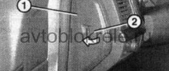
Fuses in the engine compartment
Opening the fuse box in the engine compartment
– Open the hood. – If necessary, remove the battery cover located on the rack. To do this, turn the quick release locks 90°. – Remove the partition (1) by moving it upwards. – Turn both quick release locks by 90°.
– Grasp the fuse box cover from the front and fold it up.
Closing the fuse panel in the engine compartment
– Close the fuse box cover and turn both quick release locks. – Insert the partition. At the same time, make sure that both recesses of the partition simultaneously cover the fuse cover jumper and the vertical partition jumper.
Replacing blown fuses
Replacing Volkswagen Transporter T5 and T4 fuses yourself
Every Volkswagen Transporter owner has faced this question. If you have recently acquired this machine, we will help you solve this problem. Volkswagen Transporter T4 and T5 vehicles have different fuse blocks. Volkswagen Transporter T5
Main power supply with fuses and relays in the vehicle. The T4 conveyor is located inside the vehicle. Many car owners encounter a problem at first glance.
Its location is not highlighted in any way, so motorists will need to consult their owner's manual to identify it. But it's not that difficult. The power supply is located on the left under the steering wheel.
it is hidden behind a protective plastic strip that must be opened to access the device.
As for the T5 model, here the developers have implemented several power supplies. One of them is located in the car's interior, the other in the engine compartment. Finding these power supplies is not difficult: one of them is located in the middle of the dashboard, and the other is in the battery compartment in the engine compartment.
Scheme
We consider separately the removal of a position and the description of the elements of each model.
Replacing fuses in Volkswagen Transporter T5
Information about the purpose, as well as the fuse diagram for the Volkswagen Transporter T5 is located on the back of the block cover. There are also tweezers located there, with which you can replace the defective part.
On one's own
Let's look at the replacement procedure inside the car.
First, you need to use the T5 Conveyor fuse diagram to determine the location of the required insert. The work procedure is as follows:
- Remove the desired insert from the circuit board using tweezers and check it with a tester.
- If the part is burnt out, replace the insert with another one of the same rating. They are painted the same color, for example, a 10 A fuse is red.
- Close the lid and check the operation of the unit.
If the insert burns out again, it is necessary to repair this device. There is no point in changing the fuse again. You cannot install a part with a high rating; the system being tested may fail.
Model t4
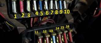
Location of power components in Volkswagen T4
| Serial number | What is he responsible for? |
| one | Provides low beam operation and changes the range parameters of the left headlight. |
| 2 | it is also responsible for the operation of the flashlight bulbs and is designed to adjust the range parameters of only the right headlight. |
| 3 | This fuse box is responsible for the operation of the instrument panel and license plate LED lights. |
| 4 | Without this part, the wipers will not work. |
| 5 | Provides operation of wipers, as well as windshield and rear window washers. |
| 6 | Responsible for the performance of the heating and air conditioning systems of the engine. |
| 7, 8 | Provides operation of side lights, as well as left and right brake lights. |
| nine | The operation is carried out by a device designed to heat the rear window and side mirrors. |
| 10 | Responsible for the operation of fog lights. |
| 11, 12 | Without these fuses, the high beams will not work. In addition, the high beam warning lamp will stop working. |
| 13 | Without this part, the horn will not work. In addition, the radiator fan will also stop working. |
| 14 | This element performs several functions at once:
|
| fifteen | Ensures the functionality of the minibus engine electronics. |
| sixteen | This number allows you to turn on LED instrument panel lighting and glove box lighting. |
| 17 | This element ensures the operation of the direction indicators. |
| 18 | Part No. 18 provides:
|
| 19 | Without this part, the operation of the radiator fan and the air conditioning system, that is, the air conditioner, is impossible. |
| 20 | If this part fails, the brake light bulbs will not work and neither will the speed control sensor. |
| 21 | Ensures the functioning of light bulbs in the interior of the minibus, as well as in the trunk. In addition, this part is responsible for the operation of the interior clock, central locking and radio. |
| 22 | Ensures the functionality of the cigarette lighter. |
This was a straightforward description of the fuse box. They are arranged in a row at the bottom of the diagram. Now let's talk about the purpose of the relay. Components that are not used will not be described in the table.
| Number | Description |
| one | This relay ensures the operation of the air conditioning compressor. |
| 2 | Rear window wiper, as well as its washing machine. |
| 3 | Injection and ignition system. If a component fails, the engine will not be able to start. |
| 4 | This relay reduces the load on terminal X of the ignition switch. |
| 6 | Device for interrupting direction indicators and light signals. |
| 7 | Headlight washer motor. |
| eight | Without it, the windshield washer mechanism will not work. |
| nine | Responsible for the functionality of the mechanism that warns the driver about unfastened seat belts. |
| 10 | Ensures the functionality of the fog lamp bridge. |
| eleven | Without this component the horn will not work. |
| 12 | Responsible for the operation of the diesel pump and system heating device before starting the engine. |
| 13 | Ensures the operation of preheater and starter blocking devices. |
| 14,16 | These components allow the ABS system to function. |
| fifteen | If any element is broken, the ABS hydraulic pump will not work. |
| 17 | The ABS valves and pump will stop working if component #17 fails. |
| 18 | Electric adjustment mechanism for the front seats. |
| 20 | Responsible for the performance of the starter, as well as the reversing lights. |
| 21 years old | Lambda probe heating device. |
In addition, there is an additional relay in the engine compartment. In particular, an element of the heating system of a diesel internal combustion engine is located on the partition above the brake booster.
Removal and replacement procedure
Any Transporter minibus car owner will sooner or later be faced with the need to replace fuses. Actually, like the owner of any other car. No one is immune from this, so in any case, replacing fuses in a motorist’s everyday life is inevitable. To learn how this process works, we provide you with detailed instructions for replacing components.
So, if a voltage-powered device in your car fails, first of all you need to check the serviceability and condition of the fuse.
And rightly so, because you won't buy a new fuel pump if you just need to replace a fuse. For this you will need a screwdriver. And not in all cases.
In some car models, the power supply is hidden behind a plastic plug that is secured with screws, but is usually held in place only by a latch.
All work on replacing parts of the power supply must be carried out with the battery turned off to avoid short circuits:
- Open the hood and remove the negative terminal from the battery.
- you need to decide on which power supply you need to replace the components to fix the problem. In any case, open the desired lock and, guided by the diagrams above or the markings on the back of the power supply, find the faulty element.
- You will find special tweezers in the power supply housing. It is intended directly for disassembling fuses. Disassemble the burnt component and inspect it. If its body is slightly burnt or the fuse wire in the part itself is already broken, then it must be urgently replaced. It will be more difficult with a relay - it is almost impossible to visually determine its malfunction. Only occasionally do the bayonets of the relay, which is connected to the socket, burn slightly. But without ringing the relay and disassembling it, it is unlikely that it will be possible to determine the condition. Therefore, if you have a fault with the relay and you do not have devices to check it, you need to act with blows. That is, disassemble the suspicious relay and put a new one in its place, and then check the functionality of the devices.
- After replacing the part, check if everything is now working properly. If so, close the lid and pedal for fun. If the problem persists, we recommend taking your minibus to an electrician to have him call the entire circuit.
Arrangement of elements in a car
Manufacturers of the VAG concern strive to saturate each of their models with complex devices and systems to the limit. This VW model – Transporter T5 – was no exception. Control units are located in different places on the machine and are responsible for the operation of a particular unit. Protects their operation from overload in the vehicle network, short circuit, Volkswagen T5 fuse blocks.
They are located in the engine compartment and in the cabin. The circuit boards with parts are arranged in such a way that it is convenient for the vehicle owner to find them, check them and, if necessary, replace a blown Volkswagen T5 fuse.
Depending on the complexity of the device, one block may have one or more inserts. Another picture is also possible when one fuse is responsible for the operation of several devices.
It should be noted that in different years of production on some modifications of cars, VW T5 fuses could have different purposes. We will talk about the arrangement of blocks on the 2013 restyled model, which corresponds to many versions of the T5 commercial vehicle.
Fuse diagram for Volkswagen Transporter T5
Scheme
Let's consider the layout and description of the elements of each model separately.
Model T5
As mentioned above, the T5 minibus model is equipped with several control devices for electrical appliances. One of them is in the engine compartment. Its location and purpose of components are described below.
The fuse box is located in the engine compartment next to the battery
Description of the block parts located in the engine compartment
Description of the block parts located in the engine compartment
Below is a diagram of the unit located inside the car in the center console area, as well as a table describing its components.
Block with elements located in the center of the console in the cockpit
Descriptive table of the power supply, which is located inside the minibus
Descriptive table of the power supply, which is located inside the minibus
In addition, some modifications of Volkswagen T5 minibuses are equipped with another device. The relay block is located on the instrument panel immediately behind the power supply. Below you will find its diagram and description.
Diagram of a relay device located behind the power supply on the instrument panel
High power fuse diagram Volkswagen Transporter T5
Description
| one | (175 / 225A) Generator |
| 2 | (125A) Battery power distribution, auxiliary ignition relay, driver door control module, passenger door control module, rear window defroster, terminal X relay, individual fuses |
| 3 | (50A / 100A) Charging system (with additional battery), rear left power door control unit (some models), rear right power door control unit (some models), charging system divider relay (with additional battery) |
| 4 | (125A) Battery power distribution (70A) Positive connection in engine compartment wiring |
| 5 | (50 A) Battery power distribution (some models), separate fuses |
| 6 | (60A) Glow plug relay (50A) Exhaust air pump motor |
| 7 | (70/80/100A) Cooling fan motor(s) |
| eight | (40/50/100A) Cooling Fan Motor(s), Separate Fuses |
| nine | (100A) Battery power distribution, ignition switch |
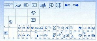
Location of control units
Description
| 1 | ABS electronic control unit |
| 2 | Air conditioning controller - in the heater control panel |
| 3 | Air conditioning control unit (rear) - in the heater control panel |
| 4 | Antenna unit - if equipped |
| 5 | Driver side impact sensor |
| 6 | Side impact sensor, rear left |
| 7 | Side impact sensor, passenger side |
| 8 | Side impact sensor, rear right |
| 9 | Anti-theft control unit |
| 10 | Security Alarm - Intake System Resonator |
| 11 | Audio Output Amplifier - Under Right Front Seat - If Equipped |
| 12 | Auxiliary Battery 1 - Under Left Front Seat - If Equipped |
| 13 | Additional battery 2 (RV) - in the kitchen cabinet |
| 14 | Auxiliary heater control unit (Air Top 3500) - under the body, on the right side - if equipped |
| 15 | Auxiliary heater control unit (Thermo Tor) - under body, left - if equipped |
| 16 | Accumulator battery |
| 17 | Camping Equipment (RV) Control Unit |
| 18 | Diagnostic connector (DLC) |
| 19 | Diagnostic unit - instrument panel |
| 20 | Driver door controller |
| 21 | Rear Left Door Controller (Power Sliding Doors) - Left Pillar |
| 22 | Passenger's door control unit |
| 23 | Rear Right Door Wiring Control Module (Power Sliding Door) - Right Pillar |
| 24 | ESP stability control unit (includes acceleration sensor, lateral movement sensor) |
| 25 | Roof lift control unit (RV) |
| 26 | ECM - Near engine relay/fuse box 1 |
| 27 | Cooling Fan Motor Control Module 1 - Suspension (Front Left) |
| 28 | Cooling Fan Motor 2 Controller - On Cooling Fan Motor 2 - If Installed |
| 29 | Fuse and relay box, engine compartment 1 |
| 30 | Fuse and relay box in engine compartment 2 |
| 31 | Fuse and relay box in engine compartment Z |
| 32 | Fuse/Relay Box, Instrument Panel 1 - Center of Instrument Panel |
| 33 | 2 Fuse and Relay Box, Instrument Panel - Under Dashboard Fuse and Relay Box 1 |
| 34 | Fuse/Relay Box, Instrument Cluster 3 - Behind Fuse/Relay Box, Instrument Cluster 1/2 |
| 35 | Fuse/Relay Box, Instrument Panel 4 - Behind Fuse/Relay Box, Instrument Panel 1/2 |
| 36 | Fuse/Relay Box, Left Seat - Under Seat |
| 37 | Additional fuse 1 (rear differential lock switch 10A) - front left pillar |
| 38 | Additional fuse 2 (additional heater 30A) - under the left seat |
| 39 | Additional fuse 3 (rear left door electronics control unit 40A) - under the left seat (some models) |
| 40 | Heater Blower Motor Resistor 1 - Near the rear defroster blower motor |
| 41 | Heater Blower Motor Resistor 2 - Near Rear Heater Blower Motor - If Equipped |
| 42 | Beep 1 |
| 43 | Beep 2 - if present |
| 44 | Immobilizer control unit - instrument cluster |
| 45 | Immobilizer ring antenna - on ignition switch |
| 46 | Instrument cluster control unit - instrument panel |
| 47 | Telephone exchange - behind the glove compartment |
| 48 | Multifunction control unit 1 - functions: automatic transmission (automatic transmission), charging system (with additional battery), cruise control, door/hood switch contact recognition, electrical load control, power windows, fuel pump, headlight washers, heated mirrors rear view, rear light view, rear window defroster, hazard lights, windshield defroster, horn, turn signals, instrument cluster lights, interior lamps, auto wipers, reverse lights, starter, sunroof, light switch, windshield washer, wiper |
| 49 | Multifunction control unit 2 - functions: anti-theft system, central locking, electric door mirrors, electric sliding doors, electric windows, sunroof |
| 50 | Navigation control unit - on the navigation display |
| 51 | Ambient temperature sensor |
| 52 | Parking system control unit |
| 53 | Driver seat heating control unit |
| 54 | Passenger seat heating control unit |
| 55 | Steering Wheel Position Sensor - If Equipped |
| 56 | Electric sunroof control unit |
| 57 | Electronic control unit SRS |
| 58 | Rear Door Open/Close Control - Left "D" Pillar - If Equipped |
| 59 | Traffic information control unit - under the instrument panel |
| 60 | Traffic information control unit (alternate position) - under the instrument panel |
| 61 | Transfer case control unit (4WD) - rear final drive |
| 62 | Electronic transmission control unit (ATM) - on the engine control unit |
| 63 | Voice synthesizer - under right front seat - if equipped |
| 64 | Vehicle Speed Sensor - Transmission (Some Models) |
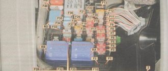
Blocks in the cabin
Main unit
Photo - an example of the entire block
Upper section diagram
Designation
- 5A - 10-pin header / 6-pin header
- 3A - 10-pin connector
- 5/15A – 10-pin connector or alarm data recorder
- 15A - 10 pin connector
- 5A - 10-pin connector
- 25A - 6-pin connector
- 15/30 - 12V socket, voltage converter
- 20 / 25A - Heater control unit (heater)
- 25 / 30A – Supply fan
- 15 / 30A – Air conditioning
- 15A - Cigarette lighter
- 5A - 10-pin header / 6-pin header
- Local relay
- Local relay
- Local relay
- 30A - on-board charger
- 30A - Roof hydraulic unit
- 10A - Light ceiling lamps
- 10A - Refrigerator compartment
- 5A - Water pump
- 5A - Control panel for van equipment
- 15A - 12V socket
- 15A - 12V socket
- 10A - Roof fan or 12V socket
- 15A - Trailer recognition control unit
- 20A - Trailer recognition control unit
- 20A - Trailer recognition control unit
- 7.5A - Trailer recognition control unit
- To book
- 5A - Voice amplifier control unit
- To book
- To book
- 15A - Driver's seat lumbar support
- 40A - Right sliding door control unit
- 80A — Control unit for recharging the second battery
- 40A - Left sliding door control unit
- 40A — Supply fan
- 6-pin connector
- To book
Diagram, location and purpose of power supply and relays
In universal Volkswagen Transporter cars, there are many configurations that differ in electrical wiring. Therefore, the Volkswagen Transporter utility bus has several fuse mounting blocks.
The main unit on the T4 model is located on the lower left side of the instrument panel. In addition to it, there are two more expansion units in the dashboard - the first for 15 fuse links, and the second for five relays. These two blocks are installed above and below the main group of fuse links. In the center of the instrument panel there is a fourth mounting block, which contains only the relays. On the floor of the body under the driver's seat there is a niche for an additional battery; it contains a fifth block with a relay.
The author of the video, Dmitry Maysakov, will talk about the Volkswagen T5 comfort unit in the video.
High-rated fuses are installed in the engine compartment, which are responsible for the operation of the power unit. These fuses are placed directly on the battery.
In addition, there are separate fuses installed in the following locations:
- fuse for the standard radio (from 5 to 10 A), installed on the back of the unit;
- 10 A fuse link on navigation system (optional).
The location of the fuse boxes on T4 cars produced from 1990-2003, whether gasoline engines or diesel engines, has not changed. But the purpose of the fuses is slightly different on buses before restyling (1996) and after.
The T5 transporter began production in 2003 and has two fuse blocks installed on the left side of the engine compartment, two fuse and relay blocks in the central part of the dashboard, and an additional block under the front left seat. The location of the blocks in the car did not change until the model was discontinued in 2015.
T4 mounting blocks
Installation diagrams for fuses and relays, as well as their purpose, will be considered using the example of a 2002 Volkswagen Transporter T4 in the maximum possible configurations.
Blocks in the dashboard
The main unit is closed with a hinged plastic cover located to the left and below the steering column. The block has space for 12 relays, in fact there are fewer of them installed.
–
T4 main unit wiring diagram
Identification of fuses in them.
| Position | Purpose |
| A | Switching on the rear heating and ventilation system (optional) |
| B | Windshield wiper and rear window fluid supply system |
| IN | Engine control units |
| G | Additional elements of the ignition system |
| D | Reserve |
| E | Emergency stop indication |
| AND | Headlight glass washer |
| Z | Main wiper (windshield) |
| AND | Sound reminder about lighting elements that are not turned off |
| TO | Power supply to fog lights |
| L | Warning signal |
| M | Supplying power to the fuel pump |
Under the two rows of relays there are 22 fuses of various ratings to protect electrical equipment. A description of the purpose of these inserts can be found in the table.
| Position | Denomination, A | Chain |
| PR01 | 10 | Powering the low beam filament of the left headlight and adjusting the angle |
| PR02 | 10 | Same for the right headlight |
| PR03 | 10 | Rear registration plate and visor lights |
| PR04 | 15 | Rear window cleaning system |
| PR05 | 15 (20) | Windshield cleaning system (in case of optional heated injectors, the rating increases) |
| PR06 | 30 (20) | Microclimate system fan. Depending on the year of manufacture of the car, the denomination may be different. |
| PR07 | 10 | Side lights on the starboard side |
| PR08 | 10 | Likewise, only for the left side |
| PR09 | Reserve | Reserve |
| PR10 | 15 | Fog lights (front and rear) |
| PR11 | 10 | High beam thread on the left |
| PR12 | 10 | Same for the right side |
| PR13 | 10 | Warning signal |
| PR14 | 10 | Depending on the configuration - ABS system, automatic transmission control unit, central locking, electric windows and mirrors |
| PR15 | 10 | Engine control unit, speed detection and maintenance systems |
| PR16 | 15 | Lamps on the instrument cluster, glove box lighting, direction indicators |
| PR17 | 10 | Additional heater (optional) |
| PR18 | 20 | Engine and fuel pump operation system |
| PR19 | 10 | Cooling system control units (fans and additional pumps) |
| PR20 | 10 | Brake lights |
| PR21 | 15 | Radio and acoustics, diagnostic system, lighting |
| PR22 | 15 (10) | Cigarette lighter operation. Denomination may vary |
Under the main block there is an additional panel for 16 inserts of optional equipment.
– Additional block T4
The purpose of the fuses is in it.
| Number | Denomination, A | Protected area |
| PR01 | 15 | Socket for additional equipment |
| PR02 | 15 | Trailer lighting |
| PR03 | 10 | Minibus sliding roof drive |
| PR04 | 20 (3) | Optional additional heater. In cars of different years, there may be a telephone in this place |
| PR05 | 10 | ABS system |
| PR06 | 3 (10) | Built-in telephone control unit. On later cars, this insert protects the ceiling light circuit |
| PR07 | 15 | Equipping a car for a taxi or an additional searchlight |
| PR08 | 10 | Additional roof fan |
| PR09 | 15 (25) | Radio, instrument cluster functions. On later cars - a two-tone signal |
| PR10 | 15 | Locking the locks |
| PR11 | 15 | Front seat heating system |
| PR12 | 30 | Electrically heated mirrors and rear window systems |
| PR13 | 3 (30) | Second telephone block. On later versions - climate control system |
| PR14 | 30 | Climate control system (rear cabin) |
| PR15 | 20 | Optional auxiliary heater |
Another block with the following relays is attached above the main unit:
- 1 — activation of the additional coolant pump (A);
- 2 — idle speed maintenance systems (B);
- 3 — turning on glow plugs for diesel (B);
- 4 - additional elements of the ignition system, not available on all gasoline engines (G);
- 5 - similar, but for cars with air conditioning (D).
– Relay socket on the left side of the panel
In addition to the relay, there are three fuses - one 30 A for the window drive system and two 15 A, which protect the engine control unit.
There is an additional relay block in the central part of the instrument panel.
– Relay in the central part
The purpose of the parts is described in the table.
| Position | Purpose |
| A | Reserve |
| B | All-wheel drive connection block |
| IN | Activating the reverse warning lights |
| G | 150-amp generator circuit (automatic transmission) |
| D | 150 Amp Generator Circuit |
| E | Air intake mode switch for microclimate system |
| AND | Coolant supply to the additional interior heater |
| Z | Automatic climate control |
| AND | Rear heater fan |
| TO | Phone Speaker Mode Switch |
| L | Auxiliary heater control |
Under the seat
There is a small relay box under the driver's seat.
– Placement of elements under the seat
The block contains two relays:
- connecting the second battery (A);
- ensuring the operation of the second heater (B).
Under the hood
There is a block installed under the hood, the diagram of which is shown in the photo.
– Engine compartment block T4
The purpose of the fuses in it.
| Number | Denomination, A | Protected circuit |
| PR01 | 60 (50) | Heat of air heating plugs |
| PR02 | 50 | First cooling fan motor |
| PR03 | 50 | Similar to the second |
| PR04 | 50 | ABS system (unit itself) |
| PR05 | 110 | Generator protection (optional rated 150 and 175 A) |
| PR06 | 30 | Stability control |
| PR07 | 30 | Additional ESP block |
| PR08 | 5 | Stability control unit |
The author of the video, Dmitry Maznitsyn, disassembles the fuse box. This video shows the design of this unit well.
T5 mounting blocks
The electrical system of the next generation of Volkswagen Transporter T5 cars is much more complex and varied.
Motor block
In the engine compartment (the unit is designated in the diagrams as SA) on the restyled T5 2013, fuses are installed that are responsible for charging the batteries and distributing current from it.
– Main fuse block T5
Purpose of inserts in this block.
| Number | Denomination, A | Protected circuit |
| PR01 | 175 (225) | Generator |
| PR02 | 125 | Battery power supply separator |
| PR03 | 50 and 100 | Double, designed to ensure operation and charging of a second battery |
| PR04 | 70 | Engine compartment circuit distribution |
| PR05 | 50 | Anti-lock braking system |
| PR06 | 60 and 50 | Glow plug system and air pump |
| PR07 | 100 | Cooling fan control |
| PR08 | 40, 50 and 100 | Power distributor |
| PR09 | 100 | Likewise |
| PR10 | Reserve | Reserve |
A large fuse box is installed on the left side of the engine compartment (indicated as SD on the car diagram).
– Block under the hood T5
It has inserts installed.
| Number | Denomination, A | Protected circuit |
| PR01 | 5 | Cooling fan start control |
| PR02 | 5 | Activation circuit for the additional electric pump in the cooling system |
| PR03 | 5 | Heated crankcase ventilation system |
| PR04 | Reserve | Reserve |
| PR05 | 15 | DSG transmission controls |
| PR06 | 30 | ABS control module |
| PR07 | 7,5 | Window washer pumps (only used since 2010) |
| PR08 | Reserve | Reserve |
| PR09 | 5 | Engine control system |
| PR10 | 5 (15) | Evaporative emission control valve (boost limiter) |
| PR11 | 30 | Headlight control |
| PR12 | 10 | Fuel pressure control system |
| PR13 | 10 | Left xenon lamp ignition unit |
| PR14 | 5 | Fuel pump control |
| PR15 | 10 | Reverse lamp activation |
| PR16 | 5 | Brake signals and air flow calculation system |
| PR17 | 5 | Activation keys for ESP and tire pressure checking systems |
| PR18 | 5 | Electric power steering system |
| PR19 | 5 | Clutch pedal limit switch |
| PR20 | 5 | Engine control system |
| PR21 | 5 | Exhaust gas recirculation system |
| PR22 | 10 | Ensuring the operation of injectors |
| PR23 | 10 | Right ignition unit for xenon lamps |
| PR24 | 5 | DSG transmission component control system |
| PR25 | 30 | Engine control units and ignition system |
| PR26 | 5 | Lamps in the right headlight |
| PR27 | 10 | Coolant pump after engine stop |
| PR28 | 10 | Audible warning signal (high tone) |
| PR29 | 5 | Lamps in the right headlight |
| PR30 | 20 | Fuel supply systems |
| PR31 | 15 | Heated lambda probes |
| PR32 | 5 (30) | Fuel pump relay or engine management system |
| PR33 | 5 | Controlling the activation of glow plugs and an additional coolant pump |
| PR34 | 5 | Managing network settings |
| PR35 | Reserve | Reserve |
| PR36 | 30 | Locking the starter when the engine is running |
The Avto-Blogger channel will tell you why fuses are needed in a car and how to check them with a multimeter. ru.
Since May 2011, the purpose of the inserts in the block has changed slightly. Changed items are listed below.
| Number | Denomination, A | Protected circuit |
| PR04 | 30 | Voltage stabilization system and radio (navigation) |
| PR10 | 5 (10 or 15) | Evaporative emission control valve (boost limiter). May have different denominations |
| PR13 | Reserve | Reserve |
| PR23 | Reserve | Reserve |
| PR25 | 30 (20) | Engine control units and ignition system. Variable valve timing system |
| PR26 | Reserve | Reserve |
| PR29 | Reserve | Reserve |
| PR35 | 5 (15) | Fuel pressure limiting system or battery monitoring unit |
| PR36 | 30 (5) | Starter interlock or diagnostic system |
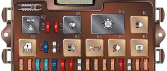
Salon block
In the central part of the interior instrument panel there are two identical fuse blocks (SC at the bottom and SB at the top). Rate assignments may differ on cars produced before May 2004 and after. The next change in the location of the inserts occurred in May 2011 during the release of the restyled T5 model.
– General view of the section of the T5 cabin unit (the second part is identical)
Option for placing fuses in the upper section until May 2004.
| Number | Denomination, A | Purpose |
| PR01 | 30 | Microclimate system |
| PR02 | 5 | Steering angle control system |
| PR03 | 10 | Multi-function block circuit |
| PR04 | 10 | Headlight range control |
| PR05 | 15 | Lamps in the left headlight |
| PR06 | 15 | Likewise |
| PR07 | 15 | Interior lighting |
| PR08 | 5 | Machine electrical diagnostics |
| PR09 | 15 | Brake light limit switch |
| PR10 | 5 | Window cleaning control |
| PR11 | 5 | Illuminated buttons on the panel |
| PR12 | 15 | Cigarette lighter |
| PR13 | 5 | Turning off the brake lights |
| PR14 | 30 | Additional heater |
| PR15 | 7,5 | Air conditioner control |
| PR16 | 5 | Multi-function block circuit |
| PR17 | 5 | Turning on the fog lights |
| PR18 | 5 | Instrument cluster |
| PR19 | 5 | Radio tape recorder |
| PR20 | 5 | Dimensions on the left side |
| PR21 | 5 | Dimensions on the starboard side |
| PR22 | 10 | Diagnostic system |
| PR23 | 25 | Trailer electrical |
| PR24 | 5 | Steering wheel rotation sensor |
| PR25 | 5 | Turning on the air conditioner |
| PR26 | 5 | Differential lock |
| PR27 | 15 | Lamps in the right headlight |
| PR28 | 15 | Likewise |
| PR29 | Reserve | Reserve |
| PR30 | 10 | Injector heating and rear window cleaning |
| PR31 | 30 | Warning signal |
| PR32 | 25 | Cleaning the windshield |
| PR33 | 15 | Navigation |
| PR34 | 25 | Automatic transmission control |
| PR35 | 5 | Instrument lighting |
| PR36 | 25 | Direction indicators |
The Auto Electrician HF channel will tell you how to check the functionality of the fuse.
Designation of the second (lower) part of the block.
| Number | Denomination, A | Purpose |
| PR01 | 15 | Accessory socket 1 |
| PR02 | 5 | Standard anti-theft system |
| PR03 | 5 | Additional climate control fan |
| PR04 | 15 | Accessory socket 2 |
| PR05 | 15 | Accessory socket 3 |
| PR06 | 5 | Oil level checking system |
| PR07 | 10 | Fan on roof panel |
| PR08 | 5 | Parktronic |
| PR09 | 5 | Steering Column Control |
| PR10 | 30 | Radio tape recorder |
| PR11 | 20 | Electric door sliding |
| PR12 | 5 | Additional heater |
| PR13 | 5 | Steering wheel buttons |
| PR14 | 5 | Telephony |
| PR15 | 5 | Automatic transmission control units |
| PR16 | 5 | Radio and navigation |
| PR17 | 5 | Turning on the air conditioning system |
| PR18 | 5 | Likewise |
| PR19 | 5 | Dimming rear view mirror |
| PR20 | 10 | Heated mirrors |
| PR21 | 5 | Standard anti-theft system |
| PR22 | 5 | Turning on the air conditioning system |
| PR23 | 5 | Additional heater |
| PR24 | 5 | Camping systems |
| PR25 | 15 | Heated seats |
| PR26 | 10 | Tachograph |
| PR27 | 15 | Fog lights |
| PR28 | 5 | Door mirror adjuster |
| PR29 | 25 | Additional heater |
| PR30 | 5 | Likewise |
| PR31 | 25 | Sliding sunroof |
| PR32 | 20 | Headlight washer system |
| PR33 | 5 | Tachograph |
| PR34 | 20 | Additional vacuum pump |
| PR35 | 10 | Multi-function block circuit |
| PR36 | 15 | Additional equipment at the rear |
Since June 2004, this block has changed slightly. The table shows only the changed positions of the upper part of the block.
| Number | Denomination, A | Purpose |
| PR01 | 25 (30) | Microclimate system |
| PR10 | 10 | Window cleaning control |
| PR11 | 5 | License plate light |
| PR13 | 5 | Airbag control |
| PR22 | 10 | Diagnostic system, passenger airbag deactivation |
| PR23 | 5 | Starter relay (for manual transmission) |
| PR26 | 30 | Turning off the headlights |
| PR29 | 5 | Tailgate open alarm |
The lower section has changed more.
| Number | Denomination, A | Purpose |
| PR01 | 25 | Trailer electrical equipment |
| PR04 | 10 | All-wheel drive transfer case control |
| PR05 | 10 | Optional equipment |
| PR12 | 5 (10) | Disabling the brake light |
| PR17 | 7,5 | Interior lighting |
| PR18 | 5 | Air conditioning system |
| PR24 | 7,5 | Interior lighting |
| PR25 | 15 (25) | Heated seats |
| PR34 | 15 | Accessory socket 1 |
| PR36 | 5 | Additional camping equipment |
Relay box under the hood
A relay block is installed in the engine compartment. There are two different types of this node.
-Block of the first type -Block of the second type
The purpose of the relay can be clarified in the table.
| Type 1 | Type 2 | Purpose |
| A | A | Manual air conditioner control |
| B | B | Fuel pump circuit activation |
| IN | IN | Turning on the air purge pump |
| G | G | Ignition circuit |
| D | D | Fuel pump circuit activation |
| E | E | Automatic air conditioning control |
| AND | — | Automatic transmission control |
| AND | Reserve | Power steering |
| Z | Z | Additional coolant pump |
| — | AND | Starter activation |
Block under the seat
Another block is located under the seat and can be found in four versions. The diagram is shown in the photo.
– First block type
Arrangement of elements in a block.
| Number | Denomination, A | Description |
| A | — | Control relay for operation of the second battery |
| B-Z | Reserve | Reserve |
| PR01 | 40 | Electrical circuits in the right sliding door |
| PR02 | 25 | Additional heater electrical systems |
| PR03 | 40 | Electrical circuits in the left sliding door |
| PR04 | 5 | Antenna |
| PR05 | 80 | Second battery charging relay |
The block diagram of the second type is shown in the photo.
– Second type
Decoding the elements in the block.
| Number | Denomination, A | Description |
| A and B | Reserve | Reserve |
| IN | — | Control relay for operation of the second battery |
| G and D | — | Special equipment |
| PR01 | 5 | Camping systems management |
| PR02 | 10 | Accessory power socket |
| PR03 | 5 | Tank water pump (camping) |
| PR04 | 10 | Illumination lamps |
| PR05 | 30 | Additional camping equipment |
| PR06 | 40 | Roof lift drive |
| PR07 | 5 | Antenna |
| PR08 | 25 | Additional heater electrical systems |
| PR09 | 30 | Automatic operation of the microclimate system |
| PR010-12 | Reserve | Reserve |
| PR013 | 40 | Electrical circuits in the right sliding door |
| PR014 | 80 | Second battery charging relay |
The diagram of the third type of block can be seen in the photo.
– Third block type
Purpose of parts in this block.
| Number | Denomination | Description |
| A and B | Reserve | Reserve |
| IN | — | Control relay for operation of the second battery |
| Ms. | Reserve | Reserve |
| PR01 | 5 | Antenna |
| PR02 | 25 | Additional heater electrical systems |
| PR03 | 10 | Automatic operation of the microclimate system |
| PR04-6 | Reserve | Reserve |
| PR07 | 40 | Electrical circuits in the right sliding door |
| PR08 | 80 | Second battery charging relay |
Scheme of the fourth type of block.
– Fourth option
The purpose of the fuses in it.
| Number | Denomination | Description |
| A | Reserve | Reserve |
| B | — | Control relay for operation of the second battery |
| V-D | — | Special equipment |
| PR01 | 15 | Circuit 1 for accessories |
| PR02 | 15 | Circuit 2 for accessories |
| PR03 | 15 | Circuit 3 for additional equipment |
| PR04 | 15 | Chain 4 for accessories |
| PR05 | 5 | Antenna |
| PR06 | 25 | Additional heater electrical systems |
| PR07 | 30 | Automatic operation of the microclimate system |
| PR08-10 | Reserve | Reserve |
| PR011 | 40 | Electrical circuits in the right sliding door |
| PR012 | 80 | Second battery charging relay |
Since 2009, this block has become much more complex.
– Block on T5 GP
It includes the following components.
| Number | Denomination, A | Purpose |
| PR01 | 5 | External socket or additional equipment (vehicles for special services) |
| PR02 | 3 | Likewise |
| PR03 | 15 (5) | Likewise |
| PR04 | 15 | Likewise |
| PR05 | 5 | Likewise |
| PR06 | 25 | Likewise |
| PR07 | 15 (30) | Internal socket or 220 Volt inverter |
| PR08 | 20 (25) | Additional heater electrical systems |
| PR09 | 25 (30) | Fan for supplying outside air to the rear of the cabin |
| PR10 | 15 (30) | Autonomous temperature maintenance (the second rating has been installed since the summer of 2010) |
| PR11 | 15 | Cigarette lighter |
| PR12 | 5 | External socket or additional equipment (vehicles for special services) |
| PR13-15 | Reserve | Reserve |
| PR16 | 30 | On-board charger |
| PR17 | 30 | Hydraulic roof drives |
| PR18 | 10 | Interior and kitchen lamps (camper) |
| PR19 | 10 | Fridge |
| PR20 | 5 | Water tank pump |
| PR21 | 5 | Camper equipment management |
| PR22 | 15 | Socket 1 |
| PR23 | 15 | Socket 2 |
| PR24 | 10 (15) | Cargo compartment fan or power outlet 3 |
| PR25 | 15 | Trailer equipment |
| PR26 | 20 | Trailer equipment |
| PR27 | 20 | Trailer equipment |
| PR28 | 7,5 | Rear view camera |
| PR29 | Reserve | Reserve |
| PR30 | 5 | Amplifier (until May 2010, then reserve) |
| PR31 | Reserve | Reserve |
| PR32 | Reserve | Reserve |
| PR33 | 15 | Driver's seat lumbar support |
| PR34 | 40 | Electrical circuits in the right sliding door |
| PR35 | 80 | Second battery charging relay |
| PR36 | 40 | Electrical circuits in the left sliding door |
| PR37 | 40 | Additional supply fan |
| PR38 | 40 | External socket or additional equipment (vehicles for special services) |
| PR39 | Reserve | Reserve |
Removal and replacement process
Required tools: flat screwdriver, keys 10, 14.
Engine compartment
The procedure is as follows:
- Remove the negative terminal after turning off the ignition.
- While pressing the latches, remove the top cover from the unit.
- Remove the broken fuse or relay. If the power multi-function fuse at the end has blown, unscrew the nuts with a 14mm wrench, remove the wires from the studs and, pressing the plastic clips, pull out the part. Completely replaced.
- Install a new element, having first eliminated the source of the short circuit.