Standard fuses for the Opel Astra G are presented in the car in the form of two separate blocks. The modules are located in convenient places for easy access. On cars such as station wagon, hatchback or sedan, the panels are no different. The internal layout and arrangement of parts remains identical. It is necessary to highlight the specific design of the engine compartment. Here the main panel is divided into two areas - safety and relay. This is done to make it easier to identify and replace nodes.
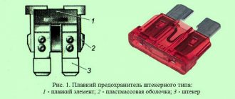
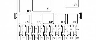
Interpretation of Astra G fuse and relay block diagrams
The full location of the inserts can be found in the service book or on the back of the protective cover of the unit. There is no table describing each element separately.
Cars produced before the millennium are becoming increasingly rare in Russia; the following list was prepared using the example of a 2003 car.
Relay switch part:
| Serial number | Description |
| 1 | Empty |
| 2 | Horn relay switch |
| 3 | Power switch for high beam head optics |
| 4 | Rear windshield wiper switch |
| 5 | Heated rear view mirrors |
| 6/7 | Power supply for front and rear PTFs, respectively |
| 8/9 | Turn signal switches are also activated when the hazard lights are turned on |
| 10 | Telephone audio transmitter |
| 11 | Wheel speed sensor converter relay |
| 12 | Windshield wiper drive |
| 13 | Interior lighting |
| 14 | Rear window heating power line |
| 15 | Comfort unit control unit |
Below are the fuses themselves:
| Number | Description |
| 1 | Reserve |
| 2 | Heated seats and interior heating system |
| 3 | Heated rear window |
| 4/5 | Empty |
| 6 | The low beam of the head optics on the starboard side is also responsible for the headlight range control. |
| 7 | Front side lights, license plate light on the right side |
| 8 | High beam on the right side of the car |
| 9 | Drive for windshield washer pump for optical instruments. |
| 10 | Klaxon |
| 11 | Central lock power supply |
| 12 | PTF |
| 13 | Instrument console display |
| 14 | The wiper drive is also responsible for the sunroof |
| 15 | Drive windows, sunroof, rear-view mirrors, interior lighting, immobilizer |
| 16 | Aft fog |
| 17 | Window drive |
| 18 | Headlight range control and left license plate lamp |
| 19 | Multimedia |
| 20 | Rear window drives |
| 21 | Ignition lock valve with key inserted (for automatic transmission) |
| 22 | Turn signals, emergency lights, indicators - part of the controls and switches |
| 23 | ABS and power steering |
| 24 | Low beam left headlight and corrector |
| 25 | Left side of front and rear dimensions |
| 26 | Left side of high beam head optics |
| 27 | Electric folding roof for convertibles |
| 28 | Interior lighting |
| 29 | Electronic control system for automatic transmission, turn signals and emergency lights |
| 30 | Roof hatch, if the unit is missing, the slot is empty. |
| 31 | Semi-automatic drive of the folding roof |
| 32 | Immobilizer and daytime running lights. |
| 33 | Terminal 30 of the tow hitch |
| 34 | Speaker system and telephone |
| 35 | Automatic transmission drive control |
| 36 | Cigarette lighter fuse and heated seats |
| 37 | The second part of the seat heating system |
| 38 | Stops and cruise control |
| 39/40 | air conditioning control, engine cooling system head fan control module |
| 41 | Heated exterior mirrors |
| 42 | interior lighting, front passenger seat pressure sensor |
| 43/44 | Xenon igniter for left and right side since 2002 |
| 45 | Heated seats |
| 46 | Engine management system after 2002 |
| 47 | Additional engine heating on diesel engines |
| 48 | Roof folding drive breaker |
| 49 | Empty |
| 50 | Power supply for the cooling fan motor relay on diesel engines |
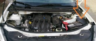
Below is the engine compartment fuse box
| Number | Description |
| 1 | Ignition switch power supply |
| 2 | Instrument panel power supply, low beam headlight switches, immobilizer |
| 3 | Power supply for instrument fuse box and relay |
| 4 | Cooling fan drive switch |
| 5 | ABS |
| 6 | ECU |
| 7 | Electric power steering |
| 8 | Cooling fan on petrol version |
Modifications after restyling in 2001 are equipped with a slightly different panel.
| Number | Purpose |
| 1 | Not applicable |
| 2 | Cooling Fan Relay Switch |
| 3/4 | Fuel pump power |
| 5 | Cooling pump drive |
| 6 | Similar only for the main fan |
| 7 | Headlight washer delay |
| 8 | Empty nest |
Main relay
Due to the design features of on-board electronic systems, it is an integral part of the ECU. The location is justified by the extreme saving of free space and simplification of the wiring design. If the relay fails, it can be replaced. A qualified specialist can quickly correct the situation.
Astra G air conditioner fuses and relays: where are they located?
The main element of the control system is located in the cabin at position F17. The duplicate is installed at number 11 in the specified block.
The compressor clutch line has increased power. Fuse links are not used here due to their low efficiency. The relay is mounted in the engine compartment under number KR 29. The switch is maintenance-free and in case of failure is replaced with a new one.
The location of the elements is relevant for versions like the 2002 GTC and other common car modifications.
Cooling fan fuses and relay: where is it located?
The design of the radiator fan power supply system is complex and has several separate switches. Voltage is supplied to the unit control unit through fuse No. 40 of the interior module. There is an insert here that supplies power to the relay switch. The part is mounted at position 50.
The fan is powered by 4/8 relays of the engine compartment module, for diesel and gasoline.
Starter fuses and relays
On cars of 2001 and 1998 they are installed near the mechanism itself. The retractor is installed as standard and in the event of a breakdown it is changed as a block. The design part of the power unit is represented by a non-separable unit and is not serviceable.
Cigarette lighter
The standard wiring is equipped with a fuse installed in 34 positions of the cabin unit. This arrangement is relevant for cars of the 1999 type.
When connecting powerful consumers to the device, users resort to a trick and run the cigarette lighter line directly from the battery. To do this, follow the procedure.
- Find a sufficient amount of cable of the required cross-section and an appropriate fuse. You will need a remote socket for it.
- The next step is to solder the socket into the break in the power line and stretch it through the engine compartment to the cigarette lighter.
This design will allow you to remove the load from the on-board network and install an additional socket in the car. Or use the highway to power high-power nodes.
Turn signals
Before and after the restyled versions of the car are equipped with a pair of 8/9 relays installed in the interior panel. Nearby is fuse 22. The insert is responsible for powering the above relays.
In some assemblies or converted cars, there are turn switches mounted separately under the dashboard. This makes it easier to access the units when servicing them.
Sound signal
Standard fuse No. 10 of the cabin unit is responsible for powering the horn and is periodically removed under the hood. This allows you to free up one slot for connecting additional equipment.
High beam
Modern Astra lamps place little load on the car's network. There is only one relay on both sides - No. 3 of the cabin unit.
There is one fuse on each side of the vehicle. Fuse links 8 and 26 are located in the interior block and are responsible for the right and left sides of the car.
On some models after 2007, the manufacturer installs a relay in the headlight unit.
Low beam
The power supply system for head optics lamps is presented similarly. Fuses numbered 6 and 24 are responsible for powering the right and left parts of the car. There is also a relay that protects the control circuits on the steering column switch - No. 2.
All elements are located in the interior mounting block. For modifications after 2011, a different location is relevant.
Where is the wiper relay located?
Structurally, the windshield wiper fuse is located in the interior panel. The relays are installed next to the drive itself under the frill. On cars after 2012, the breakers were moved under the dashboard.
Fuel pump
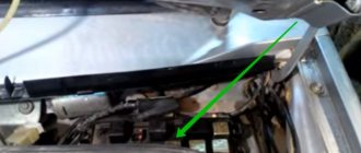
On cars manufactured after 2008 inclusive, the 3/4 inserts of the engine compartment block are responsible for powering the fuel pump. The photo shows the characteristic location of the element.
Generator regulator
The power generation apparatus relay is installed next to the installation itself and allows you to control the voltage at the output of the unit. Some users move it higher relative to its standard location. This makes it easier to access the part when servicing or replacing it.
Radio tape recorder
Standard speaker systems do not have high energy consumption. The factory fuses and lines handle system maintenance. When modifying the sound installation, installing more powerful speakers and a radio, experienced specialists recommend powering the system directly from the battery.
A separate line is stretched through the entire engine compartment. Next, a fuse of the required rating is inserted into the line and connected to the acoustics. This way you can relieve the load on the standard wiring of the machine and prevent breakdowns.
Window lifters
A fusible element responsible for the comfort system is responsible for powering the window regulators. The role of the relay is performed by the lift switch itself. If a part is damaged, it is completely replaced.
Stove
Depending on the configuration, elements can be installed in different positions. The design variability is due to the fact that different equipment requires different power and safety systems.
In most variations, the stove as such is completely absent. Its role is played by air conditioning or climate control.
Reverse
The activation sensor (frog) is mounted near the gearbox lever.
The reverse lamp is powered through its own fuse. The part is installed separately from the mounting blocks and is located under the dashboard.
EPS fuse
On modifications where power steering is used, there is no insert in the system - hydraulics do not require additional electrics. The latest modifications with power steering are equipped with a separate unit with a relay installed inside.
Parktronic
Most versions of the car do not have it. Top trim levels are equipped with separate modules. The location of the inserts should be found in the instructions for the specific vehicle.
Automatic transmission
Element No. 35 is responsible for monitoring and controlling the automatic transmission drive. Everything else is in the ECU.
Useful tips you need to know
- If you need to remove a damaged fuse, it is not recommended to use metal screwdrivers or other tools that conduct current. Otherwise, a short circuit may occur in the electrical circuit or electrical equipment;
- It is not recommended to disconnect the battery terminals while the engine is running. If you don't do this, you may pay the price with your voltage regulator and other electronic equipment;
- if it is necessary to carry out electric welding work on the car body, the connecting tips of the battery and generator must be disconnected, and the power plant ECU must also be de-energized;
- when the engine is running, you need to be very careful not to accidentally touch the elements of the ignition system and high-voltage wires;
- Another rule that must be followed: it is necessary to periodically inspect the battery terminals and connecting terminals of the wiring for contamination and oxides. If any are found, immediate cleaning should be carried out;
- Before performing any operations on electrical equipment, you should carefully study the circuit diagram to which it is connected to understand how it works.
A fuse failure cannot be determined by eye. To find out exactly where the short circuit occurred, use a lamp. To do this, the burnt-out device is removed from the seat. A lamp is connected instead. If it blinks, then there is a short in the wiring.
Using this lamp, they also check the electrical circuit for an open circuit. In this case, an additional power source is needed. The contact wires of the lamp are connected to the connecting ends of the circuit. If a glow is observed, it means that current is passing through it. Otherwise, you need to look for the break point.
In general, the process of repairing the safety block of the Opel Astra G requires only a little knowledge regarding car repairs. What is stated above is quite enough to repair the electrical equipment of your vehicle yourself.
Replacing the block
The procedure for the engine compartment and interior parts is slightly different. To remove the module located in the engine compartment, follow these steps:
- Completely disconnect the vehicle.
- Open the cover of the mounting block.
- Inside you should find 4 metal screws and unscrew them.
- Next you will need to pull the shield towards you.
- There will be a wiring contact group under the panel. The terminal must be disconnected and the panel removed.
The procedure for replacing the interior part of the module looks similar. The only difference is that due to difficult access to the block you will have to tinker a little longer. Reinstallation and reassembly is performed in the opposite order of removal.
How to replace it yourself?
To replace elements in the interior mounting block, no special tools are required. All you need is a slotted screwdriver and a set of new fuses.
Replacing fuses
Guidelines for replacing failed fuses, for example those responsible for the operation of a stove or cigarette lighter, are as follows:
- Turn off the vehicle's ignition system.
- Open the small folding box on the instrument panel, located near the knee of the driver's left leg.
- Press the plastic clips located on the sides and remove the drawer body from the frame.
- Unscrew the four slotted screws securing the frame.
- Remove the mounting block from its place by pulling the bottom part.
- Replace the faulty fuse. To do this, the damaged fuse element must be removed from the socket. The mounting block comes with small plastic pliers. They need to clamp the fuse body, pull it out of its seat and insert a new part.
- Visually check the condition of the remaining fusible links.
- Reassemble.
It is important to note that the new fuse must have the same rating as the failed one. If such a detail is missing, an element of slightly larger value can be used. Just first you need to check the working condition of the circuit; for this you should install a fuse from any other socket with the required rating. If the fuse remains intact, then a part with a higher rating should be installed instead. But at the first opportunity it should be replaced with a part with a standard rating. Since long-term use of an inappropriate fuse can lead to damage to the vehicle's electrical systems and fire. If after replacing the fuse it immediately fails, then it is necessary to find out the cause of the overload in the electrical circuit.
The process of changing fuses on more modern Opel Astra H 2008 or Opel GTC 2012 is identical to the above.
Replacing parts in the engine compartment is even simpler. To do this, you need to unfasten the plastic covers of the blocks and replace damaged fuses or relays.
Removing the relay box cover
Removing the fuse box cover