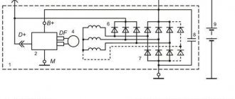
I thought about this thing last winter, when short trips around the city (home-work, home-shop, etc.) with all consumers turned on began to make themselves felt. Many people have probably heard about installing a “boost diode on the voltage regulator,” and so, after reading this article, I thought: in this situation, the voltage in the on-board network is not manually regulated, it simply becomes greater by the value by which the voltage drops when current passes through a diode. First, a little theory: when current passes through a diode, the voltage drops by an average of 0.5 volts (depending on the diode), and the standard regulator thinks that the voltage has dropped in the on-board network and makes the generator produce more voltage. Practice: we take the same circuit as for the “boost diode” and add to it a second diode and a 3-position switch, and you can use any diode, just so that it is designed for a current of at least 5A, then we assemble everything like this scheme
And voila first position 14.2 V, second position 15.4 V, third position 14.8 V
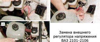
The voltage stabilizer in the on-board electrical system of a car is the most important component without any exaggeration. Not only the stability and longevity of the battery will depend on the quality of its work. At the same time, even a completely serviceable stabilization device does not always guarantee compliance with the voltage and quality of power supply of the vehicle’s electrical network. Car enthusiasts often wonder how to make the generator voltage regulator relay more reliable - contact a service station specialist, assemble or improve it yourself? There are many options.
Modern stabilizers
On modern vehicles, as a rule, self-oscillating relays are installed. They work on the principle of turning off the power to the excitation coil when the voltage reaches the upper limit of 13.5-13.8 V and connecting at the lower voltage threshold of 14.5-14.6 V.
Thus, the output voltage fluctuates constantly. Theoretically, this is not considered a disadvantage, since the voltage does not exceed acceptable limits. Still, this is not entirely safe. Surely experienced drivers know that the weak point of this type of relay is the transition moments when the rotor speed or load current changes sharply. A particularly unfavorable moment occurs with a large load current at low speeds. At these moments, voltage fluctuations often exceed the upper threshold. Due to the short duration of such surges, the battery will not fail immediately, but each time its capacity and, accordingly, resource is reduced.
This problem is solved in different ways. Sometimes car enthusiasts simply replace the self-oscillating relay with an outdated contact-vibration relay. A more optimal solution would be to replace the relay with a pulse-width stabilizer or upgrade the “native” one with the help of small additions.
Types of structures
There are 2 types of regulators: old and new. They replace each other, although they contain different fillings. The old design is equipped with a mechanical relay. VAZ cars are equipped with a voltage regulator of the PP-380 type. Devices of this series use moving contacts to switch on resistors.
This spare part has been removed from mass production. Nowadays such specimens are rare. The vibration regulator PP-380 also has a number of disadvantages. Let us point out the difficulties in operating the contact option:
- need for customization;
- step adjustment;
- periodic cleaning of the contact group;
- low reliability;
- creates radio interference;
- short service life.
SHI stabilizer
Pulse-width stabilizers are characterized by more stable operation, that is, an almost constant voltage is supplied to the vehicle network, and small deviations within the normal range are smooth. The device circuit uses the same parts as in the original, but at the same time the K561TL1 microcircuit is included. This made it possible to assemble a multivibrator and a short pulse shaper on the 1st node. The output switch control unit has also been simplified due to the use of a field-effect transistor with increased power.
Stabilizer operation cycle
When the ignition is turned on, a low logic level appears at the output of trigger DD1.1. As a result, transistor VT1 opens with the charging current of the capacitor SZ. It, in turn, begins to supply a high level to the inputs of element DD1.2, simultaneously discharging capacitor C4. When a low level appears at the output, DD1.2 opens the field-effect transistor VT3. The current from the stabilizer output flows through the excitation winding of the generator.
After the pulse stops, a high level is formed at the output of DD1.1 and transistor VT1 closes. Capacitor C4 is charged by the current passing through resistor R5 from the generator, which is controlled by transistor VT2. While the voltage on capacitor C4 drops to the lower switching limit of trigger DD1.2, it will switch. A high level will appear at its output, which will close transistor VT3. In order to protect the input circuits of the DD1 microcircuit, the voltage of capacitor C4 is limited by the diode VD4, which, when it is subsequently charged, will not lead to switching DD1.2. When a low-level pulse is again formed at the output of the generator, the process begins to repeat.
Thus, stabilization is carried out by the duration of the on state of the field-effect transistor, and the process is controlled by a measuring device, as well as a current generator. When the voltage at the generator output increases, the collector current of transistor VT2 increases. As the amperage increases, capacitor C4 begins to charge faster and the duration of the on state of transistor VT3 decreases. As a result, the current that flows through the excitation winding of the generator decreases and, of course, the output voltage of the generator decreases.
When the voltage at the output from the generator decreases, the current at the collector of transistor VT2 decreases. As a result, the charging time of capacitor C4 increases. This leads to a longer period of switching on of the transistor VT3 and the current that flows through the excitation winding of the generator increases. The generator output voltage also increases.
FakeHeader
Comments 33
Several years ago I developed a PP circuit with a temperature sensor, the same as a three-level one, only the voltage changes automatically depending on the temperature.
When I created my relay regulator, the goal was to create a reliable relay regulator that would make it easier to start the engine in winter, because... In cold weather, I had to remove the battery and heat and charge it at home, which was not convenient. When I did it, the problem with starting the engine in cold weather disappeared. Moreover, other useful qualities appeared. Like increasing battery life. The engine began to start with batteries that had not started it before (smaller capacity or old, dead ones). more stable voltage.
here's a video of how it works,
anyone interested can order from me.vk.com/id6807678
The bridge's kick came from him(((
Handsome, my friend)) I installed it for myself and also noticed such a hat. Everything flickers, today I’ll redo it +100500 for you :)
The regulator just broke. Thank you I will install it)
By the way, it is more convenient to route the wire through a large hole that looks like a circle with a rectangle. It seems to be under W. We don't have an output for this W. As far as I understand Gennady’s circuit, this is one of the generator windings (phase). This hole is on the right side of the cover (if we assume that B+ and D are on the left) and is located vertically between the holes for B+ and D.
It's clear. Why don’t you take your car for a drive?
Because I don’t like taking pictures and being photographed. I don’t even have a normal camera. You can take it, of course, but you also need to wash yourself, find a place, choose an angle, edit the photo - doing things that I don’t like. Yes, and it’s a waste of time just for this. I’d rather spend time with my daughter, or work on the typewriter, or sit at the computer ;-), or sleep =) And I have to do something along the way. And I don’t like taking photo reports (the reason is above - I don’t like taking photos).
Well done, good choice
I had one of these burnt out in August. By the way, bad man, the light was also blinking. It has been standing since the beginning of 2010. I bought the same one, but for the 10th family. There is a different current collector. But I don’t mind, I have a current collector. I put it there in the same place - on the upper mounting bolt of the right headlight (not the lower one as in the photo). Everything worked as before, although there was no blinking at all
In general, I associated the blinking with the fact that I allowed the use of a PWM (pulse width voltage amplification) circuit in the regulator. I don’t know what the actual scheme is. Why did you suspect?1
Because when using PWM, the DC voltage has a duty cycle. Those
the current flows in rectangular pulses at a frequency specified by the circuit designer (most likely there are certain recommendations for choosing this frequency)2. Now he doesn't blink. So I’m thinking, is PWM used there?
PS, gentlemen WHO INSTALLED, this is a useful device. MONITOR the voltage of the on-board network! This spring I burned Osram Night Breakers with a voltage of at least 16V ((. It’s good at least the battery is still alive. PS, the only more useful thing than this regulator is (in descending order) 1) THORN Adamchuk (thermo-optimized voltage regulator, super sophisticated) 2) voltage regulator from Chevy . He himself normally monitors the correct voltage in the on-board network. Costs a penny compared to TORN, and even cheaper than a three-level
BUT, Attention, it must be installed by an auto electrician if you don’t understand Gennady. And install it so that, if it fails, it will be easy to replace it with the same one or a native one (suddenly on the road, in a “distant village”, there will be no regulator from Chevy)
I’ll add right away that if the brushes are worn out, just change the brushes on the current collector. They are not sold separately. You can buy a cheap regulator with the same brushes, or beg a couple of burnt-out regulators from an auto electrician. Just make sure the brushes are of normal length, i.e. so that at least 2/3 of the new ones stick out. You don’t want to often climb into the genadium and solder brushes
Voltage Regulator Upgrade
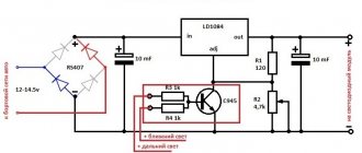
This is another option to improve the quality of the relay and its resistance to transient moments. The standard relay 50.3702-01 was taken as a basis, with only one resistor and capacitor added to the circuit.
In the diagram, the modification is indicated in red and, as you can see, does not require much effort or special experience in radio electronics. When the voltage in the on-board electrical network increases, capacitor C2 begins to charge. In this case, part of the current flows through the base of transistor VT1 and is proportional in magnitude to the rate of voltage increase. This leads to the opening of transistor VT1 and the closing of transistors VT2 and VT3. In this case, the current in the excitation coil decreases, and earlier than without an additional installed circuit. This allows you to significantly reduce voltage fluctuations in the network or eliminate them altogether. The same goes for reducing voltage. In other words, the permissible voltage limits are narrowed, and the smoothness of stabilization increases.
In this diagram, you can also introduce another rational proposal. As you know, the output voltage of the generator is optimized depending on the ambient temperature and in winter it should be higher by 0.8 V, reaching somewhere around 14.6 V. According to the standard, seasonal adjustment is performed by removing or installing jumpers S1, S2 and S3. Installing jumpers eliminates resistors R1, R2 and R3 from the circuit and the output voltage increases. When the jumpers are removed, the transistors turn on again and the voltage drops. To avoid this, the mentioned transistors can be replaced with one trimmer and the output voltage can be adjusted more easily and with greater accuracy.
A generator voltage regulator relay has been created to adjust the “voltage” supplied to the on-board network and to the battery terminals in a given range of 13.8 - 14.5 V (less often up to 14.8 V). In addition, the regulator adjusts the voltage on the self-excitation winding of the generator.
Homemade devices
Making a three-level voltage regulator with your own hands is quite difficult for an ordinary person. You should also know the basics of electronics. The main element of the device are diodes. At the same time, finding a three-stage toggle switch for them is very problematic. Additionally, radiators should be installed for cooling. Otherwise, the diodes may not withstand the maximum voltage and burn out.
The components are connected to each other using wires. They must be quite long because the cable must be threaded through the cover directly to the regulator. The last thing you need to take care of is the plastic case. In this case, the wiring in it must be well secured. As a result, switching the toggle switch should be free.
Purpose of the voltage regulator relay
Regardless of experience and driving style, the car owner cannot ensure the same engine speed at different times. That is, the crankshaft of the internal combustion engine, which transmits torque to the generator, rotates at different speeds. Accordingly, the generator produces different voltages, which is extremely dangerous for the battery and other consumers of the on-board network.
Therefore, replacing the alternator regulator relay should be done when the battery is undercharged or overcharged, the light is on, the headlights are flashing and other interruptions in the power supply to the on-board network.
Interconnection of car current sources
The vehicle contains at least two sources of electricity:
- battery - required at the moment of starting the internal combustion engine and the primary excitation of the generator winding; it does not create energy, but only consumes and accumulates at the time of recharging
- generator – powers the on-board network at any speed and recharges the battery only at high speeds
Both of these sources must be connected to the on-board network for the correct operation of the engine and other electricity consumers. If the generator breaks down, the battery will last for a maximum of 2 hours, and without the battery, the engine driving the generator rotor will not start.
There are exceptions - for example, due to the residual magnetization of the excitation winding, the standard GAZ-21 generator starts on its own, subject to constant operation of the machine. You can start a car “from a pusher” if it has a DC generator installed; with an AC device, such a trick is impossible.
Voltage regulator tasks
From a school physics course, every car enthusiast should remember the principle of operation of a generator:
- when the frame and the surrounding magnetic field move mutually, an electromotive force arises in it
- The stators serve as the electromagnet of DC generators, the EMF, accordingly, arises in the armature, the current is removed from the collector rings
- In the alternating current generator, the armature is magnetized, electricity appears in the stator windings
In a simplified way, we can imagine that the magnitude of the voltage output from the generator is influenced by the value of the magnetic force and the speed of rotation of the field. The main problem of DC generators - burning and sticking of brushes when removing large currents from the armature - has been solved by switching to alternating current generators. The excitation current supplied to the rotor to excite magnetic induction is an order of magnitude lower, making it much easier to remove electricity from a stationary stator.
However, instead of terminals “–” and “+” constantly located in space, car manufacturers received a constant change in plus and minus. Recharging the battery with alternating current is not possible in principle, so it is first rectified with a diode bridge.
From these nuances the tasks solved by the generator relay flow smoothly:
- adjusting the current in the excitation winding
- maintaining a range of 13.5 - 14.5 V in the on-board network and at the battery terminals
- cutting off the power to the excitation winding from the battery when the engine is turned off
Therefore, the voltage regulator is also called a charging relay, and the panel displays a warning light for the battery charging process. The design of alternating current generators includes a reverse current cut-off function by default.
Connection diagram for the VAZ-2101 generator
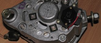
Structurally, generator 2101 consists of the following main elements:
- The rotor is a moving part that rotates from the engine crankshaft. Has an excitation winding.
- The stator is the stationary part of the generator and also has a winding.
- Front and rear covers , inside of which bearings are installed. They have eyelets for attaching to the internal combustion engine. The back cover contains a capacitor necessary to cut off the alternating current component.
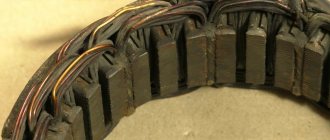
- Semiconductor bridge - called a “horseshoe” for its similarity. Three pairs of semiconductor power diodes are mounted on a horseshoe-shaped base.
- A pulley on which the VAZ-2101 generator belt is placed. The belt is V-shaped (on modern cars a multi-ribbed belt is used).
- The voltage regulator is installed in the engine compartment, away from the generator. But still it must be considered part of the structure.
- The brushes are mounted inside the generator and transmit the supply voltage to the field winding (on the rotor).
Types of regulator relays
Before you independently repair the voltage regulation device, you must take into account that there are several types of regulators:
- external – increase the maintainability of the generator
- built-in – in the rectifier plate or brush assembly
- regulating by minus - an additional wire appears
- positive regulating – economical connection scheme
- for alternating current generators - there is no function for limiting the voltage on the excitation winding, since it is built into the generator itself
- for DC generators – an additional option for cutting off the battery when the internal combustion engine is not working
- two-level - obsolete, rarely used, adjustment by springs and a small lever
- three-level – supplemented with a special comparison device board and a matching indicator
- multi-level - the circuit has 3 - 5 additional resistors and a tracking system
- transistor - not used in modern cars
- relay – improved feedback
- relay-transistor - universal circuit
- microprocessor - small dimensions, smooth adjustment of the lower/upper threshold of operation
- integral - built into brush holders, therefore they are replaced after the brushes wear out
Replacement and removal of the electric generator
The generator on a VAZ car is removed either for complete replacement in case of failure or to carry out repair work to replace faulty parts. To perform dismantling, prepare a standard set of tools; it is advisable to drive the car into the inspection hole.
- Disconnect the battery.
- Remove the protective rubber cap from terminal “30” and unscrew the nut and remove it from the wire stud.
- Disconnect the block with wires from the generator connector.
- We loosen the tightening of the generator to the adjusting bar, then lift it all the way up to the cylinder block and remove the belt from the pulleys.
- Completely unscrew the bolt securing the adjusting bar to the cylinder block, then from the bottom of the car unscrew the 2 bolts securing the lower bracket to the block and remove the generator, pulling it out of the engine compartment.
Operating principle of the regulator relay
Thanks to built-in resistors and special circuits, the relay is able to compare the amount of voltage generated by the generator. After which, too high a value leads to the relay being turned off, so as not to overcharge the battery and damage electrical appliances connected to the on-board network.
Any malfunctions lead to precisely these consequences: the battery becomes faulty or the operating budget increases sharply.
Summer/winter switch
Regardless of the season and air temperature, the operation of the generator is always stable. As soon as its pulley begins to rotate, electric current is generated by default. However, in winter the insides of the battery freeze, and it replenishes the charge much worse than in summer.
The summer/winter switches are either on the body of the voltage regulator, or the corresponding connectors are marked with this designation, which you need to find and connect the wiring to them depending on the season.
There is nothing unusual in this switch, these are just rough settings of the regulator relay, which allows you to increase the voltage at the battery terminals to 15 V.
Connection to the generator's on-board network
If, when replacing a generator, you connect a new device yourself, you need to take into account the following nuances:
- First you should check the integrity and reliability of the contact of the wire from the car body to the generator housing
- then you can connect terminal B of the regulator relay with the “+” of the generator
- Instead of “twists” that begin to heat up after 1–2 years of operation, it is better to use soldering of wires
- the factory wire must be replaced with a cable with a minimum cross-section of 6 mm2 if, instead of a standard generator, an electrical appliance rated for a current of more than 60 A is installed
- The ammeter in the generator/battery circuit shows which power source is currently higher in the on-board network
What do you need for installation?
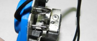
First of all, you should familiarize yourself with the equipment of the device. The standard set of the regulator includes instructions, the device itself and connecting wires with special brush holders that are needed to fix the body.
Before installing the equipment, you should prepare a spanner wrench and a Phillips-type screwdriver in advance. You will also need a knife and a voltage tester. You should use pliers to securely clamp the terminals, but regular pliers will also work.
Regulator relay diagnostics
Voltage regulator failures can be determined by indirect signs. First of all, this is incorrect battery charging:
- overcharge - the electrolyte boils away, the acid solution gets on the body parts
- undercharging - the internal combustion engine does not start, the lamps are dimly lit
However, it is preferable to diagnose with instruments - a voltmeter or tester. Any deviation from the maximum voltage value of 14.5 V (in some cars the on-board network is designed for 14.8 V) at high speeds or the minimum value of 12.8 V at low speeds becomes the reason for replacing/repairing the regulator relay.
Built-in
Most often, the voltage regulator is integrated into the generator brushes, so a level inspection of this unit is necessary:
- After removing the protective cover and loosening the screws, the brush assembly is removed out
- When the brushes are worn out (less than 5 mm of their length remains), replacement must be carried out without fail.
- Generator diagnostics with a multimeter are carried out complete with a battery or charger
- The “negative” wire from the current source is closed to the corresponding regulator plate
- The “positive” wire from the charger or battery is connected to a similar relay connector
- the tester is set to voltmeter mode 0 - 20 V, the probes are placed on the brushes
- in the range of 12.8 - 14.5 V there should be voltage between the brushes
- when the voltage increases above 14.5 V, the voltmeter needle should be at zero
In this case, instead of a voltmeter, you can use a lamp, which should light in the specified voltage range and go out when this characteristic increases above this value.
The wire that controls the tachometer (marked W only on relays for diesel engines) is tested with a multimeter in tester mode. It should have a resistance of about 10 ohms. If this value decreases, the wire is “broken” and should be replaced with a new one.
Remote
There are no differences in diagnostics for the remote relay, but it does not need to be removed from the generator housing. You can check the generator voltage regulator relay with the engine running, changing the speed from low to medium, then high. Simultaneously with the increase in speed, you need to turn on the high beams (at a minimum), the air conditioner, the monitor and other consumers (at a maximum).
Thus, if necessary, the vehicle owner can replace the standard voltage regulator relay with a more modern modification of a built-in or remote type. Diagnostics of performance is available on your own with a regular car lamp.
How to check the pH on a VAZ-2110 without removing it
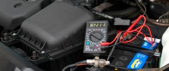
If you find at least one of the listed signs, do not be lazy to check the voltage regulator on your VAZ-2110. This procedure will not take more than 10 minutes. To do this, you will need a voltmeter or multimeter turned on in its mode, as well as an assistant. The verification procedure is as follows:
- We start the car engine and warm it up to operating temperature.
- Without turning off the engine, we connect one voltage probe of the generator, and the second to the “ground” of the device.
- We ask the assistant to turn on the low beam headlights and press the accelerator pedal, keeping the speed at 2000-2500 thousand rpm.
- We measure the voltage with the device.
For the VAZ-2110, the voltage regulator should produce 13.2-14.7 V. This is the norm. If the voltmeter readings differ from those shown, diagnostic measures should be continued.