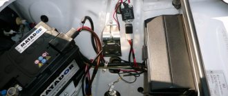
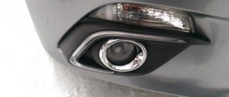
In recent years, motorists have begun to equip their cars with daytime running lights. Although the rules allow the use of standard lighting devices (fog lights, headlights, etc.) in this capacity, many prefer to make DRLs in the form of separate blocks. And some motorists are faced with the fact that the LEDs on which the lights are made fail without working for even a year. No one has found out in detail the reason for such a short service. Perhaps this is due to the quality of LEDs from unknown manufacturers, or to the fact that manufacturers greatly overestimate the declared life of semiconductor products, or maybe it’s all due to insufficient cooling.
But there is a strong opinion that LEDs fail due to unstable voltage in the car’s electrical system or due to short-term surges along the power circuit, the amplitude of which reaches several tens of volts. They are trying to escape from this disaster by installing a voltage stabilizer for the vehicle's DRL.
Stabilizer selection
In the on-board network of the car, the operating power is approximately 13 V, while most LEDs are suitable for 12 V. Therefore, they usually install a voltage stabilizer, the output of which is 12 V. Thus, normal conditions are provided for the operation of lighting equipment without emergency situations and premature failure.
At this stage, amateurs are faced with the problem of choice: many designs have been published, but not all work well. You need to choose one that is worthy of your favorite vehicle and, in addition:
- will actually work;
- will ensure the safety and security of lighting equipment.
How to choose the right one
To select an industrial device, you need to set the following parameters:
- output voltage;
- operating current;
- minimum input voltage (the maximum is usually several tens of volts; such a voltage does not exist in the car network).
How to select the output voltage is described above. The operating current must exceed the current consumption of the flashlights (or flashlight, if the stabilizer is installed on each device separately) with a margin. Few people pay attention to the last parameter, but it can have a critical impact on the operation of the entire system.
The simplest DIY voltage stabilizer
If you have no desire to buy a ready-made device, then it’s worth learning how to make a simple stabilizer yourself. It is difficult to make a pulse stabilizer in a car with your own hands. That is why it is worth taking a closer look at the selection of amateur circuits and designs of linear voltage stabilizers. The simplest and most common version of a stabilizer consists of a ready-made microcircuit and a resistor (resistance).
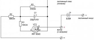
The easiest way to make a current stabilizer for LEDs with your own hands is on the LM317 chip. The assembly of parts (see figure below) is carried out on a perforated panel or a universal printed circuit board.
The device allows you to maintain a uniform glow and completely eliminate the blinking of light bulbs.
Scheme of a 5 ampere power supply with a voltage regulator from 1.5 to 12 V.
To assemble such a device yourself, you will need the following parts:
- plateau size 35*20 mm;
- chip LD1084;
- RS407 diode bridge or any small diode for reverse current;
- a power supply consisting of a transistor and two resistances. Designed to turn off the rings when the high or low beam is turned on.
In this case, the LEDs (3 pcs.) are connected in series with a current-limiting resistor that equalizes the current. This set, in turn, is connected in parallel to the next similar set of LEDs.
Manufacturing recommendations
For manufacturing, you will need electronic components for the selected circuit. You can purchase them in specialized stores or online. For a device based on an integrated linear stabilizer, a housing is not needed, but you need to take care of the radiator. You will also need a radiator when making a ruler using discrete elements. More complex devices must be assembled on boards. Those skilled in home technology will be able to design and etch the PCB themselves. For the rest, it is better to use a breadboard - cut off the required piece and mount the elements on it.
Breadboard mounting.
You also need to select or assemble the case, not forgetting about heat dissipation. Heat-shrinking the board is not the best option in this regard. You will also need a soldering iron with a set of consumables.
It is difficult to give general manufacturing instructions - it all depends on the chosen scheme and preferred technologies. But we can give some advice to those who have little experience in the manufacture of electronic devices:
- all connections must be carefully soldered (being careful not to overheat the elements and conductors in the insulation) - operating conditions will be associated with shaking and temperature changes, and poor-quality soldering will immediately make itself felt;
- the body of the structure must prevent water and dirt from getting inside - when installing the device under the hood, these substances will be sufficient;
- if the case is not used, the soldering points must be carefully isolated - for the same reasons;
- After assembly and performance testing, it would not be superfluous to coat the board on the solder side with varnish and dry it.
Only a careful approach to manufacturing can guarantee at least some long-term operation of a homemade product in harsh conditions.
Stabilizer for LEDs on the L7812 chip in cars
The current stabilizer for LEDs can be assembled on the basis of a 3-pin DC voltage regulator (L7812 series). The mounted device is perfect for powering both LED strips and individual light bulbs in a car.
Required components to assemble such a circuit:
- chip L7812;
- capacitor 330 uF 16 V;
- capacitor 100 uF 16 V;
- 1 ampere rectifier diode (1N4001, for example, or a similar Schottky diode);
- wires;
- heat shrink 3 mm.
There can actually be many options.
Feasibility of using LT 1083/84/85
The 12 volt voltage stabilizer circuit may have different ICs. Depending on the series of the microcircuit, the conditions for its operation vary. Microassemblies of the LT 1083/84/85 series can be used to manufacture a stabilizer for this voltage.
For your information. The output current of the LT 1083 can reach 7 A; on the LT 1084 and LT 1085 the permissible load currents are 5 A and 3 A, respectively.
Designers for radio amateurs, supplied from China, offer to independently assemble a simple power supply circuit on a similar stabilizer platform.
The stabilizer included in this circuit produces an output current of up to 7.4 A. Resistor R2, which allows you to change the output voltage, can be replaced with a constant, selecting its value so that U at the output is equal to 12 V. Diodes are selected for a voltage of at least 50 V and current not less than 12 A.
Attention! The voltage on this chip requires a voltage difference between the input and output of at least 1.5 V. If this condition is met, the IC will output a stable voltage. At the same time, it has thermal protection and protection against exceeding the output current value.
Connection diagram based on LM2940CT-12.0
The stabilizer body can be made of almost any material except wood. When using more than ten LEDs, it is recommended to attach an aluminum radiator to the stabilizer.
Maybe someone has tried it and will say that you can easily do without unnecessary troubles by directly connecting the LEDs. But in this case, the latter will be in unfavorable conditions most of the time, and therefore will not last long or will burn out altogether. But tuning expensive cars results in a fairly large sum.
As for the described schemes, their main advantage is simplicity. Manufacturing does not require any special skills or abilities. However, if the circuit is too complex, then assembling it with your own hands becomes unreasonable.
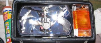
Testing homemade LED headlights
After about 2 hours of testing, the system reached a temperature of about 35 degrees, that is, despite the use of resistors instead of chip inverters, much less than an equivalent incandescent lamp.
The uniformity of backlight shades is not ideal. The lower part of the headlights is good - the diodes shine perfectly with rows of lenses and illuminate evenly. Higher up - due to the tilt of the glass LEDs, the light begins to scatter a little, and the brightness depends slightly on the viewing angle.
It would have been possible to customize the LED strips in stages, but the priority was to provide a reasonable cost-to-effort ratio that would completely satisfy the car owner.
- After a month of testing, when the car traveled about 2 thousand kilometers, not a single LED burned out. Let's see how it goes next.
- After a year of driving, when the car traveled about 10,000 km, one diode was burned out and one strip went out. Probably turned out to be defective.
The time investment for these car tail lights is 3 days to 2-3 hours a day, and the cost of materials for both lamps is 3000 rubles - this is very good.
Connection via a 4-pin relay from a generator or oil sensor
The following two methods have a common basis and imply the operation of daytime running lights only after the engine is started. The circuit for switching on DRL from the generator is based on switching a four-contact relay and a reed switch. The DRL relay contacts are connected as follows:
- 85 – to the positive wire to the dimensions;
- 86 – to any reed switch output;
- 87 and the second terminal of the reed switch - to the “+” of the battery.
After checking the reliability of all contacts, proceed to setup. To do this, start the engine and, by moving the reed switch near the generator, achieve its activation and a stable glow of the DRL. Then the reed switch is hidden in a thermal tube and fixed in the found place using nylon ties.
At the moment of starting the engine, and then the generator, the contacts of the reed switch and relay close, supplying power to the LED running lights. In this case, the side lamps remain turned off, since the current through the relay coil is small to light them.
In the absence of a reed switch, you can power the DRL from the oil pressure sensor. In this case, pin 86 is connected to the oil pressure lamp. The rest of the circuitry is duplicated. Both schemes have a common drawback. They cannot be used if LEDs are installed in the dimensions.
My experience
My friend has a VAZ PRIORA, and he is a fan of putting LED lamps in the dimensions, headlights, etc. They really didn’t walk for a long time without such stabilizing elements (a couple of months, that’s all). Now one set of cheap options has been running for three years, and all thanks to stabilization!
There are also disadvantages: such elements are placed in the break of the wire that goes to the source; “IN” and “OUT” are even indicated there where the wire should be connected and where to output it. The cost for 5 pieces is approximately 160 rubles, that is, each one is about 30. A friend set it to 11.8V, connected the wires to the boards and filled them with a glue gun, now they are not afraid of moisture.
Personally, I myself bought such boards and experimented with them, I have a power supply that produces from 15 to 24V. From it I powered two wires and connected them to the module, and from there to the LED, I set it to about 11.9. And you know, no matter how I switched the voltage in the power supply, behind the board it remained stable at 11.9V without any jumps (the whole experiment will be on video).
So the conclusion is that you can buy stabilizers (about 30 rubles apiece), the light bulbs themselves (about 50 rubles apiece) and in TOTAL you get an option for 80 - 100 rubles that will work for a very long time (3 years for sure).
Now we are watching the video version
Here is the material, I think it was useful to you, subscribe to the site and the channel will have many more interesting videos. Sincerely yours, AUTOBLOGGER.
Similar news
- Why does the alternator belt whistle? When cold or under load. ...
- How to install xenon. Is it possible to do this in the headlights of a regular car...
- How to check a fuse in a car. We use a multimeter (test...
Add a comment Cancel reply
Operating mode
According to technical regulations for cars, DRL should automatically turn on when the engine starts. When you turn on the low beams, they should turn off automatically so as not to dazzle at night.
There are also combined models with installed turn signals on sale. The turn signal duplication section is connected separately in parallel to the standard turn signals. Having a stable diet is also a must.
DRL with turn signal
For models with additional control, there is a follow-up backlight function that operates for 10 minutes after the engine is turned off. It illuminates your path to your home or dugout, depending on where you live. Osram DRL has a mode in which they do not turn off, but dim by 50%. I just don’t know how legal it is and whether it will cause blindness.
Other less popular methods
Many people are interested in how to connect DRLs without a relay on their own, but it depends on the electrical system of your car; look for a solution in online clubs dedicated to your car. The most important thing is that power is supplied to this place after the engine starts.
The basic diagram for connecting the DRLs is through a 4 or 5 contact relay, which turns off when the low one is turned on. Those who are not too lazy to rummage through the car’s wiring can connect it from the oil pressure sensor or generator. On any vehicle, when the engine starts, the oil pressure light on the dashboard lights up, the signal from this wire is used to supply power. The second way to connect running lights yourself is to connect to a generator. They will turn on automatically when voltage appears on the generator.
Choosing a belt for the machine
I’ll try not to pour water, but will briefly look at what to look for when choosing an LED strip
LED Matrix Type
LED interior lighting. To illuminate the car interior, including the trunk, choose SMD 3528 60pcs/m (the size of one LED crystal is 3.5x2.8mm). Why she?
Firstly, we get an average power of 4.4-4.8 W per linear meter with a luminous flux of about 250-300 Lm. With such power, LEDs do not require heat dissipation and the LED strip can be easily mounted on plastic elements. And the luminous flux is sufficient to fully illuminate any interior elements.
Secondly, this is the most common tape on sale, we buy it in the first store we come across.
Options like SMD 5050, 5630, 5730 are not suitable due to their high power. Unpleasantly high brightness and the need to mount a heat sink make them not the best choice for LED car interior lighting.
Exterior car lighting. Here we turn on the head. If there is LED lighting under the bottom of the car, you can choose more powerful LEDs - SMD 5050 30/60 pcs/m. The aluminum profile will be our heat sink (more about installation later). For LED illumination of license plates or (God forbid) headlights, this is a bad choice. Such LED lighting will be a bait for traffic police inspectors (read about installation rules and fines at the end of the article).
Regular LEDs or RGB - there is no difference. RGB is a little more expensive, it is more difficult to connect and requires an additional control controller (read more about connecting an RGB strip). But it allows you to change the backlight color.
Protection class
There are mainly three protection classes on sale - IP20, IP65, IP68.
- IP20 – open tape without protective coatings, suitable for use indoors in dry rooms. Afraid of moisture, dust, and any mechanical influences.
- IP65 – with a protective silicone layer that can protect against condensation.
- IP68 - sealed, waterproof LEDs that can be placed on the bottom of the car.
LED class IP68 For LED illumination of the glove compartment or the bottom of the dashboard, IP20 is also suitable if no one pulls it or pours water on it. For illumination of other elements, IP class 65-68 is desirable.
Add a link to a discussion of the article on the forum
RadioKot >Schemes >Power >Converters and UPS >
| Article tags: | Add a tag |
Dual-mode current stabilizer stop/marker for LED car lamps
Author: KomSoft, Published 04/13/2017 Created using KotoEd.
Quite often they bring car LED lamps, which are beautifully made, but happily burn out. Their giblets consist of the LEDs themselves, a resistor (like the “gauge” lights up) and a diode (like the “stop” lights up). These are cheap ones - but I haven’t gotten my hands on expensive ones, perhaps they are made of better quality.
Therefore, I would like to improve them as little as possible. There are a lot of schemes like these floating around on the Internet:
These circuits do not have current stabilization. The first stabilizes the voltage, the second at “stop” also stabilizes the voltage, and at “gain” adds PWM to it. Not bad, but LD1084 is a bit expensive, and the second one contains a lot of parts.
There is a simple linear current stabilizer
So we’ll start from that and try to stuff it into the base of a P21/5W lamp, not forgetting about heating the stabilizer elements. Let's draw a diagram:
Diodes VD1, VD2 decouple the stop and parking signals, transistors Q1 and Q3 form a current stabilizer, transistor Q2 switches modes.
The minimum on-board voltage is 12V. We assemble the LEDs into a matrix (cluster) with a voltage as close to 10V as possible, so that less is spent on heating the circuit. We leave 2 volts for the VD1/VD2+Q1+R5/R4 chain.
When voltage is applied to B(Break/Brake), transistor Q2 is open, the channel voltage is close to 0 and the stabilization current is determined by resistor R5.
When voltage is applied to T(Tail/dimension), Q2 is closed and the stabilization current is determined by the sum of resistors R4+R5.
The heaviest mode in terms of heating will be “stop” when the maximum current stabilizes. Especially if it’s in the summer in the heat in a traffic jam. The light shines dimly, and the turn signal blinks - so it will be easier in these modes.
About choosing parts:
Schottky diodes must withstand the maximum LED current (up to 1A) and a voltage of 20-40V.
Resistor R5 is selected according to the formula R5 = 0.7 / IB, because when you press the brake, Q2 opens and almost all the voltage (0.7V) drops to R5, and a little more to Q2 (depending on the channel resistance, see below). Its power at currents up to 1A is enough to be 1W or 0.5W at currents up to 0.6A. IB is the desired current in stop mode.
Resistor R4 is selected according to the formula R4 = 0.7 / IB - R5, according to the desired brightness of the all-diodes for the dimensions. Most likely to choose experimentally. Its power is sufficiently 0.125W.
Transistor Q2 operates in switching mode, therefore it dissipates low power of 0.05 W, the channel resistance in the open state should be as low as possible. IRML0030, IRML2030, IRML6344 should be suitable.
Transistor Q1 must dissipate a relatively large power of 1-2W; the channel resistance in the open state is not so important, since everything works due to it. IRFL014, IRFL110, IRFL410, IRFL4105, IRFL4310, IRFR320, IRLL2703, IRLL2705, IRLR024, IRFU310 should be suitable. Case SOT-223, power 1W, Rds = 0.16.
Transistors were selected according to these criteria and the minimum price.
In order to minimize price and space, you can try the IRF7301, IRF7303 and IRF7341 assemblies - 2W power, Rds = 0.05, SO-8 package.
The circuit was simulated in Proteus - LED-IStab.DSN. Below is a table of currents, voltages and power at an on-board voltage of 16V, a drop across the LEDs of 9V and different currents through the LEDs. The results are approximate, but give an idea of the order of magnitude for selecting elements.
| Iled = 0.07A | Iled = 0.18A | |||
| U, V | P,W | U, V | P,W | |
| Q1 | 5 | 0.35 | 5.1 | 0.9 |
| R4 | 0.2 | 0.014 | 0.5 | 0.09 |
| Q2,R5 | 0.5 | 0.04 | 0.2 | 0.04 |
It was all a theory that had been pretending for a long time, and practice, as always, made its own adjustments.
Practical implementation.
Hundreds of LEDs were ordered from well-known trading platforms (up to 40 pieces are needed per lamp, depending on color/current/voltage). Ordered white 5630, yellow 5050 and red 5050.
Their stated parameters are:
| Red | Yellow | WarmWhite | Red/Yellow | Green/Blue | |
| Model Number | SX-5050-RED | SX-5050-YELLOW | 5630/5730 | 5630/5730 | 5630/5730 |
| Max. Forward Voltage | 2.0-2.6V | 2.0-2.6V | 3.0-3.2V 3.2-3.5V | 2.0-2.4V | 3.2-3.5V |
| Max. Forward Current | 20-60mA | 60mA | 150mA | 150mA | 150mA |
| CAT | 10-20LM | 800-1200mcd | 50-55LM 60-65LM | 22LM/15-18LM | 32-35LM / 12-15LM |
Or according to another sign:
Unfortunately, yellow and red LEDs were disappointing - they are much less bright than white ones. But they have a lower operating voltage, so you can supply more of them.
When laying out the board, I had to make a compromise and simplify the circuit a little, namely, remove the stabilization for the dimensions (on a single-sided board it did not fit into the dimensions of the base, and I don’t want to make a double-sided board, since the task is to make it as simple as possible). This compromise leads to the fact that when the voltage (motor speed) changes, the brightness will change slightly, but the maximum current will not be exceeded, which meets the requirements. In this case, 2 elements are saved (two resistors and a transistor are removed, and one resistor is added). If you make only single-pin “light bulbs”, then you can assemble them on the same board without soldering D1, R6, R7, and replace D2 with a jumper. You can also save money by distributing the board only for the necessary parts. Resistors R6-R7, R9-R10 are placed in pairs so as not to exceed the power dissipation. The calculation gives the total resistance (i.e., when installing two resistors in parallel, it must be multiplied by 2).
Here is the calculation (screenshot) for 8 columns of 5 red 5050 LEDs with a stated flux of 10-15lm at a current of 60mA (20 per LED) and a voltage drop of 2.1V. The 1R58 resistor (there were just a lot of them - soldered from hard drive boards) gives a calculated current of 380mA for everything, i.e. 47.5mA per column or 16mA per diode. The stabilization current is chosen so that if one line burns out (or loses contact) it does not exceed the maximum current of the LEDs. Those. when assembling 8 lines, selects an operating current slightly less than 7/8 of the maximum. The power on the stabilizer transistor is 0.8 W, the overheating of the stabilizer transistor is 50°.
The current begins to stabilize from 13.4V. In reality, when turned on (warming up), it decreases from 400mA to 360mA.
Resistors R6, R7 of 62 Ohms are installed in the dimensions With dimensions, the current changes from 80mA (at 13V) to 120mA at 15V, and the brightness changes accordingly, but not much.
Visually, when installed in the headlight, the brightness of the headlight is approximately the same, and the brightness in the stop/turn mode is slightly less than that of the yellow turn signal 21W.
After 20 min. continuous operation at 15V it gets hot (LEDs and transistor), at a voltage of 14.5V the LEDs are hotter than the transistor (you can hold your finger on the transistor).
The second option is assembled with 5630 LEDs (150mA/55lm). According to the datasheet, the relationship is linear, i.e. at a current of 75mA it will be about 27lm. Voltage drop: 20mA - 3.08V, 50mA - 3.4V, 100mA - 3.9V. With 3*8=24 LEDs it will be approx. 650 lm is very good.
The theory has almost been put into practice, we are starting to collective farm!
The stabilizer board looks like this, dimensions 1300 * 500 mils, i.e. approximately 32.5 * 12.5 mm
LED scarves are provided at the end of the article in .lay format. When assembling, the LEDs need to be installed with the positive side to the base, then the driver board can be soldered with the pin up into the LED board. This is what soldered boards look like - 8 lines, an end and a stabilizer board. I soldered 10 ohm resistors in series with the LEDs to slightly balance the currents. For 5050 LEDs, the resistors are soldered on the end board.
The rectangular (rather than trepezoidal) shape of the rulers (petals) will ensure ventilation of the stabilizer elements. For assembly, a high-tech auxiliary device is used, made of cardboard, the diameter of the thin part is 14mm. This is the diameter of the upper (expanded) part of the base, with the boards placed on the horizontal part of the base. The thick part of the paper sleeve serves as a stop; it is 2-3 mm larger. An additional element is an elastic band.
Now we secure the boards around the circumference with an elastic band and, one by one, moving them away, insert the end part. It doesn't work the first time, but it's quite simple. Then (without removing the elastic) we align it.
We solder it with L-shaped brackets (creating an electrical junction) and solder the anodes (resistors) around the circumference, creating a common positive contact and securing the other end of the structure. We don’t touch the lower platforms! They are used for soldering to the base, and this is a minus! It turns out quite tough. Calmly remove it from the mandrel and level the lower end with sandpaper.
Having checked it in advance, we solder the stabilizer board and put heat shrink on its lower end so that it does not short-circuit on the base.
It should be noted that the side view of the base is drawn incorrectly everywhere! The correct type of base corresponds to the picture, where the lamp has a bulb and the protrusion is directed towards us (second from the left). In the next picture (bottom) it’s already wrong, but in the top one it’s correct! Those. if you look at the lamp so that the left side protrusion is higher and the right side is lower, then there is no right and left contact at the bottom, but there is a near and far contact. Near (upper) - STOP, far (lower) - SIZE.
We solder the “anode” of the lamp (wire along the circumference) to the stabilizer, check again, solder the stabilizer into the upper end of the lamp (LED cathodes). Now, using 4 U-shaped brackets, we solder the lower pads (one at a time) to the base, without connecting the base to the “anode”!
The manufacturing result is shown in the table.
| Option 1 | Option 2 | |||
| LED type | 5050 | 5630 | ||
| Number of LEDs | 40 (8*5) | 24 (8*3) | ||
| Diameter (top), mm | 29 | 29 | ||
| Overall length, mm | 56 | 50 | ||
| Mode | "dimension" | "stop" | "dimension" | "stop" |
| Current at 12V, mA | 40 | 200 | 40 | 280 |
| Current at 13V, mA | 62 | 310 | 56 | 400 |
| Current at 14V, mA | 85 | 380 | 70 | 540 |
| Current at 15V, mA | 108 | 350-380 | 85 | 540-600 |
| Current stabilization start voltage, V | 13,5 | 14-14,4 | ||
| Pconsumption (max), W (at 15V) | 1,62 | 5,7 | 1,28 | 9 |
*When the structure (LEDs and stabilizer) heats up, the stabilization current decreases.
The dimensions of the lamps turned out to be slightly larger than the standard ones (by 4 mm in diameter), and the 5050 LEDs were 6 mm longer, but they fit without any problems.
When installed in a car, you can see that the WarmWhite 5630 side-turn signal shines brighter in side-signal mode, but normally in turn-signal mode. That is, you need to increase the resistor R6-R7 so that the difference when switching is more noticeable (in the photo above - clearance mode, below - turn / emergency lights).
I didn’t take pictures of the rear dimensions/stops, but I can say that subjectively the lamp assembled on red LEDs is not bright enough. But red LEDs have a nicer glow, which in my opinion is better than using white ones and relying on a light filter.
PS LED lamps went from spring to autumn (in the sense of hot summer) without incident. Don’t scold the car, it served its purpose honestly, but unfortunately in the fall it flew away to a better world..., leaving the light bulbs as a souvenir.
Actually, it is not necessary to “collectively farm” the design of LEDs; insert such a stabilizer into ready-made LED lamps in order to stabilize the current and extend their life, if, of course, the design (assembly) of the LEDs itself is made with high quality.
No nail, no rod!
Files:
Boards (.lay) and simulation in Proteus Calculation (Excel format)
All questions in the Forum.
| What do you think of this article? | Did this device work for you? | |
| 31 | 9 | 8 |
DRL control unit
The most reliable and simplest option is to connect DRLs without a relay, but using a special running lights control unit. It ensures that the DRL turns on after starting the engine, guarantees safe operation, protects against overloads and can be installed on cars with any type of lamps, including LEDs.
Unfortunately, among the variety of industrially manufactured DRL units, the vast majority do not comply with GOST and have mediocre build quality.
This applies, first of all, to products from AliExpress, which do not meet the requirements in almost all respects.
Among all the diversity, only 2 options can be noted: the Russian DayLight+ DRL control unit and German products from Philips and Osram. The DayLight+ control unit was developed by Russian radio engineer Fedor Isachenkov, taking into account all the features of the vehicle’s on-board network and has a number of positive aspects:
- there is built-in voltage stabilization;
- full compliance with GOST;
- the maximum long-term load power is 36 Watts (significantly less is required for DRLs);
- simplest connection diagram.
In addition to the points described above, the DayLight+ unit is universal and is suitable for all cars with an on-board 12-volt network, and also has good build quality and a high degree of protection from moisture and dust. German products from Philips and Osram also have all the above-described advantages of the DayLight+ unit, however, German control units are supplied only together with daytime running lights and are more expensive.