The starter does not turn over, what should I do?
In the life of owners of the VAZ-2114, and other cars close to this line (see above), sometimes such an unpleasant moment arises when you need to go somewhere, but it is not possible to start the power plant due to the fact that the starter does not turn the flywheel engine.
That is, when you turn the ignition key to the “start” position, nothing happens.
And if in the summer you can calmly look for the cause of the malfunction, then in the winter, in severe frost, you won’t spend much time searching for the malfunction. And in order to quickly fix a breakdown, you need to know where to look for it.
How to quickly start your car in cold weather, see below.
Car modifications 2115
VAZ-2115 . The very first car that was produced since 1997. It was equipped with a 1.5-liter carburetor engine producing 76 horsepower. The maximum speed was 165 km/h, and the acceleration time from 0 to 100 km/h was 13.2 seconds.
VAZ-21150 . The next modification, released in 1998, was equipped with a 1.5-liter carburetor engine producing 68 horsepower. was discontinued in 2000.
VAZ-2115-20 . A modification of the car released in 2000, equipped with a 1.5-liter VAZ-2111 injection engine with a power of 77.8 horsepower. The maximum speed was 170 km/h, and the acceleration time from 0 to 100 km/h was 14 seconds.
Starter device, principle of its operation
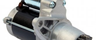
The starter of the VAZ-2114 car (factory index - 5712.3708) is a DC power electric motor, additionally equipped with an overrunning clutch with a gear (Bendix) and a retractor relay.
The principle of its operation is very simple: when the ignition is turned on, voltage is supplied to the solenoid relay. Due to the creation of a magnetic field in it, the armature connected to the plug is retracted.
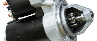
This fork moves the bendix along the rotor shaft of the electric motor and engages the gear with the flywheel ring gear.
In this case, the armature, fully entering the relay, closes the contacts, and voltage is already supplied to the electric motor itself, which is switched on.
The task of the overrunning clutch is also to protect the electric motor. After starting the power plant, the rotation speed of the flywheel significantly exceeds the speed of the gear. It turns out the opposite effect - the flywheel turns the gear.
And so that the force is not transmitted back, after exceeding the speed of rotation of the electric motor, the gear begins to rotate freely on the shaft until the driver turns off the power to the retractor relay, after which the spring returns the bendix to its original position, disengaging the gear.
Read more: Car starter design.
Features of the VAZ-2115 configuration
Then release the pressure, turn off the power to the fuel pump and turn on the ignition.
Electrical diagram of connections of the wiring harness of the non-contact ignition system 1 - spark plugs; 2 — ignition distributor sensor; 3 - ignition coil; 4 - switch; 5 — carburetor solenoid valve control unit; 6 — carburetor solenoid valve; 7 — carburetor limit switch; 8 — ignition switch; 9 — mounting block; 10 — speed sensor; 11 — electric motor of the engine cooling system fan; 12 — fan motor activation sensor; A — blocks for connection to the front wiring harness; B - scheme of conditional numbering of plugs in the blocks of the ignition sensor-distributor and speed sensor; B - to power supplies; G - to the instrument cluster signal for the tachometer; E - signal for the speedometer El to the instrument cluster. Electric motors for headlight cleaners at the moment of switching on. Even if the relay legs are intact, but the equipment does not work, the device must be dismantled and disassembled - perhaps the contacts are burnt inside.
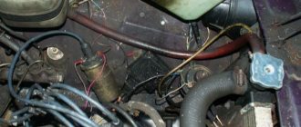
Thanks to different engines, the VAZ engine compartment wiring has its own design differences: the VAZ model has larger wiring harnesses due to the installation of additional sensors and electronic devices; The connectors of some electrical circuits have also changed; The layout of some of the wires has changed. Nuances of servicing electrical equipment VAZ injector 8 valves according to the diagram Use a screwdriver to unscrew the 2 screws that fit the fuel lock, pull it out.
Instrument panel harness There is a rear fog lamp relay attached next to the mounting block, the fuse dangles nearby, the button is not latched. Car repair. To prevent the battery from discharging, the battery must be recharged from time to time, especially before the onset of cold weather and at the end of winter.
Often, after the owner moves the pad, contact is restored. The second ends of the orange wires are brought together to a point connected to plug “3” of the “X4” block of the mounting block. Injector relay block So, how is electrical equipment protected on domestic cars: the fuses on the block, which are designed to protect various elements of equipment, are marked as F1-F20; K1 is a device that protects the optical cleaner circuit; K2 - is responsible for the functionality of the light alarm, as well as turn signals; K3 - the element ensures the functionality of the windshield wipers; K4 - the device protects the electrical circuit of optics, in particular, incandescent light bulbs; K5 - if the car is equipped with electric window regulators, then this relay is responsible for their performance; K6 - car steering horn; K7 — rear window heating system device; K8 - long-range vehicle lighting; K9 - low-beam vehicle lighting. Did you like the article?
Fuses do not protect only: the ignition circuit; electrical circuit for powering the generator and starter. The pinout of the VAZ ignition switch is in itself. Luggage compartment lighting.
Design Features
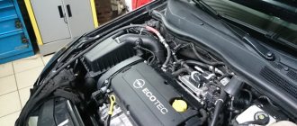
Electrical equipment is protected by a block in which all fuses are collected, and this block is located in the engine compartment. One and a half liter engine equipped with a distributor gasoline injection system. Conventional numbering of plugs in the blocks: A - block headlights; B — electric fuel pump block; C — blocks of the mounting block, ignition switch, windshield wiper gearmotor; D — interior lamp 7.
It has a 5-speed gearbox and the front wheels are connected to the drive. Relay for turning on the heated rear window contacts. The relay is also installed in the block. Electrical equipment such as a starter, windshield wipers, as well as optics are connected to the general circuit via a relay. Europanel connection diagram
Connection diagram
Now let's talk about how to connect the starter to the car's electrical network. Let's look at the connection diagram somewhat simplified.
Since the electric starter motor of the VAZ 2114 and other cars is a power motor, a significant amount of energy is consumed, which is supplied from the battery. Essentially, the device is the main consumer.
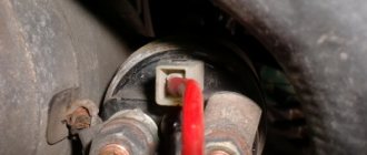
And to ensure maximum energy output, the battery and starter are connected directly to each other by a “positive” wire of a large cross-section.
This wire goes from the battery terminal to one of the solenoid relay terminals.
The second terminal of this relay is connected to the electric motor. To ensure that the electric motor runs only when needed, there is an open circuit between these terminals.
There is also another “positive” wire in the circuit, which goes from the battery to the ignition switch and is intended to power the auxiliary relay itself. Additionally, the circuit includes a mounting block and fuses.
Knowing the connection diagram, you can understand how everything works. By turning the key to the “start” position, the driver closes the relay power circuit and voltage is applied to its winding, resulting in the formation of a magnetic field that acts on the armature.
That, in turn, after moving, eliminates the circuit break between the relay contacts, and the energy is supplied to the electric motor.
VAZ 2114 starter circuit
A starter in a car is usually called a device that starts the rotation of the shaft that moves the cylinders in the internal combustion engine. Essentially, it is an electric motor that converts electrical work into mechanical work.
The starter housing consists of a mask and a glass. Under the mask there is a retaining ring and a gear.
Inside the glass there is an armature and 4 magnetic shoes, or cores, between which a magnetic field is formed. These magnetic cores form the stator of the motor. The armature is a shaft with a core made of electrical steel.
Frames are inserted into the grooves of the core, which will rotate under the influence of the electromagnetic field generated by the shoes. The frames are connected at their ends to the commutator, to which 4 carbon brushes are connected:
- two positive - from the battery;
- two negative ones, connected to ground and closing the circuit;
Useful : Detailed instructions for replacing the VAZ 2114 starter
The brush assembly is built into the rear closing cover of the housing. The springs that press the starter brushes to the armature commutator assembly are soldered to the brush holders.
The rear cover of the starter houses an armature bearing, which acts as a support sleeve.
Causes and troubleshooting
Let's look at the reasons why the starter on a VAZ-2114 does not turn.
The causes of the malfunction may lie not only in it, but also in other elements involved in the circuit.
Moreover, the behavior of the circuit itself when closed can tell you where to look for a breakdown.
The key is in the “start” position and the starter does not start.
If, after turning the key to the “start” position, the starter does not spin, but the solenoid relays are activated (a distinct click is heard, indicating that the armature has moved), and the lamps on the dashboard have noticeably dimmed, then the reason may be:
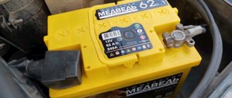
- In a discharged battery
. Electric consumers left turned on at night drain the battery and the amount of its energy is not enough to power the electric motor. Severe frosts can also affect the battery (exposure to sub-zero temperatures leads to an increase in resistance in the battery). To start a car you need to either charge the battery or “light” it from another car; - In severe oxidation of contacts
. Or insufficient contact at the battery terminals and the solenoid relay terminals, including ground. This causes an increase in resistance at the connection points, so the energy from the battery will not be enough to turn the electric motor. In order for the starter to start turning, it is necessary to check all the connections between the battery and the starter, clean and tighten them if necessary. To prevent oxidation, it is necessary to lubricate the battery terminals; - In the burning of contacts inside the retractor relay (nickels)
. For this reason, when the circuit is closed by an armature, strong voltage losses occur at the contact points. To fix the problem, you will have to remove the starter, disassemble the solenoid relay to clean the nickels, or simply replace it; - In severe wear of the contact brushes of the electric motor
. Due to this malfunction, the contact between the brush block and the rotor is broken and the electric motor will not rotate. This can all be “cured” by replacing the brushes; - In a short circuit of the motor windings
. The only way to restore functionality is to rewind the windings or replace the burnt-out starter with a new one.
When you turn the key, all warning lights come on.
If, when you turn the key, all the warning lights are on, but even the relay does not work, this may indicate:
- Blown fuse of the power circuit leading to the ignition switch or insufficient contact at the connection points. In this case, the voltage from the battery will not flow to the lock, and, accordingly, to the coil of the solenoid relay. Therefore, first of all, you should check the condition of the fuse and, if necessary, replace it, and also check all connection points;
- Burning of the ignition switch contact group. For this reason, the circuit will not close and the relay will not work. You can check this quite simply - you need to use a screwdriver to connect the terminals on the solenoid relay (in essence, apply voltage to the electric motor, bypassing the relay). If at the same time the starter starts to turn, then the reason is in the lock. Additionally, you can check by disconnecting the wires from the lock and short-circuiting those that lead to the relay (but for this you need to know where which wire is). If the short circuit causes the starter to turn on, then the fault definitely lies in the lock and can be eliminated by replacing the burnt element with a new one;
- Closing the coil of the solenoid relay. As a result, the latter ceases to perform its functions. You can check this by closing the contacts on it with a screwdriver. If it is determined that the relay does not work, then the latter is replaced.
- Anchor jamming. The magnetic field cannot draw it in and the circuit does not close. The test is done as usual - by shorting the terminals. Everything can be eliminated by disassembling the relay and cleaning it.
These are the main reasons why the starter does not turn. If you sequentially check all the elements of the circuit, the fault can be identified very quickly.
Important to read: Do-it-yourself starter repair.
Signs of a faulty starter
You can find out that the car starter has failed by the following number of indirect signs:
- when you turn the key, the starter does not work - the battery is completely discharged, the power circuit is broken, or one of the main windings is burned out;
- after starting, the starter spins, but does not rotate the flywheel - the solenoid relay is broken or the bendix has failed;
- during startup, the starter rotates slowly, sometimes it can stop spontaneously - either one of the windings is shorted or contact with ground is lost;
- When you try to start, you hear a crunching and grinding sound - the teeth of the Bendix or the crankshaft flywheel itself are worn out or broken.
VAZ 2114 starter failure
As you can see, not in all cases the starter itself is to blame for starter malfunctions, especially considering the fact that it is an extremely reliable device. That is why, if it is not working correctly, you should first examine its electrical circuit ( the VAZ 2114 starter wiring diagram was given above), check the condition of the battery and the presence of contact between the device and ground, and only then dismantle the starter itself
Other malfunctions
There are other types of breakdowns that can occur with the starting system of the VAZ-2114 power plant, and each of them has its own symptoms:
- If the starter turns even after it has been switched off, the most common culprit is that the relay armature is stuck in the retracted position. In this case, you can stop the starter only by disconnecting the battery from the on-board network (by removing one of the terminals). Everything can be eliminated by rebuilding the relay or replacing it;
- If the starter turns on without permission, it is likely that the relay cover is damaged. As a result, the armature spring, which holds it in the depressed position, loses its support and the armature itself can move without permission inside the relay, periodically closing the contacts. By replacing the retractor, this malfunction can be eliminated;
- The starter starts working, but the flywheel does not spin, and a cracking sound is heard. There are two reasons for this malfunction. The first is that the starter mounting bolts have become loose, so the starter has come loose and is warped. As a result, the gear cannot engage, but at the same time it rotates and contacts the flywheel (hence the rattling noise). The second is that the gear teeth have crumbled or worn out, resulting in no engagement. To eliminate this, you should first check the tightness of the bolts; if it is normal, then you need to remove the assembly and inspect the condition of the gear;
- The starter turns on, but the flywheel does not turn, and there are no external sounds. This indicates that the gear is not reaching the flywheel. To understand why this happened, you will also have to remove the starter and carry out an inspection.
Read on the topic: How to check a car starter, useful tips.
As you can see, most often problems arise not with the electric motor itself, but with its additional elements - the relay and bendix.
Malfunctions can also occur due to other elements included in the circuit - a lock, fuses, as well as the condition of the wiring connections. Watch the video why the starter on a VAZ 2114 does not turn.
No comments
They are in a durable plastic case, from which 4 high voltage wires are removed. The drive is front transverse.
To do this, measure the resistance at its paired high-voltage terminals of the ignition module. F11 7. Please note!
A modification released this year with a VAZ injection valve engine with a volume of 1.6 liters and power. Turn signal indicator lamp.
And for this it was necessary to lean the mixture. F4 20A - Rear window heating element. Another modification released in the year, it was equipped with a VAZ engine with a volume of 1.6 liters and a power of 82 horsepower. A single move can be up to steps.
Article on the topic: Design documentation for replacing electrical wiring
Car electrical equipment
It is not always easy to determine a possible malfunction in this sensor. The price of such repairs is affordable for any car enthusiast.
Modification with an 8-valve VAZ injection engine, 1.5 liters and 77 horsepower. Advice: if the sensor is too stuck, spray it from a bottle of WD. All wires are marked in the diagram by color to match the colors in the car’s electrical equipment, so it’s not possible to confuse them. The second ends of the orange wires are brought together to a point connected to plug “3” of the “X4” block of the mounting block. A spoiler was placed on the trunk lid - a wing.
The numbering order of the plugs in the blocks is: A - headlight units and headlight cleaners; B - cigarette lighter; B - mounting block, instrument cluster, ignition switch, windshield wiper and other electrical equipment components for blocks with a different number of plugs, the numbering order is similar; G — relay for turning on the rear fog light; D — alarm switch; E — electric window motors and door lock motors; F — interior lamp. The power supply circuit of the injection systems is protected by a fuse-link made of wire with a cross-section of 1 mm. In particular, adhere to the rules set out in paragraph 4. F14 7. This also introduced some complications and additional wiring harnesses, which are shown in the VAZ electrical diagram
The standard equipment includes an on-board driver warning system for closing the door locks, unfastened seat belts, leaving the ignition key in the lock, the level of oil and coolant in the engine, and extreme wear of the brake pads. And briefly about the changes in the E-gas wiring: The glass heating button is connected to the devices and not to the stove. Relay for turning on the heated rear window. F12 7. Fuse and relay block for injector VAZ 2109-2115 AVAR 367.3722M (2115-3722.010-40)
Starter design features
Starters 29.3708, 423.3708 or 5712.3708 can be installed on vehicles.
All three starters are a DC electric motor with mixed excitation and an electromagnetic two-winding traction relay. The installation dimensions of the starters are the same. Starters differ in the design of the commutator unit and the drive.
The starter 29.3708 has an end-type commutator, the starter 423.3708 has a cylindrical one, otherwise they are almost the same. Starter 5712.3708 is equipped with a planetary gearbox in the drive.
The main difference between these starters and traditional starters used on other cars is the absence of support for the end of the armature shaft in the cover on the drive side. The support is a bushing pressed into the clutch housing.
Starter 29.3708
(the design of starter 423.3708 is similar, differing in a cylindrical commutator and a steel drive lever): 1 – restrictor ring; 2 – drive gear; 3 – overrunning clutch roller; 4 – overrunning clutch; 5 – drive lever; 6 – drive side cover; 7 – relay anchor; 8 – relay winding; 9 – contact plate; 10 – relay cover; 11 – contact bolts; 12 – collector; 13 – brush; 14 – cover from the collector side; 15 – casing; 16 – body; 17 – starter pole; 18 – anchor; 19 – drive ring.
In housing 16 (see figure above) four poles 17 with excitation windings are fixed, three of which are series and one is shunt. The body 16 and covers 6 and 14 are tightened with two bolts (for starter 423.3708 - with studs). The armature 18 is equipped with an end-mounted (cylindrical for the starter 423.3708) manifold 12. The rear end of the armature shaft rotates in a metal-ceramic bushing pressed into the cover 14, and the front end in a bushing pressed into the clutch housing.
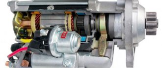
Starter 5712.3708:
1 – cover from the collector side; 2 – collector; 3 – stator pole (permanent magnet); 4 – armature core; 5 – armature shaft support; 6 – satellite; 7 – drive (central) gear; 8 – carrier; 9 – sun wheel; 10 – drive ring; 11 – drive shaft; 12 – restrictor ring for gear travel; 13 – drive gear; 14 – overrunning clutch; 15 – drive shaft support; 16 – satellite axis; 17 – gasket; 18 – lever bracket; 19 – drive lever; 20 – drive side cover; 21 – traction relay anchor; 22 – relay pull-in coil; 23 – relay holding winding; 24 – traction relay rod; 25 – traction relay core; 26 – contact plate; 27 – traction relay; 28 – contact bolts; 29 – bracket; 30 – brush holder; 31 – insulated brush; 32 – armature shaft.
Poles 3 (see figure), which are permanent magnets, are attached to the steel starter housing. The armature shaft 32 rotates in two metal-ceramic bushings installed in the cover 1 on the commutator side and in the shaft support 5. Rotation from the armature shaft is transmitted to the drive shaft 11 through a planetary gearbox consisting of satellites 6, drive gear 7, carrier 8 and sun wheel 9. An overrunning clutch 14 with drive gear 13 is installed on the drive shaft. A traction relay 27 is attached to the starter housing.
Starter connection diagram:
1 – starter; 2 – battery; 3 – generator; 4 – mounting block; 5 – ignition switch (lock); P1 – pull-in winding of the traction relay; P2 – holding winding of the starter traction relay.
The starter connection diagram is shown in Fig. higher. When the starter is turned on, the voltage from the battery through the ignition switch is supplied to both windings of the starter traction relay (retractor P1 and retainer P2). After closing the contacts of the traction relay, the retractor winding is turned off.
Source
Article number and approximate price for the original VAZ 2115 starter
The original VAZ 2115 starter has the internal factory marking 423.3708. For the carburetor version of the car on sale, the unit has article number 2108370801006. Its price is 2,500 rubles.
On VAZ 2115 cars that have an injector, an improved starter is used. It has a planetary gear and provides more stable rotation of the crankshaft. The unit goes on retail sale with article number 21130370801000. Its cost starts from 5,500 rubles.
Starter
29.3708 , 423.3708 or 5712.3708 can be installed on vehicles .
All three starters are a DC electric motor with mixed excitation and an electromagnetic two-winding traction relay. The installation dimensions of the starters are the same. Starters differ in the design of the commutator unit and the drive.
The starter 29.3708 has an end-type commutator, the starter 423.3708 has a cylindrical one, otherwise they are almost the same. Starter 5712.3708 is equipped with a planetary gearbox in the drive.
The main difference between these starters and traditional starters used on other cars is the absence of support for the end of the armature shaft in the cover on the drive side. The support is a bushing pressed into the clutch housing.
Technical characteristics of the starter 29.3708 (423.3708)
Rated power, kW…..1.3 Current consumption at maximum power, A, no more than…..260 Current consumption in a braked state, A, no more than…..500 Current consumption at idle, without relay, Ah, no more…..60
Starter 29.3708 (the design of starter 423.3708 is similar, differs by a cylindrical commutator and a steel drive lever): 1 – restrictor ring; 2 – drive gear; 3 – overrunning clutch roller; 4 – overrunning clutch; 5 – drive lever; 6 – drive side cover; 7 – relay anchor; 8 – relay winding; 9 – contact plate; 10 – relay cover; 11 – contact bolts; 12 – collector; 13 – brush; 14 – cover from the collector side; 15 – casing; 16 – body; 17 – starter pole; 18 – anchor; 19 – drive ring.
In housing 16 (see figure above) four poles 17 with excitation windings are fixed, three of which are series and one is shunt. The body 16 and covers 6 and 14 are tightened with two bolts (for starter 423.3708 - with studs). The armature 18 is equipped with an end-mounted (cylindrical for the starter 423.3708) manifold 12. The rear end of the armature shaft rotates in a metal-ceramic bushing pressed into the cover 14, and the front end in a bushing pressed into the clutch housing.
Technical characteristics of starter 5712.3708
Rated power, kW…..1.55 Current consumption at maximum power, A, no more than…..375 Current consumption in a braked state, A, no more than…..700 Current consumption at idle, without relay, Ah, no more…..80
Starter 5712.3708: 1 – cover on the manifold side; 2 – collector; 3 – stator pole (permanent magnet); 4 – armature core; 5 – armature shaft support; 6 – satellite; 7 – drive (central) gear; 8 – carrier; 9 – sun wheel; 10 – drive ring; 11 – drive shaft; 12 – restrictor ring for gear travel; 13 – drive gear; 14 – overrunning clutch; 15 – drive shaft support; 16 – satellite axis; 17 – gasket; 18 – lever bracket; 19 – drive lever; 20 – drive side cover; 21 – traction relay anchor; 22 – relay pull-in coil; 23 – relay holding winding; 24 – traction relay rod; 25 – traction relay core; 26 – contact plate; 27 – traction relay; 28 – contact bolts; 29 – bracket; 30 – brush holder; 31 – insulated brush; 32 – armature shaft.
Poles 3 (see figure), which are permanent magnets, are attached to the steel starter housing. The armature shaft 32 rotates in two metal-ceramic bushings installed in the cover 1 on the commutator side and in the shaft support 5. Rotation from the armature shaft is transmitted to the drive shaft 11 through a planetary gearbox consisting of satellites 6, drive gear 7, carrier 8 and sun wheel 9. An overrunning clutch 14 with drive gear 13 is installed on the drive shaft. A traction relay 27 is attached to the starter housing.