Minus control
The above translated diagrams are perfect for use in a car. However, the complexity of some electrical circuits lies in the fact that some of the contacts are connected to the positive, and some to the negative (common wire or body). To control the above circuit by minus power, it needs to be slightly modified. The transistor needs to be replaced with a p-channel one, for example IRF9540N. Connect the negative terminal of the capacitor to the common point of three resistors, and connect the positive terminal to the source of VT1. The modified circuit will have power with reverse polarity, and the control positive contact will be replaced by a negative one.
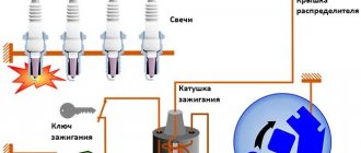
The diagram for this ignition was made based on the recording of a fellow on board. I'm good with soldering irons, but I'm not good with circuits...
Let's return to the diagram; the diagram is very popular on the Internet, therefore it has been tested more than once, but there is one thing - it has one thing that I don’t need - control by plus from the ignition switch and dimensions. I don’t want to crash into the ignition, I just did it by throwing out the same control element from the circuit and setting the resistor that is responsible for the ignition speed to be adjustable (R2* - correction nominal 100 kOhm, ).
What do you need
To properly assemble a soft ignition module for LEDs, you will need a set of the following tools and materials:
- Soldering station and set of consumables (solder, flux, etc.).
- A fragment of a textolite sheet for creating a board.
- Housing for placing components.
- The necessary semiconductor elements are transistors, resistors, capacitors, diodes, ice crystals.
However, before you start making your own soft start/damping unit for LEDs, you need to familiarize yourself with the principle of its operation.
The image shows a diagram of the simplest model of the device:
It has three working elements:
- Resistor (R).
- Capacitor module (C).
- LED (HL).
A resistor-capacitor circuit based on the RC delay principle essentially controls the ignition parameters. So, the greater the value of resistance and capacitance, the longer the period or the smoother the switching on of the ice element occurs, and vice versa.
Recommendation! At the moment, a huge number of soft ignition block circuits for 12V LEDs have been developed. They all differ in their characteristic set of pros, cons, level of complexity and quality. There is no reason to independently manufacture devices with extensive circuit boards using expensive components. The easiest way is to make a module on one transistor with a small connection, sufficient for slow turning on and off of an ice light bulb.
Schematic elements
The main control element is a powerful n-channel MOS transistor IRF540, the drain current of which can reach 23 A, and the drain-source voltage can reach 100V. The circuit solution under consideration does not provide for the operation of the transistor in extreme modes. Therefore, it will not need a radiator.
Resistance R2 is responsible for the smooth ignition of the LEDs. Its value should be in the range of 30–68 kOhm and is selected during the setup process based on personal preferences. Instead, you can install a compact 67 kOhm multi-turn trimmer resistor. In this case, you can adjust the ignition time using a screwdriver.
Resistance R3 is responsible for the smooth fading of the LEDs. The optimal range of its values is 20–51 kOhm. Instead, you can also solder a trimmer resistor to adjust the decay time. It is advisable to solder one constant resistance of a small value in series with trimming resistors R2 and R3. They will always limit the current and prevent a short circuit if the trimming resistors are turned to zero.
Resistance R1 is used to set the gate current. For the IRF540 transistor, a nominal value of 10 kOhm is sufficient. The minimum capacitance of capacitor C1 should be 220 µF with a maximum voltage of 16 V. The capacitance can be increased to 470 µF, which will simultaneously increase the time for complete switching on and off. You can also take a capacitor for a higher voltage, but then you will have to increase the size of the printed circuit board.
On what principle does the circuit work?
For an inexperienced master, the scheme for smooth ignition and attenuation of LEDs may seem complicated, but it is not. In addition to its simplicity, it is distinguished by its reliability and low implementation costs.
Fig. 1 – diagram of smooth combustion of diodes.
First, current is supplied to the second resistor to charge capacitor C1 . VT1 opens smoothly . Current is supplied to the gate through the first resistor. This provokes an increase in potential (positive) on the field-effect transistor (its drain), due to which the LED turns on smoothly.
When the shutdown occurs, the capacitor will gradually discharge through resistors R1 and R3 . The discharge rate is determined by the value of the third resistor.
Driver repair
First of all, check the fuse, if there is one. The device should show zero resistance. This can be done without removing the fuse from the board. Did the device show infinitely high resistance? Replace the fuse and plug in the lamp to test. Is it glowing? The renovation is complete. If the fuse is OK, we continue the repair. Check the diode bridge. You can find out in detail how to do this here.
Is the diode bridge working? Then unsolder the smoothing electrolytic capacitor and ring it. If the capacitor is working properly, then at the initial moment of continuity the multimeter will show a small resistance, which will grow before our eyes until it goes to infinity.
If the driver is simple, as often happens, then all these manipulations will certainly lead to success and completion of the repair. If the driver is more complex, then all you can do is ring the remaining electrolytic capacitors and diodes. It is easier to completely unsolder capacitors; only one terminal of a diode can be unsoldered. To make it lose contact with the board, it is enough to lift the device with a needle or tweezers.
If everything is in order here, then, alas, for further more complex repairs you will have to use the help of a qualified electronics engineer.
Is it possible to do it yourself?
You can make the payment according to the scheme described above on your own. But, if you have no experience working with transistors, LEDs and resistors, it is better to purchase a unit in a store. Do-it-yourself assembly will cost much less. If you know all the details, the work will take no more than 1 hour. To do this, you should know how to select the necessary elements and have the equipment to make high-quality connections.
What you need for work
To make a device for smooth ignition of LEDs with your own hands, you will need the following:
- solder and soldering iron;
- LEDs;
- resistors;
- capacitor;
- transistors;
- housing to accommodate the necessary elements;
- To create a board you need a piece of textolite sheet.
Fig. 2 – textolite sheet for soldering.
The recommended capacitor capacity is 220 mF. Voltage no more than 16V. Resistor values:
- R1 – 12 kOm;
- R2 – 22 kOm;
- R3 – 40 kOm.
When assembling the block, it is advisable to use an “IRF540” field-effect transistor.
Step-by-step DIY instructions
To create a block with smooth ignition, the master must be able to solder and know the operating principle of the circuit and each of its elements. The first stage is making the board. First, you need to mark the boundaries on the PCB. After this, you can start cutting the sheet along the contours. Next, the workpiece should be plastered using sandpaper (P800-1000 grit).
The next step is to print the circuit (layer with tracks). A laser printer is used for this. Such a printable diagram can be found on the Internet. An A4 sheet is glued to glossy paper (for example, from a magazine) with masking tape. Then you should start printing the image.
Fig. 3 – diagram after printing.
The diagram is glued to the sheet using heating with an iron. To allow the board to cool down, place it in cold water for a few minutes and then remove the paper. If it does not peel off immediately, it needs to be done gradually, peeling off with your fingers.
Now you will need double-sided tape to glue the board to foam plastic of the same size and place it in a ferric chloride solution for 5-7 minutes. In order not to overexpose the board, you need to periodically take it out and look at its condition. To speed up the etching process, you can sometimes shake the container with liquid. When excess copper is removed, the board must be washed in water.
Fig. 4 – board in ferric chloride solution.
The next step is cleaning the paths with sandpaper. Next, you can start drilling holes to install the board elements. Drills with a diameter of up to 1 cm are suitable for this. Next, the board needs to be tinned. To do this, it can be lubricated with flux, and then tinned with a soldering iron. To avoid overheating or breaking the circuit, the soldering iron must be constantly in motion.
Fig. 5 – prepared board for installation of elements.
The next stage is the installation of elements according to the diagram. To make it clearer, you can print out the same diagram on paper, but with all the necessary symbols. After soldering, it is necessary to completely get rid of the flux. To do this, the board can be wiped with solvent 646. Then it can be cleaned with a toothbrush. When the block has dried thoroughly, you should begin checking. To do this, a permanent plus and minus must be connected to the power supply. At the same time, you should not touch the control plus.
Fig.6 – checking the correct operation of the board.
Instead of LEDs, it is better to use a multimeter to check. If voltage occurs, it means the board is shorting. This may be due to flux residue. To get rid of the problem, just clean the board again. If there is no voltage, the unit is ready for use.
Buy or make it yourself
The first question that arises when it is necessary to include LEDs in the standard lighting module circuit is whether to do it yourself or buy it. Of course, it’s easier to buy a ready-made block with the specified parameters. However, this method of solving the problem has one significant drawback - the price. If you make it yourself, the cost of such a device will decrease several times. In addition, the compilation process does not take much time. In addition, there are proven options for the device - all that remains is to purchase the necessary components and equipment and connect them correctly, according to the instructions.
Note! LED lighting is widely used in automobiles. For example, these could be daytime running lights and interior lighting. The inclusion of a block for smooth ignition of LED lights allows, in the first case, to significantly extend the service life of the optics, and in the second, to prevent the driver and passengers from being blinded by the sudden switching on of an incandescent lamp in the cabin, which makes the lighting system visually more comfortable.
Smooth load switching on and off
Probably many people wanted to add something new to their car, today I will tell you how to do this without special costs and technical changes in the design of the car. The device that I want to present to you today is not a large circuit for adjusting the startup and shutdown of the load, in our case, lighting fixtures, interior lighting, dashboard lighting, etc. Our device will allow you to smoothly turn on and off any of the listed loads. Agree, it’s much more pleasant when, when you turn on the ignition, we see not a sharp switching on of the dashboard backlight, but a smooth ignition. The same can be said about interior lighting and lighting fixtures. Let's move on from words to action and before starting assembly, I suggest you familiarize yourself with the diagram:
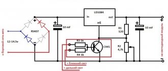
First, I’ll tell you how it connects. We need to supply VCC+ with a constant 12 V from the battery, which will power our load. We connect to REM those 12 V that appear after turning on the ignition, it is they that will initiate ignition and when they disappear, the circuit will turn off the lighting. Accordingly, we connect our load (in my case, LEDs) to the LED+ LED- contacts. I used BC817 (analogue of KT503V) as transistor T1; I took IRF9540S as T2. If you want to increase the ignition time, you need to increase the R2 value; to decrease it, lower it accordingly. To control the damping time, a similar operation must be done with resistor R3. Now you can proceed to assembly. To reduce the size of the device, I used surface mounting. Here is the entire set of elements that I needed:
The boards were manufactured using “LUT” technology from single-sided PCB.
We finally got such a compact device that can add aesthetics to our car.
Expenses: 1. Resistors 0.25 rubles. x4 = 1 RUR 2. BC817 = 3 RUR. 3. IRF9540S = 35 rubles 4. Capacitor 8 rubles 5. Terminals 21.5
Result: For only 70 rubles. we get quite an interesting device. PS Video of the device in action:
Methods for implementing soft start
Before deciding on ways to implement a soft launch, it is necessary to find out how UVPLs work. The principle of operation of devices of this type is based on the ability to first lower and then gradually increase the voltage to the optimal value. The device is connected to the wire gap between the lamp (lamp) and the switch.
When voltage is applied, its value increases due to soft start circuits. They can be assembled using transistors, triacs or thyristors using PIR (phase-pulse regulator) circuits. The rate of voltage increase can vary within a few seconds: much depends on the circuit in which the device was assembled. The load power most often does not exceed 1400 W.
power unit
The protection unit acts as a device that ensures smooth startup. Using the device simultaneously with the lamp allows you to gradually reduce the voltage supplied to the lighting device. In this case, the tungsten filament does not experience much stress, which allows it to prolong its service life.
As electrical current passes through the block, the voltage drops (from 220V to 170V). The speed varies within 2-4 seconds. Using the protection unit as intended leads to a reduction in light flux by 50-60%. Uniel Upb-200W-BL devices can withstand up to 220 V, so it is necessary to connect light bulbs of the same power to them.
The device can be installed next to switches or lighting devices.
Soft start device
The mechanism of operation of the device for smooth switching on of incandescent lamps (UPVL) is the same as that of protective blocks. The device has a significant advantage - its small size, so it can be installed in a socket box (behind the switch), inside a distribution box and a ceiling lamp (under the hood). The UPVL connection must be carried out sequentially, starting from connecting the device to the phase conductor.
Dimming
Dimmers have the ability to regulate electric current, so these devices are often installed in residential areas. The devices change the brightness of the light produced by halogen, LED or incandescent lamps.
A rheostat or variable resistor is considered the simplest dimmer. The device was invented in 1847 by Christian Poggendorff. With its help, you can regulate the strength of electric current and voltage. The device consists of several parts:
- conductor;
- resistance regulator.
The resistance changes smoothly. To reduce the brightness of the light, the voltage is reduced. In this case, the values indicating current strength and resistance will be high, which will cause overheating of the lighting fixture.
Popular articles About how to make a matchstick scarecrow! the easiest way to make this device
Dimmers also include autotransformers. These devices have a fairly high efficiency. The voltage is supplied undistorted, the optimal frequency is no more than 50 Hz. A significant disadvantage of an autotransformer is its heavy weight. To manage them, a person must make every effort.
The electronic version is the simplest and most accessible device with which you can control the current strength. The main part of the compact device is a switch (key), which is controlled by thyristor, triac and transistor semiconductors.
There are several ways to adjust the dimmer:
- along the leading edge;
- along the trailing edge.
The voltage supplied to incandescent lamps can be adjusted in both ways.
Advantages and disadvantages of dimmers
The positive qualities of the devices include:
- Comfortable environment for events. The atmosphere can be lit with bright lamps, or for a quiet movie night the lighting can be dimmed.
- Energy consumption is reduced by controlling a group of lamps, which can be easily turned off if necessary.
- The service life of lighting devices increases.
- Multifunctionality of the device - on, off, brightness adjustment.
- Control can be carried out remotely.
- Installation allows you to avoid installing additional lighting sources.
Despite the extensive list of advantages, the devices have disadvantages:
- The mechanism will break if the device is subjected to heavy loads.
- Dimmers are sensitive to temperature changes and fail due to overheating.
- Not compatible with all types of lamps.
Connecting a dimmer to LEDs with your own hands
To connect the dimmer yourself, you only need the purchased device, a special torque wrench and any convenient cutting tool for stripping wires.
Step-by-step instructions consist of three stages:
- Before starting any installation work, be sure to turn off all electricity in the house.
- Next, you should strip the wires on the device and connect them in such a way that the phase wire is installed in the terminal called L, and the second is connected to the connector called N.
- At the final stage, these wires should be clamped and all existing bolts should be tightened, putting on a special frame.
The cost may depend on the type of model and the availability of all additional functions. More expensive models boast an extensive list of various auxiliary options that allow you to use this device with the greatest comfort. The price varies from 100 to 1000 rubles. Models with remote control will cost you much more.
What LEDs are connected to 12 volts?
To briefly answer the question posed as a subtitle, the answer will be: none! To a non-specialist, such an answer will seem paradoxical, because there are LEDs on sale that, as sellers claim, are designed to be powered by a 12-volt source.
Let us undertake to assert that only LED-based products can be designed for a specific voltage. It is not correct to talk about a specific LED operating voltage. This is due to the physical processes occurring in it when light is emitted.
The main characteristics of these processes are the operating current and the maximum permissible current of the device. Reference books and datasheets indicate the voltages on the LEDs when operating current flows. These values are used for calculating LED designs, and not for selecting a power source.
By the way, the voltage in operating mode only ranges from 1.5 V to 3.5 V. The value depends mainly on the color of the emitted LED. Lower voltages drop on red LEDs; higher values are considered super-bright. Commercially available 12 volt light emitting diodes are not isolated devices.
Twelve-volt LEDs are matrices consisting of several light-emitting diodes. Matrices are LED assemblies assembled from chains of sequentially connected devices.
Each matrix has several chains that are connected in parallel to each other. When they say that an LED is designed for twelve volts, they mean that the voltage drop across a series chain of them when operating current flows is approximately 12 V.
Smooth switching on of LEDs with your own hands
Do-it-yourself smooth switching on and dimming of LEDs
I think everyone understands what smooth switching is, or otherwise the ignition of LEDs.
Let us examine in detail the smooth switching on of LEDs with our own hands.
The LEDs should not light up immediately, but after 3-4 seconds, but initially not blink or light up at all.
Device diagram:
Components:
■ Transistor IRF9540N ■ Transistor KT503 ■ Rectifier diode 1N4148 ■ Capacitor 25V100µF ■ Resistors: - R1: 4.7 kOhm 0.25 W - R2: 68 kOhm 0.25 W - R3: 51 kOhm 0.25 W - R4: 10 kOhm 0.25 W ■ Single-sided fiberglass and ferric chloride ■ Screw terminal blocks, 2 and 3 pins, 5 mm
You can change the ignition and decay time of the LEDs by selecting the value of resistance R2, as well as selecting the capacitance of the capacitor.
Using a utility knife, I made grooves along the marked lines, then sawed them out with a hacksaw and sharpened the edges with a file. I also tried using metal scissors - it turned out to be much easier, more convenient and dust-free.
Next, sand the workpiece under water with P800-1000 grit sandpaper. Then we dry and degrease the surface of the board with 646 solvent using a lint-free cloth. After this, it is not advisable to touch the surface of the board with your hands.
Next, using the SprintLayot program, open and print the diagram on a laser printer. You only need to print the layer with tracks without markings.
To do this, when printing in the program, at the top left in the “layers” section, uncheck unnecessary boxes. Also, when printing, in the printer settings we set high definition and maximum image quality.
Using masking tape, glue a glossy magazine page/glossy photo paper (if their size is smaller than A4) onto a regular A4 sheet and print our diagram on it. I tried using tracing paper, glossy magazine pages and photo paper.
Now we warm up the textolite and attach our printout. Then use an iron with good pressure to iron the board for several minutes.
Now let the board cool completely, then put it in a container of cold water for a few minutes and carefully remove the paper from the board. If it doesn’t come off completely, then roll it up slowly with your fingers.
Then we check the quality of the printed tracks, and touch up the bad places with a thin permanent marker.
The etching time depends on many parameters, so we periodically remove and check our board. We use anhydrous ferric chloride, dilute it in warm water according to the proportions indicated on the package.
To speed up the etching process, you can periodically shake the container with the solution.
After the unnecessary copper has been removed, we wash the board in water. Then, using a solvent or sandpaper, remove the toner from the tracks.
Next you need to tin the board. There are many different ways, I decided to use one of the simplest and most accessible. Using a brush, we lubricate the board with flux (for example LTI-120) and tin the tracks with a soldering iron. The main thing is not to keep the soldering iron tip in one place, otherwise the tracks may come off due to overheating. We take more solder onto the tip and move it along the path.
Now we solder the necessary elements according to the diagram. For convenience, in SprintLayot I printed out a diagram with symbols on plain paper and, when soldering, checked the correct arrangement of the elements.
After soldering, it is very important to completely wash off the flux, otherwise there may be shorts between the conductors (depending on the flux used). First, I recommend thoroughly wiping the board with 646 solvent, and then rinsing it well with a brush and soap and drying it. Result:
Result:
Features of the circuit with time settings
To be able to independently adjust the duration of switching off and switching on, resistors are added to the circuit.
Fig. 7 - circuit with added resistors R4 and R5.
To smoothly turn on the LEDs, it is recommended to use resistors R3 and R2 of small values. The parameters of resistors R4 and R5 make it possible to control the speed of attenuation and switching on.
We recommend watching a series of thematic videos.
DIY crafts for car enthusiasts
Simple electrical tuning of a car using LEDs that flash on and off smoothly. Domestic cars are produced with the average consumer in mind. Many car enthusiasts are not happy with this, so they are trying to improve this car. First of all, this concerns the lighting of the dashboard and interior.
You can assemble a device for continuously adjusting the LED backlight yourself. It’s easy to find an interesting diagram on the Internet.
Without any doubt, the simplest and most reliable circuit is a field-effect transistor. Let's take a closer look.
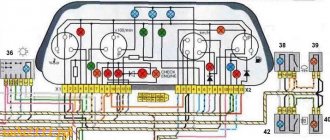
Instrument lighting.
When they talk about upgrading the dashboard, they mean electrical tuning, which allows you to make it unique using LEDs.
A little about the operation of the circuit.....:
After turning on the ignition, the circuit is powered with a voltage of +12 V and switches to standby mode.
When the dimensions are turned on, the control voltage +12 V is supplied to the KT 503 transistor through a chain consisting of diode D2 and resistor R1. The transistor opens. Electrolytic capacitor C1 is charging.
A smoothly increasing voltage is supplied to field-effect transistor VT1. It opens smoothly and gradually increases the output voltage to the LEDs. They burn smoothly.
When the dimensions are turned off, the control voltage is removed and the transistor KT 503 is closed. The electrolytic capacitor C1 is smoothly discharged through R3. Consequently, the voltage across transistor VT1 decreases, and hence the output voltage.
As the capacitor discharges, the LEDs go out.
When the capacitor is completely discharged, the circuit again goes into standby mode, in which almost no current is consumed.
The load of transistor VT1 can be an LED assembly or an LED strip. The IRF 9540 transistor can handle loads up to 140 W.
The following adjustments are allowed in the diagram:
Interior lighting
Smooth interior lighting has its advantages:
The LED backlight turns on after the limit switches on the doors are activated.
The diagram looks like:
Unlike the previous circuit, the control voltage here is –12 V coming from the limit switches.
Compared to the previous one, individual elements have been removed from the circuit: transistor KT 503, diode D2 and resistor R1, but the operating principle is the same.
Schemes in .lay format -
Circuit assembly
The circuit elements are placed on a printed circuit board, which is manufactured in a certain sequence:
1. Prepare a textolite plate. Its size depends on the number of elements and their location. The cut plate must be treated with fine sandpaper and degreased.
2. Using the Sprint Layout program, draw the future board. To print the picture, a laser printer is used in high definition and image quality mode.
The program selects a mode in which only the layer with tracks without markings will be printed. The drawing is printed onto a glossy magazine page or photo paper.
3. Apply the printout to the heated PCB plate and press it with a hot iron. We hold the iron for several minutes.
4. After cooling, lower the plate into cold water and remove the paper from the surface.
5. In the prepared ferric chloride, lower the plate attached to a piece of polystyrene foam. During etching, you can remove and monitor the board.
6. Wash the etched plate in water and clean the tracks with solvent or sandpaper.
7. Drill holes in the finished board for mounting the elements. 0.6 mm drills are used.
8. We service the board. The most affordable way is to coat the board with flux with a brush and tin it with a soldering iron.
It is important not to overheat the tracks so that they do not peel off
9. Install the circuit elements on the board and solder them.
10. At the end of the work, it is necessary to clean the board from any remaining flux. A clean board will have no shorts between tracks.
As a result of the consideration, it should be noted that the described schemes are successfully used not only for electrical tuning of a car. They are often used with various devices that have +12 V power.
Author; Arseny St. Petersburg, Russia
Popular;
- Delay for turning on the low beam or DRL for 8-10 seconds, diagram
- Simple electronic turn signal relay for lamps or LEDs, diagram
- Simple voltage regulator on LM317, circuit
- Smooth on and off DRL
- Converter for charging capacitors
- Smooth ignition of headlights or LEDs on a microcontroller
- Simple driver for LEDs
- Battery protection circuit from deep discharge
Main conclusions
Smooth ignition of LED-based lamps is popular in automatic lighting. In addition, the slow switching on of the ice elements allows you to extend their service life, regardless of the installation location. You can buy such a device or make it yourself. In the latter case, it will cost much less. For assembly you will need the following materials and tools:
- Soldering iron with soldering accessories.
- The basis for the board, for example, a piece of PCB.
- Housing for fastening elements.
- Resistors, transistors, diodes, capacitors and other semiconductor elements.
The mechanism of the soft ignition device for LEDs works on the principle of delay that occurs in the resistor-capacitor circuit. In this case, there are two main schemes - the simplest and with the ability to adjust the ignition time. The latter differs from the first by the presence of two resistors with controlled resistance. The higher its value, the longer the slow start period, and vice versa.
If you have experience assembling a smooth ignition circuit for LEDs, reviewed or other versions, be sure to share your useful experience in the comments.
In some cases, it is necessary to implement a circuit for smoothly turning on or off an LED. This solution is especially in demand in organizing design solutions. To implement the plan, there are two solutions. The first is to buy a ready-made ignition unit in a store. The second is making a block with your own hands. In the article, we will find out why it is worth resorting to the second option, and also analyze the most popular schemes.
Features of connecting LEDs
In most cases, plug-in LEDs require current limiting using resistors. But sometimes it is quite possible to do without them. For example, flashlights, keychains and other souvenirs with LED bulbs are powered by directly connected batteries. In these cases, the current limitation occurs due to the internal resistance of the battery. Its power is so low that it is simply not enough to burn the lighting elements.
However, if connected incorrectly, these light sources burn out very quickly. A rapid drop in the brightness of the glow is observed when normal current begins to act on them. The LED continues to glow, but it can no longer fully perform its functions. Such situations occur when there is no limiting resistor. When power is applied, the lamp fails in just a few minutes.
One of the options for incorrect connection to a 12-volt network is to increase the number of LEDs in the circuits of more powerful and complex devices. In this case, they are connected in series, based on the battery resistance. However, if one or more light bulbs burn out, the entire device fails.
There are several ways to connect 12 volt LEDs, the circuit of which allows you to avoid breakdowns. You can connect one resistor, although this does not guarantee stable operation of the device. This is due to significant differences in semiconductor devices, despite the fact that they may be from the same batch. They have their own technical characteristics, differing in current and voltage. If the current exceeds the rated value, one of the LEDs may burn out, after which the remaining light bulbs will also fail very quickly.
LED strips
An LED strip is a chain of connected LEDs. They are connected for a reason; for example, a regular 12V strip consists of segments of 3 LEDs each. The segments are connected to each other in parallel, that is, each receives a common 12 Volts. Inside the segment, the LEDs are connected in series, and the current on them is limited by a common resistor (there can be two for more efficient heat removal):
Thus, it is enough to simply apply 12V from a voltage source to the tape and it will glow. Simplicity and convenience come at the price of efficiency. Simple math: three white LEDs, each needs one
3.2V, a total of 9.6V. We connect the tape to 12V and understand that 2.5V simply goes into heat on resistors. And this is in the best case if the resistor is selected so that the LED lights up at full brightness.
Connect to Arduino
Everything is very simple here: see the previous lesson on controlling a DC load. It can be controlled via a relay, transistor or solid state relay. We are most interested in smooth brightness control, so I will duplicate the circuit with a field-effect transistor:
Of course, you can use a Chinese mosfet module! By the way, the VCC pin does not need to be connected; it is not connected anywhere on the board.
KIA Spectra “CINΣɌO STAƝƝUM” › Logbook › ► Smooth ignition/fading of LEDs (diagram)
Greetings, dear friends!
Regular readers probably remember the entry in my blog asking for help figuring out the smooth ignition circuit. I would like to briefly remind you what the problem was. Then, almost a month ago, I soldered everything according to the diagram found in the vastness of Drive, but smooth ignition, unfortunately, did not work as it should. Before they started to flare up smoothly, the diodes blinked dimly once (sometimes they just lit dimly) and then the smooth start just began. The LEDs should not light up immediately, but after 3-4 seconds, but initially not blink or light up at all. I tried to assemble the circuit both on a circuit board and without a board at all - but the diodes still blinked dimly. I then tried many different options, but could not get it to work correctly.
After reading a bunch of forums and talking with many people, I finally came to the conclusion that the diagram is incorrect, a stump of a correct working complete scheme. I would like to note that the “chopped off” circuit can only smoothly ignite the diodes (and even then with blinking), but there is no smooth decay. I also wanted to thank Tim
for the advice!
So, now I’ll explain what the error was in the circuit, because of which I spent more than a month fiddling with making the soft ignition board. Since I am quite far from radio engineering, I will explain it in simple language. In the correct complete circuit, the line connected to the “constant minus” is broken by the installed transistor KT503 and closes only after a positive control signal is applied to the transistor. That is, it turns out that the soft ignition board is constantly connected to the “plus” and “minus” (“minus” is common to the LEDs and to the board elements), but the “minus” “goes” to the LEDs, but not to the board elements (since the line is broken by transistor KT503). In the “chopped off” circuit, for some reason this transistor was removed altogether, but the minus remained common, which is why the circuit did not work quite correctly, and there was no smooth attenuation.
Principle of operation of the circuit (information from the Internet): The control “plus” is supplied through a 1N4148 diode and a 4.7 kOhm resistor to the base of the KT503 transistor. At the same time, the transistor opens, and through it and the 68 kOhm resistor the capacitor begins to charge. The voltage on the capacitor gradually increases, and then through a 10 kOhm resistor it is supplied to the input of the field-effect transistor IRF9540. The transistor gradually opens, gradually increasing the voltage at the output of the circuit. When the control voltage is removed, the KT503 transistor closes. The capacitor is discharged to the input of the field-effect transistor IRF9540 through a 51 kOhm resistor. After the capacitor discharge process is completed, the circuit stops consuming current and goes into standby mode. The current consumption in this mode is negligible.
The “chopped off” circuit with minor amendments is only suitable for connection with negative control (for example, for interior lighting, where control is from door limit switches). In this situation, you still need to break the “common minus” (“the minus” from the tape is constantly connected to the power supply, the “minus” from the board is the control one). Below are the correct diagrams with “controlling minus and plus”, respectively.
Circuit with control minus:
Circuit with control plus:
This time I decided to make the circuit using the LUT method (laser ironing technology). I did this for the first time in my life, I’ll say right away that there is nothing difficult. For work we will need: a laser printer, glossy photo paper (or a page from a glossy magazine) and an iron.
COMPONENTS: ■ Transistor IRF9540N ■ Transistor KT503 ■ Rectifier diode 1N4148 ■ Capacitor 25V100µF ■ Resistors: - R1: 4.7 kOhm 0.25 W - R2: 68 kOhm 0.25 W - R3: 51 kO m 0.25 W – R4 : 10 kOhm 0.25 W ■ Single-sided fiberglass and ferric chloride ■ Screw terminal blocks, 2 and 3 pins, 5 mm
Schematic diagram of the protection device
The UPVL scheme consists of the following:
- DA1 - phase regulator;
- C1, C2, C3 - capacitors;
- VS1 - triac;
- R1 - resistor;
- SA1 - key;
- VS1 - electrode;
- EL1 - lamp;
- VTA12 - triac.
How is a smooth switching on of light created? DA1 is a thyristor microcircuit with a control circuit consisting of C1 and C2, VS1. R1 limits the current through VS1. The device operates when SA1 is open, C3 is charged and starts the thyristor control circuit. At the output of it, the current will increase until it reaches its rated value. In EL1, the voltage also increases slowly from 6 V to 230 V. The time until the lamp is completely turned on depends on C3. When SA1 is turned off, C3 is discharged to R2, and the voltage gradually drops from 230 V to 0. The period of complete extinguishing of the lamp is directly proportional to the value of R2. C4 and R4 perform the function of protecting the circuit from interference, and HL1 and R3 perform the switch illumination.
Values of C3 μF and response time EL1:
- 47 uF - 1 sec;
- 100 uF - 3 sec;
- 220 uF - 7 sec;
- 470 uF - 10 sec.