REMOVING THE INSTRUMENT PANEL OF VAZ 2114 WITH YOUR OWN HANDS
The need to remove the “torpedo” can arise either quite unexpectedly - due to a breakdown of the stove or radiator, which can only be reached with the panel removed, or as planned - to replace a worn out “torpedo”.
We present to your attention a diagram of the fourteenth dashboard.
Let's look at its components:
- The main part of the structure, which, as a rule, is called the “torpedo” - all the auxiliary elements and components of the dashboard are fixed on it;
- Overlay for the VAZ 2114 panel, on which the air duct openings are located;
- Fixing brackets;
- Plugs;
- Ashtray;
- Right support frame (cross member);
- Right shield covering the wiring cable;
- Instrument panel VAZ 2114;
- Central bracket;
- Left wiring panel;
- Left support frame.
To do all the work at home we will need the following tools:
- Flat and Phillips screwdriver;
- A set of keys;
- Flashlight;
If you first study the theory of how to remove the instrument panel on a VAZ 2114, then the whole job will take you no more than 3-5 hours.
And so, let's move on to step-by-step instructions on how to remove a torpedo on a VAZ 2114 with your own hands.
First of all, it is necessary to remove the shields covering the wiring (in the diagram they are indicated by numbers 7 and 10). Let's start from the left. It can be removed quite simply - use a Phillips screwdriver to unscrew the three fixing screws; Next, remove the right shield - the procedure is the same, only there are 2 more screws in it
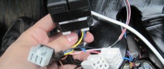
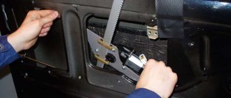
You must remove the screen carefully, since the plastic can damage the wiring located underneath it; Before removing the radio, you must remove the negative terminal from the battery. To dismantle the tape recorder, you need to disconnect the wiring block that connects it to the power supply, acoustics and antenna; Now you need to remove the cigarette lighter and ashtray, do not forget to pull out the light bulb from it; We take out the stove control knobs. To do this, you need to pick them out with a flat screwdriver or a knife, since the handles are connected to the base by grooves; We remove the knob for setting the power mode of the stove; to dismantle it you just need to pull it towards you; On the left and right sides of the instrument panel there are screws with which it is attached to the car interior
Unscrew them with a Phillips screwdriver; We unscrew the screws on the instrument block (speedometer), one of them is located on top, the second is located on the bottom of the block. The cover on the instrument panel can be easily removed after unscrewing the fasteners; We disconnect all wiring connected to the instrument panel. You can remove the arrows from the panel by carefully prying them off with a knife; Let's move on to the steering wheel. To remove the steering wheel on a VAZ 2114, you need to unscrew the bolts that secure the steering column bracket at the top and bottom. To do this you need a key of 8; On the right side of the headlight and rear window heating control buttons there is a plastic plug; you need to remove it and unscrew the screw hidden under it; Next, we dismantle the clamp that holds the heating control unit, after which we pull out the entire cartridge of the unit; We remove all the remaining decorative elements of the “torpedo”: the algorithm is still the same - unscrew the screws under the plugs and dismantle the plastic panels;
To do this, you need to pick them out with a flat screwdriver or a knife, since the handles are connected to the base by grooves; We remove the knob for setting the power mode of the stove; to dismantle it you just need to pull it towards you; On the left and right sides of the instrument panel there are screws with which it is attached to the car interior. Unscrew them with a Phillips screwdriver; We unscrew the screws on the instrument block (speedometer), one of them is located on top, the second is located on the bottom of the block. The cover on the instrument panel can be easily removed after unscrewing the fasteners; We disconnect all wiring connected to the instrument panel. You can remove the arrows from the panel by carefully prying them off with a knife; Let's move on to the steering wheel. To remove the steering wheel on a VAZ 2114, you need to unscrew the bolts that secure the steering column bracket at the top and bottom. To do this you need a key of 8; On the right side of the headlight and rear window heating control buttons there is a plastic plug; you need to remove it and unscrew the screw hidden under it; Next, we dismantle the clamp that holds the heating control unit, after which we pull out the entire cartridge of the unit; We remove all the remaining decorative elements of the “torpedo”: the algorithm is still the same - unscrew the screws under the plugs and dismantle the plastic panels;
If you plan to completely remove the panel from the car, then you need to disconnect all the wires, harnesses and wiring to the backlight bulbs located on the dashboard.
https://youtube.com/watch?v=Ab1W1UaFjJM
Main reasons
Almost all problems related to automotive electrical systems can be solved in approximately the same way. You need to look for a potential or probable cause of malfunctions in the problematic object itself, or understand the system responsible for supplying power.
The situation is exactly the same with devices called brake lights. If they stop working, then you should look for the reason in one of the following points:
- There were problems with the fuse. It has oxidized or completely failed;
- There are faults in the lamps themselves or in one lamp, depending on how many stops are not working;
- The reason lies in the mechanism responsible for turning on the warning signal when the brake is applied;
- In the socket where the stop light is installed, the contacts have oxidized;
- More serious problems appeared related to damage to the wiring.
The brake lights on the VAZ 2114 do not light up: reasons and methods for eliminating them
According to current traffic regulations, driving a car that does not have brake lights is prohibited, and this should be clearly remembered.
True, this rule can be taken into account in practice only when leaving the garage.
But what to do if the feet on the VAZ 2114 fail during the trip? Why not call a tow truck because of such a problem? In fact, this problem can be solved even on the road.
To do this, you only need to have a minimum set of tools:
- multimeter (even the simplest one will do);
- Screwdriver Set;
- sandpaper (for cleaning oxidized surfaces);
- set of wrenches.
In addition, it is good to have a fuse box diagram on hand.
Fuse failure. Broken wires in one of the sections of the circuit. Limit switch faulty. Bulbs burn out. Oxidation of contacts in lamp sockets.
Tail light repair
The most common reason for the failure of a VAZ 2114 rear light is the failure of a flexible printed circuit board or a connector made directly on it with conventional metallization. You can, of course, just buy a new printed circuit board and replace the faulty one with it, but, firstly, for how long?
And secondly, we are not looking for easy ways. So we will try to eliminate this malfunction on our own, at minimal cost and in such a way that it will last forever. Let's start with the connector for connecting the flashlight to the on-board network. It looks something like this:
The connector for connecting the rear light to the on-board network is part of a flexible circuit board and cannot be replaced separately
There are many reasons for this connector to fail. For example, we removed the power supply from the flashlight too often and simply partially erased the traces, which have a very small thickness of copper deposition on the plastic. Another reason is that the conductive paths next to the connector broke due to constant vibration. Well, the most banal thing is that the tracks burned out due to overload or short circuit.
Due to burnout of the conductive tracks of the flexible board, the rear fog lights do not light up
The photo shows a flashlight connector of a different modification, but the meaning of the problem is the same. All these issues can be solved with the help of a soldering iron, mounting wire and a regular six-pin (or more) connector with a mating part.
For repairs you will need this block with a mating part
We clean the connector contacts on the board using a student eraser (not sandpaper - the foil is very thin!) and service them.
We solder the wires from the block onto the tracks, not forgetting to mark them, and fill the soldering area with sealant or a hot glue gun.
Mounting block soldered to the rear light board
We cut off the standard power harness block, and in its place we solder the mating part of the new one. We assemble the flashlight, connect it to the on-board network - and check it. If we haven't messed up the wiring of the pads, then everything will work right away with a bang.
What to do if the tracks are burned out or broken? You can get out of this situation as follows. Immediately after the fracture, we clean the protective varnish from the tracks, tin, and solder the block. It will look like this:
You can solder the header anywhere on the flexible board.
You can, of course, limit yourself to this (until next time), but if you spend a little more time and effort, you can make more serious repairs. Flashlights modified in this way will serve faithfully for many years. Such a repair will save you from the eternal problem of contacts of flimsy standard sockets - this is also a very common malfunction of VAZ 2114 headlights.
To implement this idea, in addition to the six-pin block with a mating part (see above), you will need five cartridges from the VAZ 2106 direction indicators and a dozen terminals for them.
You will need 5 such cartridges and 10 terminals for them
We remove the lamps, standard sockets and flexible printed circuit board from the panel. We place the purchased cartridges in the right places on the panel and mark their centers. Special precision is not required here, the main thing is that each lamp shines into its own “window”. We drill holes according to the diameter of the base parts of the cartridges.
Holes for future cartridges
We insert the cartridges into the holes, mark the mounting holes, drill them, and screw in the screws. Now the cartridges are firmly fixed in the panel.
We secure each cartridge with two self-tapping screws
Using a mounting wire with terminals pressed onto it (you can crimp it with ordinary pliers and solder it to be sure), we assemble a circuit that repeats the layout of a standard flexible printed circuit board. To be sure, the terminals can be insulated with heat-shrinkable tubing, but in principle this is not necessary - the panel on which the cartridges are mounted is plastic. We solder our block to the ends of the wires.
This block will connect the rear light to the on-board network
We solder the mating part of the block to the power supply harness of the lights, having first cut off the old one. We solder it, not twist it together. The twist will oxidize in a week, and problems will begin again - sometimes it burns, sometimes it doesn’t. We insulate the solder joint with heat shrink or cotton (black rag) tape. PVC electrical tape is an extremely bad option. It can unfold over time. This kind of isolation is no good.
Everything is ready, you can connect and check
We admire our work for a couple of minutes, insert the lamps, connect them, check them. Is everything working as expected? We assemble the lantern and connect it.
The lantern is in place, all problems are solved for a long time
LED analog P21W
How to replace lamps
Now let's move on to replacing lamps. Let's start with the interior light built into the trunk lid.
Interior tail light
Open the trunk lid and find the rear part of the lamp from inside it.
The back of the lamp is not covered by anything
We find two latches on top, marked with an arrow in the photo below.
The back cover of the flashlight is secured with two push fasteners
Press the latches and remove the back cover along with the lamps.
Removing the board with light bulbs
It is not necessary to remove the power supply when replacing light bulbs - the length of the power harness will be sufficient for the work.
The one that is closer to the side of the car is the reverse light, closer to the center is the fog light. Since in the photo below the lamp is on the right, the reverse indicator lamp is on the right. It is marked with a red arrow.
The inner rear light has 2 bulbs
The bulbs are of the same type (see above) and are removed in the same way - by turning them counterclockwise. We remove the burnt one and install a new one in its place. We snap the board into place.
Corner lantern
Open the trunk lid again and find a valve on the upholstery that closes the rear part of the lamp. It has Velcro and opens easily. Let's open it.
The corner taillights of the VAZ 2115 are covered with valves cut into the upholstery
In front of us is the back of the flashlight with the power connector sticking out of it.
The power supply sticks out from the back of the flashlight.
We remove the block by simply pulling it in the direction of movement of the car (if the length of the harness is sufficient, the block does not need to be removed).
Removing the power supply
Push the latch outwards with a screwdriver or simply with your hands (it is placed closer to the central axle of the car) and remove the board along with the lamps.
Removing the board with lamps
We have already talked about where the light bulb is. Single spiral on the side - direction indicator. Two double-spiral ones - both dimensions and feet. We remove the burnt one and install a new one. We snap the board into place, connect the connector, and close it with the valve in the upholstery.
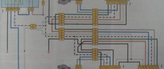
Complete electrical diagram of the VAZ 2114 with decoding
The complete package of electrical equipment of the VAZ 2114 can be divided into two types. The fundamental differences are due to changes in equipment depending on the year of manufacture and equipment of the car. In this case, the entire drawing can be divided into several zones.
- The engine compartment is responsible for providing voltage to sensors and instruments located directly inside the engine compartment.
- Salon compartment. The part is primarily used to connect the front and rear compartments.
- Instrument panel assembly. The pinout is displayed directly on the controls and dashboard. All elements of the on-board network are combined here and connected to buttons or indicators.
- Stern joint. The small module combines chain elements located at the rear of the machine. Typically, the segment is subject to frequent damage, which is due to the constant transportation of goods in the luggage compartment. When moving over obstacles, loads can damage sensitive equipment.
You can also separate small units – these are door units, windshield wipers and others. For ease of perception, each beam is considered separately.
VAZ 2114 instrument panel pinout
The terminals of all vehicle equipment are concentrated here. Due to the fact that the unit is located under the dashboard and is subject to constant condensation or fogging, some users treat it with hot melt adhesive. Even a thin coating can reliably protect the device from water ingress.
Elements are connected to devices or controls:
- 1 – switch key for heated rear glass;
- 2/6 – fog light switches, for rear/front module;
- 3 – plastic block for activating head optics and turn signals;
- 4 – fuse block;
- 5 – wiper mode switch;
- 7 – on-board system indication;
- 8 – supply voltage to the additional harness;
- 9 – dashboard;
- 10 – “male” for powering the on-board computer;
- 11 – terminal to the ignition device;
- 12 – for door wiring;
- 13/14 – fuses;
- 16 – ignition break;
- 17 – stove motor;
- 18 – secondary resistance of the stove;
- 19 – current supply to the ignition unloading relay;
- 20 – protective relay for rear fog lights;
- 21 – starter fuse relay;
- 22 – remote socket for a portable lamp;
- 23 – power supply for the cigarette lighter;
- 24 – for illumination of the glove compartment;
- 25-27 – illuminators;
- 28 – stove switch;
- 29 – tidy lighting with rheostat;
- 30 – stop switch;
- 31/32 – horn/hazard warning switch, respectively;
- 33 – backlight of the stove panel;
- 34 – fuse;
- 35 – protective relay for seat heating elements;
- Ш1/4 – mounting block jumpers;
- X1/2 – dashboard controls;
- A – protective ground output (usually black).
Pinout of rear lights VAZ 2114
Video and repair tips: pinout of the VAZ 2114 rear light board - you are welcome. Your personal assistant in DIY car repairs. How to repair a car yourself at home. We will help you with repairs and repair the car yourself. We know how to restore a car with minimal investment. I have attached video instructions.
Category: Make a car yourself
Laughter on topic: - Yes, my Internet is not only unlimited, it’s also free. - How is that? - Yes, it’s all dad. When the Internet was connected, he and the upstairs neighbors agreed that they would connect together, and they would pay in even-numbered months, and we would pay in odd-numbered months. - Well? - Well, he and the neighbors downstairs agreed that they would be on odd numbers, and we would be on even ones!
Published by Admin: at the request of Anners
The car owner's reasoning: ComfortControlDynamics
Electrical diagram of VAZ-2115
- — block headlights;
- — gearmotors for headlight cleaners*;
- - fog lights*;
- — ambient temperature sensor;
- - sound signals;
- — engine compartment lamp switch;
- — electric motor of the engine cooling system fan;
- — generator;
- — low oil level indicator sensor;
- — washer fluid level sensor;
- — front brake pad wear sensor;
- — wire tips connected to the common windshield washer pump**;
- — windshield washer pump;
- — headlight washer pump*;
- — wire ends for connecting to the rear window washer pump on VAZ-2113 and VAZ-2114 cars;
- — low oil pressure indicator sensor;
- — engine compartment lighting lamp;
- — wire lug for connection to the wiring harness of the engine control system;
- — gear motor for windshield wiper;
- — starter;
- — a block connected to the wiring harness of the ignition system on carburetor cars;
- — coolant temperature indicator sensor;
- — reversing light switch;
- — low brake fluid level indicator sensor;
- - accumulator battery;
- — low coolant level indicator sensor;
- — relay for turning on fog lights;
- — mounting block;
- — brake light switch;
- — plug socket for a portable lamp;
- — hydrocorrector scale illumination lamp;
- — switch for the parking brake indicator lamp;
- — block for connecting a backlight lamp;
- — switch for instrument lighting lamps;
- - Understeering's shifter;
- - hazard warning switch;
- — front seat heating element relay;
- — ignition switch;
- — rear fog light circuit fuse;
- - fuse for the front seat heating elements;
- — door lock circuit fuse;
- — front ashtray illumination lamp;
- - ignition relay;
- - cigarette lighter;
- — glove box lighting lamp;
- — switch for the glove compartment lighting lamp;
- — heater fan electric motor;
- — additional resistor for the heater electric motor;
- — heater fan switch;
- - heater switch illumination lamp;
- — lamp for illuminating the heater levers;
- — gear motors for electric windows of the front doors;
- — power window switch for the right front door (located in the right door);
- — gear motors for locking front door locks;
- — wires for connecting to the right front speaker;
- — gear motors for locking rear doors;
- — wires for connecting to the right rear speaker;
- — door lock control unit;
- — wires for connection to radio equipment;
- — headlight cleaner switch*;
- — rear window heating element switch;
- — relay for turning on the rear fog lights;
- — block for connection to the heating element of the right front seat;
- — rear fog light switch;
- — switch for the heating element of the right front seat;
- — fog light switch*;
- — switch for external lighting lamps;
- — left front seat heating element switch;
- — block for connection to the heating element of the left front seat;
- — wires for connecting to the left front speaker;
- — power window switch for the left front door (located in the left door);
- — power window switch for the right front door (located in the left door);
- — wires for connecting to the left rear speaker;
- — side direction indicators;
- — courtesy light switches on the front door pillars;
- — courtesy light switches on the rear door pillars;
- - lampshade;
- — ceiling lamp for individual interior lighting;
- — block for connecting to the wiring harness of the electric fuel pump;
- — trunk light switch;
- — instrument cluster;
- — trunk lighting lamp;
- — display unit of the on-board control system;
- - trip computer*;
- — block for connecting the wiring harness of the engine control system;
- — rear exterior lights;
- — rear interior lights;
- — pads for connecting to the rear window heating element;
- — license plate lights;
- — additional brake signal located on the spoiler.
Lighting
Since the staff bumper does not have seats, they must be made by yourself. To do this you may need:
- Drill with a drill;
- Electric puzzle;
- File;
- Measuring instruments (tape measure, ruler, etc.);
- Marker;
Removing the front bumper of a VAZ 2114
,installation of PTF in
bumper
, in which there is no room for them. Continuation
On our channel you will always find a solution to your problems that you have when repairing your steel
Installation of fog lights is carried out with the bumper removed. Marking is first done on a bumper that has been cleaned of dirt. The optimal installation location is at the level of the lower air intake, but at some distance from it. It is advisable that the PTF be located strictly under the headlights.
First determine the distance at which the fog lights will be removed from the air intake. Then we'll figure out what size holes to cut. Decorative “glasses” will help with this. They consist of two halves. external (decorative) and internal (fixes the external part and the headlights themselves).
The outer half of the glasses has tabs on the inside to fit into the hole in the bumper. To determine the size of the hole, the dimensions of this mounting protrusion are measured. After we place the markings with the appropriate dimensions on the bumper.
Once the markings are complete, we will continue cutting the holes with an electric jigsaw. After this, the edges of the holes must be adjusted using a file
It is important to make sure that the outer part of the glass fits tightly into the hole
In these holes we fix the fog lights with bolted connections. All that remains is to fix the “glasses” headlights.
After installing the fog lights, we install the bumper on the car. This completes the first stage.
Malfunctions and repairs
To repair a VAZ headlight, it must be removed.
In the case of rear lights, you should replace standard sockets and chips with high-quality ones, and seal the joints with sealant. This will eliminate problems with contacts and improper operation of modules.
If the front lights of the VAZ do not work, then you need to inspect:
- chips and wiring;
- lamps;
- glass condition.
If problems are detected in the wiring, the faulty parts are replaced. Burnt-out light elements are removed and new ones are installed. If glass is broken, it is not difficult to re-glue it with sealant or remove the defect using special glue.
If after all the work the headlights do not shine well, then the optics need to be replaced with new ones. To do this, you need to decide on the manufacturer and purchase a set of suitable lamps.
Construction and operation
Xenon and LED equipment is not installed in VAZ from the factory. The optics of the VAZ 2114 are equipped with several modules using a classic halogen lamp for the main light.
The headlight design of the VAZ 2114 is not complicated or modern. To replace the lamps, the optics do not need to be dismantled, and the beam is adjusted using built-in thumbwheels.
The disadvantages of front optics include the appearance of cracks in the glass due to stones or sudden temperature changes during operation.
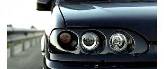
Headlights
On sale there are lensed headlights for the VAZ 2114 for halogen and xenon. Sports modifications are covered with transparent glass with no reflective lines. The internal reflector of the lens is used to form the daw. In such VAZ optics, two separate lamps are used - for the high beam and low beam.
Factory installed front light design:
- block with reflector for low and high beam;
- separate lamp for side lights;
- turn signal made of transparent orange plastic.
A distinctive feature is a glass shield with special lines that direct a beam of light onto the road surface.
When installing modified flashlights, it is necessary to connect additional power, ignition units and adjust the beam position angle. To turn on the high beam using the standard button in the VAZ interior, you need to correctly identify the contacts and apply them to the module.
The advantages of installing sports optics include an increase in the light spot, while the disadvantages are additional manipulations with the wiring and the low quality of the proposed replacement.
Rear optics
If the standard front optics are reliable and of high quality, then the rear lights of the VAZ 2114 are often capricious and do not work properly.
- poor quality of contacts;
- water getting on the board;
- thin plastic.
The VAZ 2115 also suffers from a similar illness and requires constant attention to the rear blocks.
Due to the poor quality of the contact group, the direction indicator, reverse signal or tail light disappears. When the board gets wet, the optics do not work properly and may blink as a brake light instead of a turn signal. Low-quality plastic bends when heated; due to the gaps formed, the flashlight fogs up and the lamps shine dimmer.
Recommendations
Comments 28
And that’s it., finally)) the mounting block turned out to be working, but still left a new one as a spare, because everything on the old glass heating fuses burned out. I replaced the rear boards and harnesses with wire plugs, all the wiring was rotted in the plugs, and the stop on the spoiler was also replaced with a new one, the old one somehow broke along with all the stops for the company.
Total. Stop in spoiler 250 rub. Boards cost 220 rubles each assembled. Flagella 20 RUR, mounting block from disassembly 1000 RUR.
The new stop spoiler is of much worse quality, the factory one was much brighter. The lamps in the new stop are terrible
We got around to replacing the mounting block with a new one. I rearranged everything and ooooopppppaaaa. The feet still don't work)))
To be honest, I don’t know where to dig anymore...
In the meantime, I’m waiting for my salary, I’ve already gotten used to pressing the rear PTF button when braking))) so that no one will correct my ass))) at least somehow attract attention that I’m braking)))
Still, I decided to disassemble the mounting block and the forecast is disappointing, fuse f4, which seems to be used for heating the rear window, the cigarette lighter and somewhere else, melts the board, everything around it is scorched, the board can’t even be reached, the plastic has already melted to it, next to fuse f3 it is is responsible for the brake lights, perhaps the whole reason is this, how reluctant I am to buy a new unit... but I’ll have to go on a hike. So far I have only treated it with liquid electrical insulation before replacing the unit
That's all we have. all 3 brake lights (spoiler) do not work. The light bulbs are intact, the grounds have been cleaned, the boards are in more or less perfect condition, the tracks are intact, the lamp serviceability relay has been replaced with a new one, the frog is working, the frog is receiving power. for a mystic?))))
In short: in the footsteps, today it was the same, two lamps stupidly burned out at the same time. The spoiler most likely has some wiring cut somewhere. Regarding the turn signal: this is a jamb of the board, either change the lights completely, or just start the car, turn on the lights, turn signal and lightly hit the glass with your palm several times until it is fixed (the contact comes off there). Cleaning doesn't help for long.
stripping does not save for very long. If the weather is rainy or winter, then a month at most (
Check the limit switch (frog) under the brake pedal, it may be damaged. Better yet, buy it and replace it right away, the price is reasonable.
I removed the wires from the frog, shorted it out, nothing lights up, I’ll buy a tester, I’ll have to see if there’s any current flowing to it at all
Check the limit switch (frog) under the brake pedal, it may be damaged. Better yet, buy it and replace it right away, the price is reasonable.
There are 12 V on the wires to the frog, so what?) I shorted the wires, everything is quiet. Let's go to the relay then
And if it burns out, the stops don’t burn? It is also responsible for the fact that if they do not light up, it signals or I do not understand its essence correctly
How can I check the relay? With others, it’s clear they click) should this also be?)))
if it’s burnt, you’ll know by the smell)) and you can open it, there are 2 latches on the sides, you can pry them off and the relay housing will come off
The problem with the blinking of the fog lights along with the turn signals was solved by cleaning the contacts of the headlight. My feet don't still burn. I'm looking at the relay
Are both feet missing? Look at the relay for monitoring lamp malfunctions (the largest in the ChYa) when I paralleled the stops with the PTF, the relay burned out from overload, but yours may have just burned out from a bad ground))
Tuning taillights - main options
Tuning tail lights on a VAZ is most often:
- painting rear lights;
- use of tint film;
- installation of LEDs.
The surface is covered with glossy or matte vinyl film. It can be applied completely, partially in a certain place on the glass and removed at any time. Tinting material is produced in different colors and shades. The film has a protective function and can be used to protect the element from mechanical impacts of small stones.
The film is applied to the outer surface of the headlight in stages:
- Wash and dry the headlight unit.
- Wet the surface with soapy water.
- Cut the film to the required size.
- Remove the backing and apply it to the surface of the lampshade.
- Carefully smooth out from the center to the edges.
- Dry with a hairdryer.
- Remove excess film.
Varnish or paint is an economical option, but not always effective if you apply it yourself. To use, you need to wash and dry the lanterns well, then degrease and varnish.
Tinting should not reduce the brightness of lights by more than 15%. Although the traffic rules do not contain clear instructions on tuning rear optics, questions from the inspector may arise.
Tuning LED headlights have increased brightness and clearly define the dimensions of the car. More often, diode strips are used, which are installed around the perimeter of the rear stop.
Using LEDs
To tune the rear lights of the VAZ 2110, installing LEDs and painting the lampshade are most often used. LEDs are mounted in plastic reflectors after dismantling the headlight unit. For the VAZ 2110 it is recommended to choose two colors: red and yellow. The tapes are soldered and placed on the base inside the headlight unit.
To make the light as bright as possible, the base of the headlight is painted black. Tuning procedure step by step.
- Dismantle the headlight, remove the glass, remove the lamps.
- Fill the inside of the block with a thin layer of polyurethane foam.
- Give the foam the desired shape by determining the areas for installing the LED strip.
- Glue the LEDs onto the base inside the headlight.
- Install glass, connect wiring.
When installing LEDs at 6 Volt dimensions, stops and turns at 12 Volt, capacitors are installed, this prevents overheating of the optics.
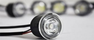
LED characteristics
Modern single LEDs, matrix blocks, diode strips produced by well-known companies are distinguished by their high service life and reliability. Technical characteristics of LED blocks:
- service life more than 4000 hours;
- operate at minimum on-board voltage;
- good light data;
- no overheating occurs;
- are not subject to vibration and mechanical effects;
- variety of colors.
The luminous flux of such lamps does not dazzle the eyes and is visible from a great distance. Availability allows for inexpensive and high-quality repairs.
DIY LED tuning of rear lights
To perform LED tuning of rear lights you will need a minimum set of tools and an LED strip of the required length. Do-it-yourself tuning of rear lights on a VAZ 2110 step by step:
- Disassemble the headlight.
- Pull out the diffuser.
- Paint the reflectors black.
- Prepare the site and glue the LEDs.
- Solder stabilizers and wires from old lamps to the tape.
- Place the reflector on top of the diodes.
- Assemble the tuned spotlights and install in the reverse order.
LED pinout
Before connecting the wires, you need to pinout the LEDs. To make them glow, you need to pass an electric current through them in the direction from the anode to the cathode. To do this, a positive charge must be applied to the anode, and a minus charge must be directed to the cathode.
It is recommended to check the LED strip before installing it on the car.
Do-it-yourself headlight replacement
Replacing headlights on a VAZ 2114 does not require expensive tools. For this work you will need a set of wrenches and screwdrivers.
For convenience, you should prepare the car and materials:
- Wash the body and engine compartment.
- Buy dry wipes.
- Prepare sandpaper to clean contacts or new chips protected from moisture.
To change the front headlight, you need to follow these steps:
- Disconnect the battery terminal.
- Unscrew the four bolts and remove the plastic in front of the radiator.
- Disable the chips from the optics and turn signal.
- Press out the turn signal angle retaining spring.
- Press the plastic fasteners and pull the corner along the direction of the car.
- Unscrew the screws holding the headlight.
- Turn the adjuster rod counterclockwise and disconnect it.
- To remove the eyelashes under the optics, you need to loosen the screws of the bumper near the lamp, bend the corner and unscrew the fasteners.
There is a method for removing the headlight assembly with the “eyelash”. To do this, you need to additionally unscrew the three screws holding the “eyelash” and pull out the block assembly.
Do-it-yourself dismantling of rear lights:
- Disconnect the battery terminal.
- Open the luggage compartment and free up space from unnecessary parts.
- Bend back the soft covering.
- Disconnect the plugs.
- Unscrew the nuts from the studs.
- Remove the reverse sensor.
- Carefully pull the headlight out.
When unscrewing the nuts, do not rush. A part that accidentally falls under the trim will require additional disassembly of the trunk and will take extra time.
Options for replacement
On the assembly line, VAZ cars are equipped with Bosch or Kirzhach headlights. The main difference is the modified design, which provides spot lighting with optics from Bosch. Despite all the advantages, German optics do not sufficiently illuminate the road directly in front of the car. Therefore, it is better to use such headlights in conjunction with fog lights.
Taiwanese manufacturers offer lensed headlights with LED eyelashes, a dark mask and an improved appearance. Lenses configured for xenon have a wide beam and increased brightness. To install such a headlight, you will need to integrate it into the standard wiring. The seats and fasteners are not subject to modification.
Factory VAZ taillights quickly fade and fail. On store shelves you can find a worthy replacement from Taiwan. LED lights are connected to the standard on-board network and operate under the control of an electrical board in a waterproof case. The advantages of the modification include improved brightness, as well as the absence of problems due to water ingress. Installation of lighting does not require intervention in fasteners or electrical connections.
Front
Simple removal of headlights using available tools does not take much time. The part is washed with soapy water, the condition of the reflector is assessed and, if necessary, the protective shield is peeled off. To replace the glass on a headlight:
- Remove the part.
- Place the headlight in a closed box with a hole for a hair dryer.
- Heat the box for 15-20 minutes.
- Remove the part and carefully tear off the melted sealant.
- You can disassemble the stuck shield using a flat-head screwdriver.
Before reassembly, the surface is cleaned, new glue is applied and the glass is carefully applied.
When installing new optics, you should use the included electrical diagram and connect the wires correctly.
When dismantling the VAZ 2115, fabric gloves are used. The headlights should be removed carefully so as not to damage the paintwork on the bumper or fenders.
Rear
Replacing the rear lights of a VAZ 2114 does not require reconnecting the plugs and power. Ready-made LED lights are offered in different designs, but correspond to the factory fastening method.
Checking the plugs for corrosion will prevent possible malfunctions and loss of contact.
When the rear fog lights are turned on, an orange icon is displayed on the instrument panel, as is the case with factory optics.
Installation and connection of front and rear PTFs on VAZ 2113, 2114, 2115
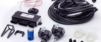
Before you begin installing fog lights, you will need to select a certain list of tools and additional elements. You can purchase a ready-made connection kit or select the necessary spare parts separately. When everything is prepared, you can mark on the front bumper a place for installing future headlights. The VAZ 2115 comes with standard holes from the factory, but in the case of the VAZ 2113 and VAZ 2114 you will need to work with a tool (a jigsaw or a drill). If you don’t want to damage the bumper, you can install the lighting fixtures on special brackets.
To install foglights in the front bumper, you need to make holes using a jigsaw or drill with drill bits, having previously completed the markings
You will need:
- file;
- drill and drill bits;
- electric jigsaw;
- roulette;
- marker.
Installation materials
As a rule, the kit for installing PTF on VAZ 2113, 2114, 2115 includes the following elements:
- headlights with bulbs;
- set of wires;
- electromagnetic relay;
- PTF power button;
- ties and clips for fixing wires;
- PTF connection diagram VAZ 2113, 2114, 2115.
The kit for connecting fog lights should include wires with terminals and connectors, a relay, a button
The installation of the lighting sources in question must be carried out using a button and an electromagnetic relay. The fact is that fog lights consume quite a lot of current and connecting directly to the ignition switch will lead to burning and subsequently burnout of the contacts. All this can contribute to damage to the wire insulation and the occurrence of a short circuit, which may result in failure of the electrical wiring.
Step-by-step installation and connection of PTF
To install fog lights, the following procedure must be followed:
- Installation of the headlight switch button in the cabin. You can choose any location for the element, as long as the driver can easily operate the key. Quite often, the part is installed instead of plugs on the dashboard.
- The grille with the dynamic head is removed from the front panel. Behind it there are two blocks designed to turn on the headlights, indicate the operation of the PTF and illuminate the button.
- Having placed the button in a convenient place, connectors are connected to it. After this, the grate can be put back in place.
- The relay is installed under the hood on the partition of the engine compartment near the mounting block. To remove it, you need to unscrew 2 nuts, lift it and find 2 pads (numbers 7 and 8).
- A block with a harness of four wires with contacts included in the kit is laid to the relay block.
- The connection of the wires that come from the PTF relay is carried out according to the diagram in the following order: the wire from the 30th contact of the relay is connected to block No. 8 of the mounting block at the 8th terminal, the 87th contact of the relay goes to the 1st terminal of the connector, 86 is “ground”, and 85 is connected with the 17th terminal of block No. 7.
- The positive wires are pulled to the PTF, the mass is mainly secured to the nut of the headlights. The “+” voltage is supplied to the fog lights from the 2nd and 3rd contacts of block No. 8.
- After all connections, the connectors are installed in the mounting block and secured.
As for the rear PTFs on VAZ 2113, 2114, 2115, on these modifications of the car such a light source is installed from the factory, i.e. another light bulb is used in the rear light. Control is also carried out from the passenger compartment using a button, but without fixing, since a slightly different relay design (electronic) is used. It’s worth knowing about this and not trying to install a latching key.
Video: installing PTF on a VAZ 2114
Checking the performance of PTF on VAZ 2113, 2114, 2115
After the lighting devices are installed and connected, you need to check how correctly everything works. To do this, just turn on the headlights and press the key that supplies voltage to the PTF relay, after which the headlamp lamps should light up. When the headlights are turned off, the PTF lamps should also go out, regardless of the position of the fog light button. After checking the functionality of the light source, you will need to adjust the light output so that oncoming drivers are not dazzled.
After installation and connection, we check the operation of the PTF: when the lights are turned on and the fog lights are pressed, the lights should light up, when the lights are turned off, the lights should go out
Fog optics are essential lighting equipment for any car. Such devices greatly facilitate travel in poor visibility conditions. If a certain car model does not have PTF installed from the factory, you can carry out the installation yourself. This does not require special tools or special skills and knowledge.
Car diagram - Lada Samara 2
This article provides electrical circuit diagrams of equipment for the VAZ 2115 1997+. The interior of the VAZ-2115 has become more comfortable, a new, more convenient and advanced instrument panel has appeared, which has a more streamlined and ergonomic shape, backlit push-button switches and indicator lamps (the so-called “European panel”), an adjustable steering column, a steering wheel from the “tenth” "family, "console" between the front seats. The new heater design provides efficient heating of the interior. The standard equipment includes an on-board driver warning system for closing the door locks, unfastened seat belts, leaving the ignition key in the lock, the level of oil and coolant in the engine, and extreme wear of the brake pads. The luggage compartment has become more spacious and convenient due to the increase in the trunk lid. The power units are similar to the VAZ-21099.
Electrical connection diagram of the wiring harness of the non-contact ignition system
1 – spark plugs; 2 – ignition distributor sensor; 3 – ignition coil; 4 – switch; 5 – carburetor solenoid valve control unit; 6 – carburetor solenoid valve; 7 – carburetor limit switch; 8 – ignition switch; 9 – mounting block; 10 – speed sensor; 11 – electric motor of the engine cooling system fan; 12 – fan motor activation sensor; A — blocks for connection to the front wiring harness; B - scheme of conditional numbering of plugs in the blocks of the ignition sensor-distributor and speed sensor; B - to power supplies; G - to the instrument cluster (signal for tachometer); E - to the instrument cluster (signal for the speedometer)
Electrical diagram of VAZ-2115-20 equipment
1 – headlights; 2 – fog lights; 3 – air temperature sensor; 4 – electric motor of the engine cooling system fan; 5 – blocks connected to the wiring harness of the ignition system; 6 – engine compartment lamp switch; 7 – block for connection to a single-wire type audio signal; 8 – sound signal; 9 – washer fluid level sensor; 10 – front brake pad wear sensors; 11 – oil level sensor; 12 – generator; 13 – engine compartment lamp; 14 – coolant temperature indicator sensor; 15 – starter; 16 – battery; 17 – relay for turning on fog lights; 18 – coolant level sensor; 19 – brake fluid level sensor; 20 – reverse light switch; 21 – windshield wiper gearmotor; 22 – oil pressure warning lamp sensor; 23 – block for connecting to the rear window washer electric motor; 24 – windshield washer electric motor; 25 – instrument cluster; 26 – mounting block. Conventional numbering of plugs in blocks: A - block headlights; B — electric fuel pump block; C — blocks of the mounting block, ignition switch, windshield wiper gearmotor; D — interior lamp
Connection diagram for starter 29.3708 on VAZ-2115
1 – starter; 2 – battery; 3 – generator; 4 – mounting block; 5 – ignition switch; P1 – pull-in winding of the traction relay; P2 – holding winding of the traction relay
Wiring diagram for turning on the rear window wiper and washer
1 – mounting block; 2 – ignition switch; 3 – ignition switch unloading relay; 4 – rear window wiper electric motor; 5 – rear window washer electric motor; 6 – rear window cleaner and washer switch; A - to power supplies
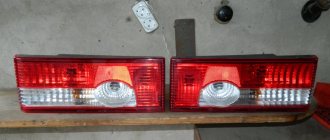
Diagram of the rear lights of VAZ-2115 and 2114 cars in comparison
1 – direction indicator lamps; 2 – side light lamps; 3 – brake light lamps; 4 – fog lamps; 5 – reversing lamps
Connection diagram of the mounting block on the VAZ 2115
The outer number in the designation of the wire tip is the number of the block, and the inner number is the conventional number of the plug: K1 – relay for turning on the headlight cleaners; K2 – relay-interrupter for direction indicators and hazard warning lights; K3 – windshield wiper relay; K4 – lamp health monitoring relay; K5 – power window relay; K6 – relay for turning on sound signals; K7 – relay for turning on the heated rear window; K8 – headlight high beam relay; K9 – relay for low beam headlights; F1-F20 – fuses
Electrical diagram of the ignition switch connections (with the key inserted)
Generator connection diagram
1 – battery; 2 – generator; 3 – mounting block; 4 – battery charge indicator lamp, located in the instrument cluster; 5 – ignition switch
Replacing light bulbs
Now let's replace the rear light bulbs. We lift the trunk and look for a valve in the upholstery located opposite this device.
On the trunk side the lamp is covered with a Velcro flap
We open the valve (it is on Velcro) and observe the back of the flashlight with the power supply connected to it.
Rear part of the lamp VAZ 2114
We pull out the block by pulling it towards the central axis of the machine.
We release the latch located on the side of the lamp that is located closer to the center of the machine, and remove the board along with the lamps.
Removing the board with lamps
We unfold the board with the bulbs facing up and observe the picture shown in the photo in the first section of the article. All lamps are removed in the same way - by turning them counterclockwise. We find the burnt out lamp and replace it with a new one.
Replacing the reverse indicator lamp
The design of the rear lights of the VAZ 2115 - and what kind of light bulbs are in them
The VAZ 2115 has 4 rear lights - two corner ones on the sides (installed in the body) and two more slightly closer to the central axis of the car. The second ones are built into the trunk lid and merge with the side ones, giving the impression of one large lamp.
The central and side rear lights merge, creating the impression of one monolithic light fixture
But this is not the most interesting thing. On the VAZ 2115, the side lights are equipped with 2 double-helix lamps and one single-helix lamp - P21/5W and P21W.
Lamps P21/5W (left) and P21W used in the rear lights of the VAZ 2115
At the same time, this lamp is only responsible for the direction indicators, side lights and brake signal! Why does this lighting device need five spirals? Let's look into this issue.
Diagram of rear lights VAZ 2115
Let's take a look at the electrical diagram of the rear corner light of the VAZ 2115.
VAZ 2115 rear light diagram and coloring of power harness wires
The numbers on the diagram indicate:
- direction indicator, blue (right side), black and blue;
- side light, yellow (starboard), black and yellow;
- brake light, red.
Externally it looks like this:
Rear panel and board of the corner lamp VAZ 2115
It turns out that the double-spiral lamps in each lamp are switched on in parallel - five-watt spirals are responsible for the side light, twenty-one-watt ones are responsible for the brake signal. It is difficult to say why this was done.
This can be done for originality of appearance or for reliability - one lamp burns out (especially on the road you won’t notice it right away) - you can always reach the garage with a second one without creating an emergency situation.
The double “dimensions” look impressive
Look at the small additional taillights located in the trunk lid - they have two P21W lamps (see photo above) each. One is responsible for the rear fog light, the second for the reverse signal. The diagram of these lights looks like this:
Diagram of the internal rear lights of the VAZ 2115 and colors of the power harness wires
In the figure the numbers indicate:
- reverse lamp, green;
- fog lamp, black and red.
Expert opinion
Alexey Bartosh
Specialist in repair and maintenance of electrical equipment and industrial electronics.
The VAZ 2115 has another rear light - a brake light repeater. It is located on the spoiler and uses LEDs as a light source.
Brake light repeater for VAZ 2115