I have been using the “old lady” VAZ 2105 for many years, and it has never let me down, and always drove home on its own. That's why I try to treat her the same way she treats me. But the years of age of the car take their toll, and in no way can it compete with its younger “rivals”. But the situation when, due to my own forgetfulness, I did not turn off the headlights, and in the morning they found the battery discharged to zero, has happened to me more than once. And one fine day, after unobtrusive communication with a traffic inspector, he suggested a simple solution: install Daytime Running Lights, or DRLs for short, on the car.
No sooner said than done, and the next day I went to the nearest car market. I would like to immediately warn you against buying universal DRLs (not for a specific model) via the Internet or by mail: you still need to try them on whether you like it or not, and not all sellers will give accurate information on the size. That’s why I settled on simple DRLs from the “Chinese brothers” for only $11. In the box
in addition to the very thin diode lights themselves, two in number, there were two simple brackets, and eight screws: four larger ones for securing the brackets themselves to the body or bumper of the car, and four smaller ones for attaching the lights directly to the brackets. However, further practice has shown that we will not need either brackets or these “dead” screws. At first I tried to put it in the niches, but I couldn’t, then I could put the main headlights in place, and I just didn’t like it on top myself. Fortunately, it got dark quite early (or I was fiddling with them for so long), and deciding that “the morning is wiser than the evening,” I went home. And the popular proverb turned out to be right and I dreamed about how to install daytime running lights on my VAZ 2105. For reference: this entire article can be successfully applied to the VAZ 2107, in terms of headlights and the wiring we need, they are absolutely identical.
For installation you will need a screwdriver that will perform the functions of an autonomous drill,
extension cord and two Phillips bits for it, 3 and 4 mm drills, Phillips screwdriver; four shorter screws to secure the back of the DRL to the main headlight itself, and four thin and long ones to attach the light bulb with glass to the body. In addition, you need a mounting block, or rather only two segments from it, electrical tape (where would we be without it), transparent silicone sealant, a meter-long (or even less) piece of two-core wire, plastic clamps to lay everything out neatly, and wire cutters to later bite off the excess ponytails. That's it, let's start creating. We remove both headlights and use a four-inch drill to drill a hole through the bottom. Now comes the neatest part, since the outer glass of these DRLs is not glass at all, but rather brittle and scratchy transparent plastic. Therefore, with a drill, first three, at the lowest speed of the drill, we drill out a through hole. And then using a four-piece drill, we also carefully and carefully increase it to this diameter. In the rear part, on the contrary, there are already holes for thin screws, so we don’t do anything with it. We thread the wire into the prepared hole and put the headlight in place. We screw the back cover of the DRL directly to the headlight, lubricate it along the contour with transparent silicone, and after lubricating the screws themselves with the same silicone, use a SCREWDRIVER and carefully (remember the fragility) screw on first one and then the other headlight.
Daytime running lights have nothing to do with dimensions and are lighting devices that improve the driver's visibility during the daytime.
The standard DRLs are LEDs, which shine brightly and have a long service life. When you use daytime running lights on a VAZ 2107, you should not additionally turn on the low beam or fog lights.
Daytime running lights for VAZ 2107
Switching on through dimensions or low beam
The second version of the DRL connection diagram involves using the power circuit of the side light bulb.
To do this, the positive wire from the running lights is directly connected to the “+” from the battery. In turn, the negative wire is connected to the “+” of the side light, which is currently electrically neutral. As a result, the following current flow path is formed: from the “+” of the battery through the LEDs to the size, and then through the light bulb to the body, which serves as the minus of the entire circuit. Due to the low current consumption (tens of mA), the LEDs begin to glow, and the lamp spiral remains extinguished. If the driver turns on the side lights, then +12 V appears on the positive side of the side lights, the potentials on the DRL wires are equalized and the LEDs go out. The circuit goes into normal mode, that is, current flows through the side light bulbs.
This circuit solution has several disadvantages:
- running lights remain on when the engine is turned off, which is contrary to current regulations;
- the circuit will not work if LEDs are also installed in the dimensions;
- the circuit will not work correctly if the DRLs contain powerful SMD LEDs, the rated current of which is comparable to the current of a light bulb;
- For safety reasons, an additional fuse must be installed.
This connection method can be improved by connecting the positive wire of the LED module not to the “+” of the battery, but to the “+” of the ignition switch, thereby eliminating the first drawback.
Some motorists use schemes for turning on running lights through a low beam lamp. That is, when the low beam is turned on, the DRLs automatically go out, but in other cases they work. In addition to the above disadvantages, this method does not comply with GOST R 41.48-2004 and traffic rules.
When parking a car at night, side lights are used to indicate it; the use of DRLs is prohibited.
How to make daytime running lights with your own hands
To make your own DRLs, you usually use cheap fog lights, LED strip, aluminum plates, silicone sealant and a soldering iron. The assembly sequence will be approximately as follows:
- First, the old fog lamp is disassembled and the internal filling is removed.
- Next, an aluminum plate is cut to the size of the flashlight body.
- A piece (or 2 pieces) of LED strip is cut to the size of the plate.
- An adhesive-sealant is applied to the degreased aluminum surface, and the LEDs are attached.
- All that remains is to use a soldering iron to connect the pieces of luminous tape and the electrical wire in series.
- The headlight is already assembled with a new filling.
To connect such DRLs, select one of the circuits suitable for a given car (it is better to connect via a DRL controller or via a relay and oil pressure sensor, as in the video below).
Installing daytime running lights on a car with your own hands becomes not only an interesting pastime. The result of the work will be a reason for pride for the car owner, because he managed to create a new image for his iron horse on his own.
Lada 2107 Green-Devil › Logbook › Installing DRLs on the “seven”
As you know, in 2022, on January 1, we will be required to have daytime running lights (DRLs). That's why it's worth installing them today. We connect them in series with the ignition key, so that when you turn the key, the daytime lights come on immediately. There is also the option of introducing DRLs through a five-pin relay, which will be connected to the oil pressure light, then at start the “running lights” will turn on themselves. But there will be an additional load on the generator, and this is not very profitable.
Daytime lights can be bought, but the price is 600-800 rubles. Their installation and installation is much simpler than homemade ones. However, such DRLs are disposable and have certain limitations on current strength, so it is better and cheaper to assemble everything yourself. Then you can replace something if it breaks, and adjust the intensity of the light from the “running lights”, and here we have it regulated!
You can etch the DRL board yourself. To do this, take the workpiece, clean it, degrease it. Next, we apply a protective coating and remove excess residue (etch). We drill holes for contacts and fasteners. The last stage is to roll everything up with flux and puddle it. That’s it, we have the preparation, let’s make a couple for it. We solder 30 LEDs per board, connecting every 3 LEDs with a 500 Ohm resistor. After installing the LEDs on the boards, we ennoble our circuits into plastic cases, treating everything with sealants. Some experts recommend drilling holes directly in the DRL housing for ventilation, so that there is no greenhouse effect when there is a temperature difference, and your electronics do not become damp or short-circuited. We assembled ready-made DRLs, tested them via power supply, if everything works, then we go to install them in the bumper.
We drill holes and fix the DRLs according to the regulations (the edges of the lighting should be at a distance of 600 mm, this distance can be reduced to 400 mm if the width of the car is less than 1300 mm). The horizontal angle is 20 degrees outward and inward, and the vertical angle is 10 degrees up and down from the horizontal. In general, daytime running lights are not designed to illuminate the road, but to identify your car to other vehicles. This means they are aimed directly at the eyes of the oncoming driver, while having a brightness of at least 400 cd in order to be noticed. And no more than 800 cd, so as not to blind the driver of an oncoming vehicle.
READ Lg 42ld555 how to connect to the Internet
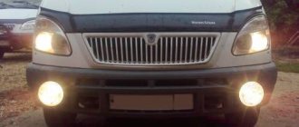
Unfortunately, due to different design features, when installing DRLs on a VAZ 2107, some traffic cops confuse them with “fog lights,” and it’s no wonder, since they are located very close. There is an option to put it under the bumper. If this does not go against GOST, curbs and snowdrifts can easily damage or even break the protective frame and even the LEDs themselves. “Fog lights” with built-in LEDs are also sold, however, this also has its disadvantages: the location of the DRLs under the “fog lights” can be much lower than normal, and the headlight itself is not designed for LEDs and simply does not provide the necessary illumination.
According to the regulations, daytime running lights must be turned on with the main headlights, but there are exceptions when they are used for a short period of time, for example to indicate an alarm. For the “seven” it is still possible to make a separate switch for the DRL, but not all traffic controllers will treat this with understanding.
By and large, DRLs are not listed anywhere in the design of the VAZ 2107, which means that when installing such a device, it must be certified. So far, the regulations do not say anything about this, but perhaps in the future they will introduce an “obligation” for the certification of DRLs. Especially if they are homemade. After all, we all know how our government loves to enrich itself by forcing ordinary car enthusiasts to buy expensive “stampings”, which, although they have a certificate, break down with surprising frequency.
Source
Installation rules
Installation of additional lighting on a domestic car does not require qualifications or experience. However, if installed incorrectly, you risk running into a fine from traffic cops, becoming the owner of an administrative violation.
To prevent this from happening, connect following the rules:
- read GOST R 41.48-2004. It concerns the rules for installing lighting devices on a car and vehicle certification in this regard. All the parameters that you must consider when installing these devices are written there;
- select the appropriate DRL body shape. Keep in mind that not all lighting devices are suitable for the VAZ 2107. Drivers consider it the best choice in terms of price-quality ratio;
Philips LED DayLight 9 daytime running lights
- Check the housing size for correctness, taking into account the blocks of adjacent Daytime Running Lights. Install lighting fixtures in the air intake or on the bumper, depending on the situation;
- The height of the framed product body is 250-1500 mm from the road surface. The width between the inner edges of 2 surfaces visible on the car must be at least 600 mm;
- the products are located in front of the machine, and the beam of rays is directed forward;
- Consider the overall brightness of the LED lighting. It is 150-330 lumens.
Scheme options
So, you can connect in several ways.
- The DRL turns on as soon as the ignition key is turned. The lights do not go out until the car engine stops. It is considered the simplest method, which does not involve the use of an on-board network. It is enough just to connect the negative from the lights to any place in the car body, and connect the positive from the lock to the output of the high-voltage module, always through a fuse.
- The same scheme, only the DRLs go out immediately as soon as the low beam is turned on. To implement this connection option, you need to adhere to the diagram described above, with the only difference being that the negative is connected to one of the positive wires of the low beam lamp. As soon as the low beam on the car is turned on, a positive impulse will appear on the minus DRL and the lights will go out. The DRLs will light up again as soon as the high beams are activated or the headlights are turned off.
- Connection diagram, which involves automatic connection of the DRL as soon as the car engine starts. It is considered the most reliable option for self-integrating LED daytime running lights. To implement this scheme, the minus of the DRL is connected to the car body, and the plus is connected to the relay contact.
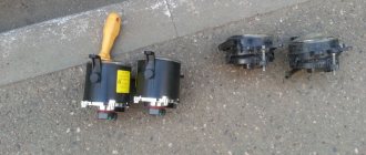
Simple circuit with 4-pin relay
There is a simplicity in circuit number 1, implemented through a 4-pin relay. However, this option does not always satisfy the requirements of GOST, since the DRLs will shine separately from the head optics. The lights are not turned off by a push-button mechanism, everything happens automatically.
The photo above shows exactly this circuit, connected via a 4-pin relay. It implies the following procedure:
- when the engine starts, an impulse is sent from the generator to the relay, and the LEDs light up;
- As soon as the headlights are turned on, the DRLs turn off.
This connection method is also possible without using a generator. Then, instead, the voltage source will be the battery, the positive of which should be connected to the 30th contact in the photo.
It is also possible to connect the plus from the parking brake. In this case, as soon as the handbrake is activated, the daytime lights will go out - that's the button.
Circuit with 5-pin relay
It involves the use of 4 contacts. Ideal connection option for Priora cars. The difference from the above diagram is not only in the number of relay contacts. This circuit does not provide for the use of output 87. An alternative to ground is output 86.
The circuit with a 5-pin relay provides for the use of DRL control. The push-button mechanism is built between the generator and the 30th relay contact.
The operation of the DRL is as follows:
- the internal combustion engine is started, thereby the impulse from the generator goes to the 30th contact of the relay, and from there to the plus of the DRL;
- the lights come on, the minus is connected to any part of the car body;
- when the dimensions are used, the coil is activated, the 30th contact is integrated with the 87th, the pulse no longer arrives - the DRL is turned off.
With reed switch
The photo above shows a detailed connection diagram for the option using a generator. The plus is integrated, as can be seen from the diagram with point 30. The relay contact, marked with point 87, is integrated with the battery positive. Another relay contact, marked with number 85, is connected to the vehicle ground through the DRL.
The contact marked on the diagram with point 86 is connected to the reed switch. From the reed switch there is a connection to the plus of the generator.
Thus, the scheme implies the following. As soon as the internal combustion engine starts, the driver activates the reed switch with a button, the relay is activated, and the DRL turns on. The reed switch must be packed in thermopolymer and securely fixed to the generator.
Without reed switch
A variation of circuit number 3, only without using a reed switch. In this case, the contact marked 86 is integrated with the oil pressure lamp in the instrument panel. Thus, the option of turning on the DRL after the engine is started is supported.
It is noteworthy that this scheme is much easier to implement with your own hands than the option with a reed switch.
Video: how to connect DRL from a generator
As you can see, connecting the DRL to the vehicle’s on-board network is carried out using several circuits. The plus is taken from the output of the generator, less often from the battery.
- Absolutely legal (Article 12.2);
- Hides from photo and video recording;
- Suitable for all cars;
- Works through the cigarette lighter connector;
- Does not cause interference to radios and cell phones.
SPA-05 + DRL. Part 2 (Wiring) Read for everyone!
In fact, this article will be devoted indirectly to wiring for DRLs.
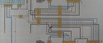
I would even say that it is rather devoted to wiring 2107 (04.05) in general, using the example of connecting DRLs. Our illiteracy very often makes us think about what and how we do everything related to electricity in cars. I mean, first people write posts asking for help connecting them to some kind of device to the on-board network. Then a lot of “Smart” (smart in quotes) advice pours in: take the “+” from the ignition switch, take the “+” from the cigarette lighter, pull from the battery and so on. Yes, that’s what a person does: he removes the steering wheel cover, climbs to the lock, looks for holes from the engine compartment to the interior, or drills them if he has something, in general, whoever knows what. Then for about half a year it all works until the hairs that were pulled rub against the sharp edges of these drill holes, fly off from the ignition switch and short out something somewhere. And now posts of a different nature - fuses constantly blown, something stopped working, or the car even burned down while I ran to the store for cigarettes (God forbid to anyone). But all this can be avoided, and without looking for adventure, you just need to devote about half an hour to a scheme that everyone has seen but everyone is too lazy.
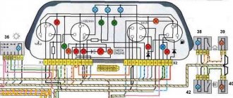
This scheme dates back to 1988. but it is also relevant for cars of early production, since in 1988 they did not add anything but only removed what was superfluous, according to AvtoVAZ.
What is all this for? Everything is simple if you look at the diagram, and whoever climbed into the wiring and removed the fuse box should have noticed that there are 8 contacts in the wiring chips (in chip 13 there are 6 - an additional braid to the rear of the car, in chip 14 there is one blue wire). But the wiring is not connected to everyone. Nevertheless, there are contacts on the fuse block and, moreover, they are routed in the fuse block, and this is exactly what I want to talk about. (Whether you rate it or not is all the same, I’m writing for myself personally because over time everything is forgotten and it’s easier to look at it than to look for it again).
And so personally, I perceive information better with my eyes (in the sense of diagrams and pictures as opposed to text). So I'll draw a little