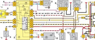
The dimensions of the Gazelle are almost the same for all models. All the differences come down mainly to the switches. On the first models of Gazelles type 3302, switching is carried out by the central light switch. Subsequent models were equipped with lighting control units. The operating principle of these modules boils down to the closure of certain contacts when the control handle is turned. The connection diagram for Gazelle 3321 is somewhat different. They use an intermediate relay to unload the switch contacts. This would not hurt to do business with Gazelles, but the designers considered it unnecessary.
Gazelle dimensions diagram check.
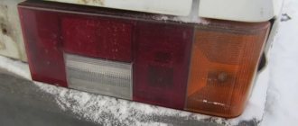
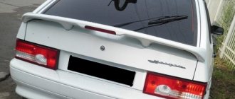
Rear lights do not light up
What to do if the Gazelle’s dimensions do not light up completely, or some individual lamps? Most often, the rear lights on gazelles do not light up. If this happens, then first you need to check the simplest thing, the presence of power in the sockets and the serviceability of the lamps. If there is no plus, you need to check the condition of the contacts in the connector; for on-board gazelles this is the most problematic place.
The fact is that the size wire has constant power while driving, since according to traffic rules, all cars drive with their headlights on. Despite the protective rubber bands, water gets into the connector and, under the influence of electrolysis, the metal of the contacts is destroyed very quickly. This can be determined by the green coating in the connector. On minibuses, the connection is made in the cabin and they are practically indestructible.
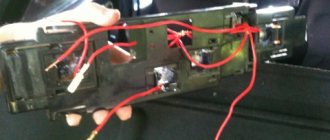
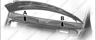
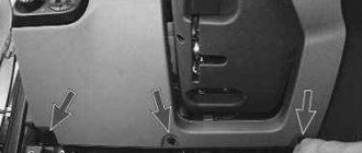
But there is one more problem area that is characteristic of absolutely all Gazelles. The fact is that the rear part of the wiring has a connection of wires in the area of branching into the right and left sides. This place is also highly susceptible to electrolysis destruction, since water, getting under the insulation, remains there and constantly affects the wires. But before you go there, check that there is power in the front harness connector and the rear harness connector. These connectors are located in the engine compartment in the area of the vacuum brake booster and are also exposed to liquids.
Basic recommendations for replacing lamps
In order for the light to be of high quality, you need not only to carry out the work correctly, but also to use high-quality products, let's start with this.
How to choose a quality option
To avoid making mistakes when purchasing, remember a few simple but useful recommendations:
- It is important that the product meets the required parameters. The model we are considering uses lamps with an H7 base; the power required is 55 Watt, voltage 12 Volts.
Hella products have earned a good reputation among car enthusiasts
- It is very important to choose a high-quality option, so low price should in no case be the determining factor; most often, cheap products do not last long and do not work at all as stated. Give preference to well-known brands that have been on the market for a long time.
- You should not purchase products that do not meet factory requirements. For example, the use of xenon is contrary to traffic regulations, or if you purchase halogen lamps of too high power, the quality of light is unlikely to improve, but the load on the wiring will increase, which can lead to accelerated wear. (See also the article Gazelle wiring diagram: features.)
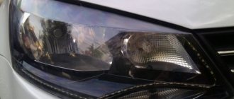
The low beam is always located closer to the bumper, the high beam is closer to the radiator
Replacement features
Let us note right away that the process can be complicated by the fact that you will need to stick your hand into the lampshade; if you want to see what is located inside and how, then take a small mirror.
Instructions for doing the work yourself are as follows:
- First of all, remove the plug, which covers the connection point of the light bulb and serves as protection against moisture and dust getting inside. Simply pull one of the edges and carefully remove the cover from its seat.
If the cover is damaged, it is better to find a new one, as moisture and dirt will penetrate into the housing
- Next, you need to disconnect the block of wires, this should be done very carefully, in no case do not pull on the wires themselves, grab the connection body and pull it out, sometimes it happens that this element is difficult to remove, in this case do not pull very hard, it is better to loosen it first him, and then he will get it much easier.
- The lamp base holds a special clamp that securely fixes and presses the entire assembly. To release it, you need to press on the rounded side and disengage it from the hook, after which the second side will release itself. This is not very clear in words, so look at the photo below, it clearly shows both the clamp itself and the buckwheat on which it is held.
The spring clip must be pressed and then pulled up, after which the system will be released
- You remove the lamp and install a new one in its place; there are special slots on the base, so choosing the correct position will not be difficult. Next, you need to put the clamp in place; to do this, one side is inserted under the hook, and the second is pressed and placed under the other support.
Important! Do not touch the glass part of the lamp under any circumstances, as it heats up during operation, and particles of fat from the skin cause darkening and accelerated failure of the product. If you do touch the flask, wipe it with a cloth soaked in an alcohol solution.
The dimensions on one side do not light up.
When the rear lights on a Gazelle don’t work, we figured it out. If the lights on one side do not light up, then you need to check the fuses and replace the blown ones. If the fuse blows again during installation, there is a short circuit in the circuit. To find it, you need to disconnect the connector of the rear and front harness. This will allow you to determine which harness contains the short circuit. You should do the same in order to eliminate short circuits in headlights and rear lights. The specific location can be determined by examining the corresponding harness.
Advertisements on NN.RU – Auto
With us you can not only extend the frame to fit a body of 5.1 m, 6.2 m, 7.5 m, 9 m for Maz Zubrenok, Maz, Kamaz, Ural, Zil, Mitsubishi, Nissan.
A specialized company for converting trucks into tow trucks invites you to install a tow truck platform on.
Lengthen Kamaz under a body 7.5 m Lengthen Maz Zubrenok, Maz under a body 9 m Re-equipment of the chassis of an extended truck.
Lengthen Gas 331043, 331063 Valdai-farmer for installation of a body 5.1/6.5 m. The chassis is lengthened by increasing the wheel size.
Source
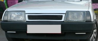
The front lights do not light up.
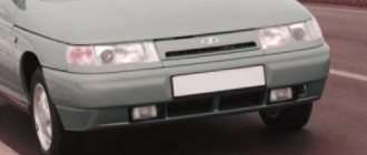
Loss of contact of the front dimensions most often occurs in the connectors of the headlight unit. This mainly happens on Gazelles of the first editions. Loss of contacts is possible not only from the outside, but from the inside of the connector. To eliminate the malfunction, it is enough to unscrew one or two self-tapping screws, depending on the design, carefully remove the socket and clean the contacts from the inside. On Gazelles, restyling and business problems in the headlight unit are extremely rare.
The last option is when the Gazelle’s dimensions are not fully activated. You should start checking the Gazelle circuit with the fuses near the battery. On the first models, this practically does not happen unless the contact on the central switch or connected wires loosens. Most often, such a malfunction appears in restyling Gazelles. This is due to the use of a relay in the headlight circuit, through the contacts of which the current also passes to the headlight lamps. In this case, not only the relay fails, but also the socket where it is inserted, especially when the contacts are loosened. The relay is located on a bracket under the panel, on the steering column.
Please tell me! The dashboard lights do not light up, the indicators are on, but the dashboard backlight itself has stopped lighting up. Also, the instrument panel light switch does not light up. Don't know where the reason is? The fuse is intact.
Fuses and relays GAZelle NEXT, 2013 - present.
The truck's power circuits are protected by relays and fuses. The elements are installed in blocks that are located in the engine compartment and in the passenger compartment.
The models considered are GAZelle Next (A21, A22, 41, 42) 2013, 2014, 2015, 2016, 2022, 2022, 2022 CUMMINS TURBODIESEL ISF2.8S4129Р (120 hp).
In the engine compartment
In the engine compartment, the relay and fuse mounting block is installed on the bulkhead extension on the left side.
| Assignment of fuses in the engine compartment mounting block | ||
| № | Protected circuit | Current, A |
| F1 | PTF relay winding | 15 |
| F2 | Brake lights | 10 |
| F3 | Horn relay coil | 20 |
| F4 | Fuel heater relay coil | 25 |
| F5 | Coolant preheater | 25 |
| F6 | Instrument and starter switch (ignition switch) | 25 |
| F7 | ABS system | 25 |
| F8 | Reserve | — |
| F9 | Middle sows (left headlight) | 10 |
| F10 | Low beam (right headlight) | 10 |
| F11 | High beam (left headlight) | 10 |
| F12 | High beam (right headlight) | 10 |
| F13 | Side light bulbs (left side) | 10 |
| F14 | Side light bulbs (right side) | 10 |
| F15 | Reversing lamps | 10 |
| F16 | Reserve | — |
| F17 | Heater | 15 |
| F18 | ABS system | 25 |
| F19 | Reserve | — |
| Relay | ||
| K1 | starter | |
| K2 | fuel heater | |
| K3 | return the wiper blades to their original position | |
| K4 | dipped headlights | |
| K5 | high beam headlights | |
| K6 | fog lights | |
| K7 | sound signal | |
| K8 | starter blocking | |
Vehicle electrical circuits that consume high current are protected by fuse links . The inserts are installed in a common block (BPR-4.10), fixed in the engine compartment on the right side.
| Block fin inserts (BPR-4.10) | ||
| № | Purpose | Current, A |
| 1 | air heater circuit in the intake pipe | 125 |
| 2 | general “positive” purpose of the car, except for the “positive” generator and starter circuit | 90 |
| 3 | reserve | 40 |
| 4 | engine control unit power supply circuit | 30 |
In the cabin
In the cabin, the relay and fuse mounting block is installed under the lower decorative panel in the instrument panel.
| Assignment of fuses in the interior mounting block Next | ||
| № | Protected circuit | Current, A |
| F1 | Windshield wiper, windshield washer | 20 |
| F2 | Lighting control module, instrument lighting | 10 |
| F3 | Electric mirrors | 5 |
| F4 | Electric windows | 25 |
| F5 | Heated exterior mirrors | 10 |
| F6 | Heated driver's seat | 10 |
| F7 | Additional heater | 15 |
| F8 | Reserve | — |
| F9 | Lockable differential | 10 |
| F10 | Second row seat socket | 15 |
| F11 | Reserve | — |
| F12 | — | |
| F13 | Daytime running lamps | 7.5 |
| F14 | Rear fog lamps | 5 |
| F15 | Direction indicators | 10 |
| F16 | Instrument cluster, speed sensor, heater remote control | 7.5 |
| F17 | Engine management system | 5 |
| F18 | ABS system | 5 |
| F19 | Cigarette lighter fuse next, socket | 20 |
| F20 | Hazard warning lights | 15 |
| F21 | Lighting control module, backlight | 15 |
| F22 | Interior lighting | 10 |
| F23 | Central locking, audio system head unit | 15 |
| F24 | Instrument cluster, diagnostic connector, pre-heater control panel | 5 |
| Relay | ||
| K1 | Wiper | |
| K2 | Heater | |
| K3 | Power target of the instrument switch and starter (ignition switch) | |
| K4 | Coolant preheater | |
Gazelle dimensions diagram check.
Rear lights do not light up
What to do if the Gazelle’s dimensions do not light up completely, or some individual lamps? Most often, the rear lights on gazelles do not light up. If this happens, then first you need to check the simplest thing, the presence of power in the sockets and the serviceability of the lamps. If there is no plus, you need to check the condition of the contacts in the connector; for on-board gazelles this is the most problematic place.
The fact is that the size wire has constant power while driving, since according to traffic rules, all cars drive with their headlights on. Despite the protective rubber bands, water gets into the connector and, under the influence of electrolysis, the metal of the contacts is destroyed very quickly. This can be determined by the green coating in the connector. On minibuses, the connection is made in the cabin and they are practically indestructible.
But there is one more problem area that is characteristic of absolutely all Gazelles. The fact is that the rear part of the wiring has a connection of wires in the area of branching into the right and left sides. This place is also highly susceptible to electrolysis destruction, since water, getting under the insulation, remains there and constantly affects the wires. But before you go there, check that there is power in the front harness connector and the rear harness connector. These connectors are located in the engine compartment in the area of the vacuum brake booster and are also exposed to liquids.
The dimensions on one side do not light up.
When the rear lights on a Gazelle don’t work, we figured it out. If the lights on one side do not light up, then you need to check the fuses and replace the blown ones. If the fuse blows again during installation, there is a short circuit in the circuit. To find it, you need to disconnect the connector of the rear and front harness. This will allow you to determine which harness contains the short circuit. You should do the same in order to eliminate short circuits in headlights and rear lights. The specific location can be determined by examining the corresponding harness.
Replacing the old instrument cluster with a new one
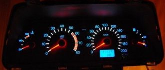
Many car owners of a gazelle or Volga car with an old-style instrument panel strive to change it to a new-style instrument panel, in which most of the indicators have been replaced with modern LED ones, and such an instrument panel looks much prettier and brighter.
So, to remove the instrument cluster, first remove the trim by unscrewing the four screws. Then remove the four screws securing the combination; disconnect the electrical connectors and remove the instrument cluster. Repair the instrument cluster by block replacement of faulty devices. To replace devices, remove the protective glass and unscrew the nuts securing the faulty device on the reverse side.
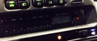
The reason why many drivers install the Gazelle Business dashboard is because it looks better. The second reason why you should buy this particular panel option is the functionality and increased number of opportunities to monitor the performance of the car.
The euro-type panel has 2 large dials - speedometer and tachometer, as well as 2 small ones, which display the amount of gasoline and the temperature of the coolant. The rest of the information about the state of the nodes and any errors that have occurred is displayed using illuminated indicators in the middle of the panel. A simpler design significantly relieves the driver’s attention.