Checking the field winding for interturn short circuit
The interturn short circuit causes an increase in the excitation current. Due to overheating of the winding, the insulation is destroyed and even more turns are shorted together. An increase in excitation current may lead to failure of the voltage regulator. This malfunction is determined by comparing the measured field winding resistance with the specifications. If the winding resistance has decreased, then it is rewound or replaced.
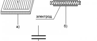
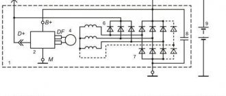
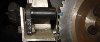
The interturn short circuit in the excitation winding coil is determined by measuring the resistance of the excitation coil using an ohmmeter available at stands E211, 532-2M, 532-M, etc., a separate portable ohmmeter (see Fig. 14, c), or according to the readings of an ammeter and voltmeter when the winding is powered from a battery (see Fig. 14, d). The fuse protects the ammeter and battery in the event of an accidental short circuit. Probes are connected to the rotor slip rings and by dividing the measured voltage by the current, the resistance is determined and compared with the technical specifications (see Table 2).
Rice. 14. Checking the field winding:
a—on a cliff; b—for short circuit with the shaft and pole; c - with an ohmmeter for open circuit and interturn short circuit; g — — connection of instruments for determining resistance.
Checking the stator winding for a break. Checking the stator winding for a break is carried out using a test lamp or an ohmmeter. The lamp and power source are alternately connected to the ends of the two phases according to the diagram in Fig. 15, a. If there is a break in one of the coils, the lamp will not light. An ohmmeter connected to this phase will show “infinity.” When connected to the other two phases, it will show the resistance of those two phases.
Interturn short circuit in the generator winding. How to detect. Advice from an auto electrician.
If the channel brings you real benefits, then support the project! The amount doesn't matter! CARD (SBERBANK)…
Interturn short circuit in the stator winding of the generator.
If the channel brings you real benefits, then support the project! The amount doesn't matter! CARD (SBERBANK)…
Checking the stator winding for a short circuit with the core. If such a malfunction occurs, the power of the generator is significantly reduced or the generator does not work, and its heating increases. The battery is not charging. The test is carried out with a 220 V test lamp. The lamp is connected to the core and any winding terminal according to the diagram in Fig. 15, b. If there is a short circuit, the lamp will light up.
Checking the stator winding for interturn short circuit. Interturn short circuit in the stator winding coils is determined by measuring the resistance of the phase coils with a separate ohmmeter (see Fig. 15, c), on stands E211, 532-2M, 532-M and others, or according to the diagram shown on rice. 15, g. If the resistance of two windings (measured or calculated) is less than that indicated in the table. 2, then the stator winding has an interturn short circuit. This fault can be detected using the stator winding zero point. To do this, it is necessary to measure or calculate the resistance of each phase separately and, comparing the resistance
Rice. 15. Checking the stator winding:
a - on a cliff; b - for short circuit with the core; c - for interturn short circuit and open circuit
ohmmeter; d - connection of instruments to determine the resistance of the stator winding
all three phases, determine which of them has an interturn short circuit. A phase winding that has an interturn short circuit will have less resistance than others. The defective winding is replaced.
The serviceability of the stator windings can be checked on test benches for phase symmetry. During this test, the alternating voltage is measured between the phases of the stator winding up to the rectifier unit at the same (constant) generator rotor speed. If the voltage induced (induced) in the stator windings is not the same, then this indicates a malfunction of the stator winding.
What components and parts are checked using a multimeter?
This operation involves diagnosing the electrical part, and checking the following parts:
- Voltage measurements are taken at the generator output;
- the rotor excitation winding is checked for open circuit or short circuit to the housing;
- checking the stator windings for breakdown and open circuit;
- carry out fault detection of the diode bridge, capacitor;
- faults in the voltage regulator and brushes are detected;
Performing each of the listed operations requires special knowledge and skill to carry out measurements, so each test should be considered in more detail.
Checking generator components
The test begins with monitoring the functionality of the voltage regulator. To do this, the regulator is removed from the generator and a simple electrical circuit is created.
Any car interior light bulb can be used as an incandescent lamp. If voltage regulator 3 is working properly, lamp 6 should not glow at full power. When connected in parallel with the lamp (brushes) of a multimeter, its readings should be from 5.0 to 10.0 Volts. If the multimeter readings fall outside these limits, the regulator must be changed. The design of some generator models allows for the possibility of replacing the regulator without dismantling the device.
Output voltage level measurement
For each individual unit this value will be different. Let's take a closer look at checking a car generator. Set the voltage measurement mode on the multimeter scale. First you need to check the voltage with the engine turned off. To do this, measure the voltage value at the battery terminals. We connect the red probe to the positive terminal, and attach the black one to the minus terminal. A charged, serviceable battery will produce a value of up to 12.8 V. We start the engine. Then we take a measurement. Now this value should be no more than 14.8 V, but no less than 13.5 V. If the voltage level is higher or lower, the generator is faulty.
Common breakdowns
Generator faults can be electrical or mechanical. These include:
- loss of functionality of the voltage regulator;
- breakdown of the rectifier unit (diode bridge);
- short circuit of stator windings;
- current short circuit in the rotor winding;
- wear of bearings and brushes.
Read also: Why does the reducer on a gas cylinder hum?
Voltage regulator
The purpose of this unit is to normalize the voltage before feeding it into the automotive electrical circuit. You can check the serviceability of the regulator by checking the voltage that it supplies to the battery terminals. This indicator depends on the model and brand of the vehicle and varies between 13.5-15.5 V. Therefore, you should find out in advance what voltage your particular type of regulator produces. This can be done by studying the manual for using the machine. For example, you can take a VAZ 2107 or 2110 car, since these vehicles have the most typical faults associated with the integral and relays.
Using a Multimeter
To check the VAZ 2110 generator with a multimeter, you need to switch the device to voltmeter mode. Then you need to connect its probes to the battery terminals. The most important thing is to observe the polarity and turn off the car engine. The voltage normally varies from 12 to 12.8 V. Next, the procedure should be repeated, but with the engine running. The voltage readings should rise to 13.5-15.5 V. Lower and higher voltage values indicate a malfunction of the generator.
Checking the generator without removing it from the car
A bridge of diodes performs the functions of a kind of alternating current converter. It contains three negative and three positive diodes.
Before checking the bridge, you need to disconnect all the wires coming from it and from the voltage regulator. You also need to remove the ground anchor from the battery in advance. First you need to check the rectifier for short circuits. We activate the ohmmeter mode on the multimeter and connect the red (positive) probe to the positive contact of the diode bridge, and the negative probe to the surface of the housing of the generator itself. If the rectifier is fully operational, then the readings of the measuring device will go to infinity. In other cases, the rectifier will be inoperative.
Testing of stator and rotor windings
A common breakdown of a car generator is a short circuit in the windings. It occurs when current surges are too intense, brushes wear out and liquid gets in.
So, you need to remove the rotor and find a pair of slip rings on its structure that will need to be ringed. Having started the ohmmeter mode on the multimeter, we connect the probes to these rings. Normal resistance is 2-6 ohms. If you get large values, then there is a loss of contact between the slip rings. If the device shows lower values, then an interturn short circuit has occurred.
The starter has several windings at once. They need to be checked separately. However, first you need to disconnect the wires that connect the diode bridge and the winding terminals.
Then you should measure the resistance between zero and the terminals of the windings. The normal value is no less than 0.3 Ohm.
Wear of brushes and bearings
If you have already disassembled the generator, then it is advisable to check the condition of the brushes. They can wear out or break due to misalignment of the rotor shaft. If the brushes are damaged, they should be replaced with new ones.
Inside a car alternator there are a pair of bearings. One is fixed on the rotor shaft, the other is in the center of the cover. The whistling and hum of the generator when the engine is running is a clear sign of bearing wear. In this case, the generator housing can become very hot. If you notice such signs, it is better to replace the bearings immediately, otherwise you may encounter more serious problems.
You can check the bearing by removing the belt from the generator and trying to rotate its shaft with your own hand. If the part rotates freely and easily, then everything is in order. If it is difficult to rotate the rotor, then you should not delay replacing the bearings.
How to check the generator for performance? Self-check and repair of the generator
A generator is a typical electrical station that provides energy to all engine systems: power, cooling, ignition, so its failure will inevitably lead to other malfunctions. To prevent breakdowns, you need to systematically diagnose it, and if problems cannot be avoided, repair it immediately.
In this article we will talk about how to check the generator for performance without resorting to the help of professionals. But before that, let's look at the symptoms of its possible defects.
Checking the rotor winding
To perform this operation, it is necessary to dismantle and disassemble the unit. When performing a self-test, do not forget to set the device to the circuit resistance measurement mode. Additionally, a value of no higher than 200 Ohm is set. These routine maintenance works are carried out in 2 stages:
- Measuring the resistance value of the rotor windings. To do this, we attach the probes to the rings of the moving part of the engine and determine the value. This will make it possible to determine the probability of a winding circuit break at a value above 5 ohms. If the device shows less than 1.9 ohms, a turn short circuit has occurred. Most often, the chain breaks at the junction of the rotor winding lead to the ring. You can determine the defect by moving the wire with a probe at the soldering points, as well as by detecting darkened and crumbling wire insulation. In the event of a break or short circuit (short circuit), the wires become very hot, so the breakdown can be detected by visual inspection.
- A circuit test is performed to detect a short circuit to the frame. We position the generator rotor conveniently for operation. Then we bring one probe to the rotor shaft, and attach the second to any ring. If the winding is working properly, the resistance reading will go off scale. If it shows low resistance, this part should be sent for rewinding. When rewinding the rotor, it is important to maintain perfect balancing.
Checking the VAZ 2110 generator with a multimeter
It is impossible to imagine a VAZ 2110 car without electrical appliances. Lighting, battery charging, on-board controllers, and electric motors consume electricity generated by the generator. Monitoring the condition of electrical equipment increases the service life of devices and wiring. The article contains practical advice on various ways to check a VAZ 2110 generator with a multimeter.
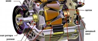
VAZ cars are equipped with three-phase synchronous alternating current generator devices equipped with a diode rectifier and an electronic voltage relay regulator. The V-belt transmits torque from the engine pulley to the electric machine pulley. A constant excitation voltage is supplied to the slip rings with graphite brushes and is removed from the B+ terminal.
Main components of the device:
- front and rear covers with bearings;
- stator;
- rotor;
- diode rectifier bridge;
- output voltage regulator relay;
- brush holder.
Possible faults
Complete or partial jamming of bearings. Symptoms – belt break, incomplete charge of the battery (detected by a warning lamp on the instrument panel, a measuring tester, a load fork).
Checked:
- visually with the engine running;
- Turn off the engine, remove the belt, and turn the pulley by hand. Failure to rotate freely and evenly indicates the need for repair.
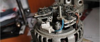
Malfunctions of the stator, rotor. The device is operated in an aggressive environment; dirt and caustic liquids may enter. The insulation of the winding wires is destroyed, causing interturn short circuits to the housing.
Signs – cessation of generation, dim lamp light, indicator light is on, extraneous sounds in the generator. It is checked with the VAZ 2110 generator removed using a multimeter.
The graphite brushes have worn out. Symptoms are the same as in the previous paragraph. Checking and replacement are carried out without removing the equipment. Takes 10 – 15 minutes.
The voltage regulator is not working. Signs:
- Battery charging is insufficient, mains voltage is too low, light bulbs are dim;
- overcharging of the battery, bright light, high voltage, drips of dried electrolyte.
It is tested by measuring the voltage at the battery terminals.
Checking the VAZ 2110 generator with a multimeter on a car
To check the electrical parameters of the car, you will need a combination meter that allows you to set the switch:
- constant voltage within 0 - 30 volts;
- resistance 0 – 5 Ohm, 0 – 200 Ohm, 0 – 2 MOhm.
Step-by-step diagnostic instructions
- Set the switch to DC voltage measurement mode. Use the red probe to touch the positive contacts.
- Measure the battery voltage with the ignition off. The norm is in the range of 12.5 - 12.7 volts.
- Start the engine. Idle speed. Devices and lights are turned off. A value of 13.8 - 14.5 volts is considered normal.
- Turn on power consumers (low beam, fog lights, multimedia devices).
If the equipment is in good working order, the tester will show 13.7 - 14 volts. An on-board voltage below 13V indicates a malfunction of the generator unit. Pressing the gas pedal to increase engine speed should not raise the voltage by more than half a volt. A reading above 15 volts indicates a malfunction of the relay regulator.
Checking the generator components on the table with a multimeter
Once a malfunction is suspected, the device is dismantled and diagnosed.
- Place the car on a viewing hole or lift the front part with a jack, and place a safety support.
- Loosen the fastening, disconnect the negative terminal from the battery.
- Disconnect the wires from the generator.
- Unscrew the adjusting and mounting bolts.
- Remove the belt.
- Remove the device and disassemble.
- Checking the diode bridge of the VAZ 2110 generator with a multimeter is performed in resistance measurement mode, range 0 - 2 MOhm. Silicon diodes used in the rectifier circuit, passing a current of up to 80A during operation, heat up. The cooling radiator is a metal mounting ring. Structurally, two types of rectifiers are produced: with an anode and a cathode on the body. Motorists call parts of the first type positive, the second - negative. A working diode in the forward direction shows a resistance of 0 Ohm, in the reverse direction - about 600 kOhm. A zero value in both directions means a breakdown of the device, a high value means a break. Additional diodes are checked in the same way.
- The rotor field windings are tested with a tester at the switch position of 0 - 5 Ohm. Test leads are connected to slip rings. The resistance value ranges from 1.8 – 5 Ohms. Less is a short circuit, more is a gap.
- The stator windings are tested in the range 0 - 200 Ohm. Alternately touching the terminals of two serviceable windings will show units of Ohms on the instrument indicator; the absence of readings means a malfunction.
- The integrity of the winding insulation is measured by touching one probe to the winding contact, the other to the housing. An infinitely large value indicates normality.
Checking the stator windings
Checking the stator begins with a visual inspection. We pay attention to external damage to the housing and insulation, and places where wires are burned during a short circuit.
The faulty unit should be rewound or replaced. If the external integrity of the wires is established, we begin to investigate using a tester.
Advice! Before starting work, you should make sure that the unit is disconnected from the network and that there is no contact between the leads of the stator windings.
When performing work to check the normal state of the node, we make sure:
Signs of trouble
So, it is very easy to determine that it is the generator that is acting up; just know a few basic signs of this - here they are:
- The device does not perform its main function, that is, it does not produce current. In this case, the car is driven only by the battery. Moreover, in this case you will not be able to travel far.
- The drive belt is spinning.
- The generator brushes are faulty.
- The rotor clings and touches the stator.
- There is no wire contact with the battery.
- The device begins to make a lot of noise.
- The battery does not charge while driving.
All these signs are very specific and only an experienced driver can identify them. However, if you have even slight doubts about the performance of the generator of VAZ 21099, 2109, 2110 cars.
Voltage Regulator Troubleshooting
Remove and disconnect the wires from the part. We inspect the condition of the brushes. They should not have significant defects or chips. In the guide channels of the brush holder, the generator brushes must move freely. If they protrude beyond the edge by less than 5 mm, the generator regulator should be changed.
The test is carried out using batteries and a 12-volt light bulb. The voltage of the second power source must be at least 15 V, so we connect the batteries in series to the car battery and adjust the value to the desired value. We attach the plus from the 1st power source to the output contact, and the minus to ground.
The light bulb is installed between the brushes. When connecting a 16 V source, it should not light up. With a weaker battery, it lights up. If proper combustion is not observed, the regulator should be replaced.
Brushes and slip rings
Rings and brushes can be checked visually, assessing their condition and serviceability. Check the protruding length of the brushes. It must be at least 4.5 mm. And the norm is 8-10 mm.
Also, the diameter of the slip rings must be at least 12.8 mm. and ideally 14.2-14.4. Worn rings can be replaced if you find them in a store. They are removed with a special puller, and the winding terminals are unsoldered. After installing new rings, they can be turned on a lathe to eliminate runout and sanded with fine sandpaper to eliminate burrs.
Checking the diode bridge and capacitor
The purpose of this unit is to prevent the passage of electricity to the generator. It must direct it from the generator to the consumer. In this case, any deviation is a malfunction of the diode bridge. To check, we dismantle it and solder the terminals on the generator. We set the device to “ring”.
To check the power diode, we bring the black probe to the bridge plate, and attach the red probe to the output. If the multimeter reading is 400-800 Ohm, the diode is working, other numbers require replacing the diode or bridge.
When checking the auxiliary diode, the operation is performed in a similar way. But when the probes are swapped, the device should show a resistance value tending to infinity.
To detect a faulty capacitor, you can check it using the “old-fashioned method”. To do this, you need to apply voltage to it for a short time. It should charge. When its contacts close, a spark should break between them. This means that the capacitor is working.
When checking a polar capacitor, you need to remove the remaining charge. Then, set the resistance measurement on the scale. The contacts must be attached with correct polarity. When measuring a working part, the resistance gradually increases. Otherwise, when the screen shows 0, it should be replaced.
If a non-polar capacitor is being tested, the value scale is set to MOhm. We place the probes on the contacts regardless of polarity. Then, you need to measure the resistance value. If the number on the screen is less than 2 ohms, this is a faulty part.
In conclusion, it is necessary to recall that all measurements when checking the functionality of the generator using a multimeter are carried out by measuring the value of the electric current resistance. Only to measure the voltage at the output of the generator, the device is configured to measure this value. Any beginner can test a generator with a multimeter. You just need to work with full responsibility and follow the instructions.
How to check the diode bridge of a generator without removing it from the car
The diode bridge plays the role of a typical rectifier, converting the alternating current generated by the generator into constant current. Usually it consists of 6 semiconductor diodes, three of them are “positive”, the other three are “negative”, i.e. the first ones pass current in one direction, the second ones - in the other. The rectifier can be checked either with the generator removed or without dismantling it. Let's look at both options.
Before checking the diode bridge of the generator without removing it, you need to disconnect all the wires from it and from the voltage regulator, having previously disconnected the ground terminal from the battery. First, let's check the rectifier for short circuit. Turn on the multimeter in ohmmeter mode, connect the positive (reddish) probe to terminal “30” of the generator (positive contact of the bridge), and the negative one to the generator housing. With a working rectifier, the device readings will tend to infinity. If the resistance is several ohms, the rectifier is faulty.
Now let's talk about how to check the generator diode bridge for breakdown. Let's start with the positive diodes. Again, connect the positive probe to the corresponding bridge contact (pin “30”), and the negative probe to the rectifier mounting bolts (brackets). With all this, resistance must also tend to infinity. Otherwise, one or more diodes are broken.
Let's move on to “negative” semiconductors. We connect the reddish probe of the tester to the rectifier, the dark one to the generator housing. Resistance tending to infinity is a sure symbol that the diodes are intact.
How to test a car alternator with a multimeter
Stable and correct operation of the car’s electronics largely depends on the serviceability of the generator. It provides power to all devices and also helps start the engine. In this regard, it is important to monitor its serviceability, and if necessary, know how to check a car generator with a multimeter.
This element is directly connected to the battery, which also often causes problems. And if it is necessary to connect new devices and various devices to the standard on-board network, you should check the serviceability of the generator, since it is the source of the standard current. In other words, this is one of those parts that needs to be checked regularly.
Generator failure
Characteristic signs of its malfunction or breakdown:
- when the engine is running, the battery discharge light is on;
- the generator heats up during operation;
- the electrolyte in the battery “boils out”;
- low voltage on the car's electrical appliances: dim headlights or a quiet horn;
- high generator speeds and, as a result, an increase in the brightness of the headlights when the engine is idling when the gas pedal is pressed;
- extraneous sounds when the electric generator is operating (howling, humming, etc.);
- The voltage at the generator terminals differs little when the car engine is running and when the car engine is stopped.
If you hear a whistle while the engine is running, check the tension or condition of the drive belt.
Relay regulator
The relay regulator maintains the optimal voltage value in the standard electrical circuit. In fact, it is precisely this that prevents the voltage from increasing to critical values. To carry out the test, start the engine, connect the multimeter and set the “voltage measurement” value.
After this, it is necessary to measure the power supply of the on-board network directly at the battery terminals or at the contacts of the generator itself. The values should be between 14–14.2 V.
Then you need to press the accelerator and take the measurement again.
Note! The readings should not change by more than 0.5 V. Otherwise, this will indicate incorrect operation.
Checking an Individual Regulator
Checking the voltage regulator of the G-222 generator: 1 - battery; 2 - voltage regulator; 3 - control lamp.
As a rule, separate voltage regulators were installed on old cars, including domestic VAZs. But some manufacturers continue to do this to this day. The verification process is similar. To do this, you need to have a power supply with a voltage regulator, a 12 V light bulb, a multimeter and a directly tested regulator.
To check, you need to assemble the circuit shown in the figure. The process itself is similar to the one above. In normal condition (at a voltage of 12 V), the light bulb lights up. When the voltage value increases to 14.5 V, it goes out, and when it decreases, it lights up again. If during the process the lamp lights up or goes out at other values, it means that the regulator has failed.
Diode bridge
The diode bridge consists of six separate diodes: half of them are positive, the other half are negative. It is necessary to select the “Dial” mode on the multimeter. After this, as soon as the contacts on the tester close, a soft beeping sound will be heard. You need to check in both directions. If a squeak is heard in both cases, then this indicates a breakdown of the diode. Therefore, it needs to be replaced.
We independently check the generator on the “Ten” at home
On any modern car, the generator device performs the important function of powering the battery and all electrical devices while driving. Like any other component, this device can fail over time. In this article we will tell the owners of the “ten” how to properly check the generator on a VAZ 2110 with their own hands.
We call the diode bridge
When the multimeter probes are positioned as in the following photos, the resistance should be infinite; if the probes are swapped, it should be within 700 Ohms.
Procedure for checking negative diodes
Checking the positive diodes
Now the auxiliary diodes
Procedure for checking negative diodes
Checking the positive diodes
Now the auxiliary diodes
Generator rotor
The rotor is a rod made of metal with an excitation winding. If you look at one of its ends, you can see special contact rings with sliding brushes.
Rotor check
First of all, it is necessary to remove the rod and conduct an external inspection of the winding, as well as the bearings. In some cases, the problem is damage. If everything is in order, then you should proceed to checking with a multimeter.
The device should be set to “Resistance measurement” mode. It should be checked between the slip rings. This value should not be too large - this indicates the serviceability and integrity of the winding.
Note! It is quite difficult to carry out detailed diagnostics of the rotor on your own, so if you suspect any problems, you should contact a car repair shop.
Generator malfunctions in Lada
The generator is the most important electromechanical device, which can be safely called the heart of the car. The main task of the generator is to supply all components and assemblies of the car with direct electric current while driving and recharge the battery. Therefore, if, while driving, the car begins to have a problem with the power supply, it is most likely the generator.
Let's look at possible malfunctions and their causes based on the Lada family, namely VAZ 2109, 21099, 2110. The generator for all these VAZ models is absolutely the same and is interchangeable.
Generator stator
The stator looks like a small cylinder with a winding inside it. Before checking, the stator itself must be disconnected from the diode bridge. First of all, you should carefully inspect the stator, as well as its individual elements, for any damage. Particular attention should be paid to signs of possible burning.
Next, you can check with a multimeter by setting the “Resistance measurement” mode. With its help, winding breakdowns are detected. To do this, one contact should be connected to the body, and the other to the winding terminal.
Note! In this case, the resistance must be very high; in fact, it tends to infinite values. If the readings are less than 50 kOhm, then this most likely indicates a malfunction of the stator and the entire generator.
General Tips
Before starting the test, you should always find out in advance which generator set is on the car. For example, depending on the model of the machine, the relay regulator can support different values in the range from 13.6–14.2 V. You need to know this in advance, since in the end all this affects the final result of the test.
Otherwise, there are no particular difficulties, so it is quite possible to identify malfunctions or other problems that happen from time to time with the generator and other elements of the on-board electrical circuit on your own.
If you find an error, please select a piece of text and press Ctrl+Enter.
troubleshooting
To accurately determine the source of the problem with the generator, you need to perform a basic check. If you do not have “additional” energy consumers, you can immediately look for generator faults; if there are any, turn them all off for a while. Moreover, do not turn it off, but simply disconnect it from the car.
- Measure the current output on a cold car, when it is not running and all its life support systems are turned off. It will be ideal if there is no return at all. But this happens extremely rarely. On almost every VAZ 2110, somewhere due to insufficient contact, local short circuit, etc. There is still a small return. But - just a small one, and not one in which the battery can run out during a night of parking;
- If everything is normal, there are no current leaks, or they are negligible, the battery is not discharged, reconnect all those devices that you (no matter, independently or with the help of hired specialists) installed on your car on your own initiative. Repeat the same check. If it turns out that current is actively leaking, it means that the reason is not in the battery and is not related to the generator; it is the device not provided for by the designers of the VAZ 2110 that is to blame;
- But if even then no kickback is detected, we proceed to a thorough examination of the generator. And here there are many possible malfunctions: • there is not enough contact between the brushes and the rotor rings; • there is a break in the excitation winding; • an interturn short circuit is possible directly in the field winding coil. At the same time, the generator heats up and hums; • the field winding may short-circuit to the rotor housing; • breaks can also occur in the stator phase winding; • the stator can short-circuit to the housing; • possible short circuit of the “plus” to the housing; • diodes in the rectifier unit can be pierced; • mechanical failures also occupy a significant place on this list.
It is possible to repair or replace the generator yourself if you have the proper desire and knowledge of the nuances of the procedure. Details: https://vazweb.ru/desyatka/gena/remont-generatora.html
Now let's look at all of the above generator malfunctions in more detail.