Other symptoms of a faulty mass air flow sensor:
1)Check Engine error appears; 2) Increased fuel consumption; 3) Poor starting when hot; 4) The car began to accelerate slowly; 5) Engine power lost. 6) Etc.
How to check the mass air flow sensor
Method No. 1: Disable the mass air flow sensor.
Disconnect the sensor connector and start the engine. If you turn off the MVR, the controller switches to emergency mode and prepares the fuel mixture only according to the throttle position. Engine speed must be greater than 1500 rpm. Let's try to go for a ride. If the car feels “faster”, then we can say that the mass air flow sensor is not working. By the way, for ECU Y7.2, M7.9.7. The speed does not increase when the chip is turned off!
Method No. 2: Alternative ECU firmware.
If the standard firmware of the controller was replaced with another, then it is unknown what is built into it in case of emergency mode in method No. 1. Try sliding a 1mm thick plate under the damper stop. The revs will rise. Pull out the chip from the mass air flow sensor. If it doesn’t stall, it means the problem is with the firmware, or rather with the IAC steps in emergency mode without a mass air flow sensor.
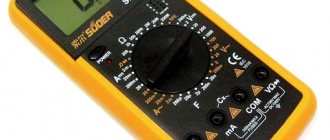
Method No. 3: Checking the mass air flow sensor with a multimeter.
This method works on Bosch sensors with catalog numbers: 0 280 218 004, 0 280 218 037, 0 280 218 116. Turn on the tester in the DC voltage measurement mode, set the measurement limit to 2 Volts.
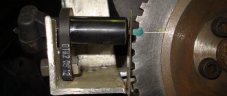
MAF pinout: 1) Yellow (closest to the windshield) - MAF signal input; 2)Gray-white—sensor supply voltage output; 3) Green - sensor grounding output; 4) Pink-black - to the main relay. Wire colors may change, but the pin layout remains the same. Wire colors may change, but the pin layout remains the same.
We turn on the ignition, but do not start the engine. We connect the multimeter with the red probe to the yellow mass flow sensor, and the black one to the green one (to ground). Thus, we measure the voltage between the specified terminals. The tester probes allow you to penetrate through the rubber seals of the connector, along the specified wires, without disturbing their insulation.
The use of needles and other additional connections is not recommended, because they introduce some error in measurements
. We take readings from the multimeter. The output voltage of the new sensor is 0.996…1.01 Volts. During operation, it gradually changes and, as a rule, increases. The greater the value of this voltage, the greater the wear of the mass air flow sensor.
Mass air flow sensor voltage: 1.01…1.02 - good condition of the sensor. 1.02...1.03 - not a bad condition. 1.03…1.04 - the life of the mass air flow sensor is coming to an end. 1.04...1.05 - a dying state, if there are no negative symptoms, then we continue to exploit it. 1.05...and higher - it’s time to replace the mass air flow sensor.
By the way, the same readings can be obtained without a tester, using the on-board computer (group of parameters “voltage from sensors”, Udmrv)
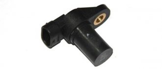
What is your MAF sensor? The first mass air flow sensor was a frequency sensor in the control system from GM. It was also used in “January” of the 4th series. Cars of this configuration did not last long and the frequency sensor was replaced by an analog model HFM-5 from Bosch under number 0280218004.
It is not interchangeable with GM; the connectors and mounting points are completely different. The German sensor is dismountable and consists of two parts - a housing and a measuring element. The latter is secured in the case with two screws with “secret” heads.
Bosch only sells assembled sensors in yellow cardboard packaging.
The third version of the mass air flow sensor is 0 280 218 037 or 037th, as determined by car enthusiasts by the last three digits in their designation. This is a further development of the 004 sensor from Bosch.
Such a sensor is used today on most VAZ cars, including Niva and Chevrolet Niva. Externally, 004 and 037 are almost indistinguishable; you need to navigate by their numbers.
Recently, additional markings have appeared on products: now there are numbers on both the body and the measuring element - they must match.
The main difference is inside the mass air flow sensor. The 037th sensor has a different design of the measuring element, with a characteristic cutout (when purchasing, it makes sense to remove the plug and look inside).
Then a new control system appeared - Bosch M7.9.7, which has its own, 116th mass air flow sensor. It is not interchangeable with the previous ones, although its body is the same.
To avoid confusion, a green circle was first applied to the body. There are numbers on both the body and the measuring element. The latter determines the purpose of this mass air flow sensor.
VAZ 2110 air sensor pinout diagram
- Yellow (closest to the windshield) - mass air flow sensor signal input;
- Gray-white—sensor supply voltage output;
- Green — sensor grounding output;
- Pink-black - to the main relay.
The wire colors may change, but the pin locations remain the same.
Let’s also add that the mass air flow sensor with endings 004, 037, 116 (for Bosch) and 00, 10, 20 (for Pekar) are different in calibration. You can only change it by flashing it.
Types of mass air flow sensors, their design features and operating principle
Three types of VU meters are most widespread:
- Wire or thread.
- Film.
- Volumetric.
In the first two, the operating principle is based on obtaining information about the mass of the air flow by measuring its temperature. The latter may involve two accounting options:
- By changing the position of the slider, driven by a special blade, which is affected by the air flow passing through the device.
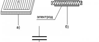
Considering the presence of rubbing mechanisms, the level of reliability of such structures is quite low. This was the main reason for the refusal of car manufacturers from sensors of this type. For reference, here is a simplified example of the design of a volumetric flow meter. Volumetric air flow sensor device - By counting Karman vortices. They are formed if a laminar air flow washes over an obstacle whose edges are quite sharp. The frequency of the vortices breaking off from them is directly related to the speed of air flow passing through the device.
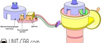
Vortex sensor design (widely used by Mitsubishi Motors)
Legend:
- A – pressure measurement sensor to record the passage of the vortex. That is, the frequency of pressure and vortex formation will be the same, which makes it possible to measure the flow of the air mixture. At the output, using an ADC, the analog signal is converted to digital and transmitted to the ECU.
- B - special tubes that form an air flow similar in properties to laminar.
- C – bypass air ducts.
- D – column with sharp edges on which Karman vortices are formed.
- E – holes used to measure pressure.
- F – direction of air flow.
Connecting the MAF air sensor VAZ 2112
If the mass air flow sensor is operational, then when the engine is running at 900 rpm, the volume of air used will be at least 10 kg per hour. When the speed increases to 2 thousand, this figure will increase to approximately 20 kg. If the volume of air at such speeds drops, the dynamics of the vehicle will also decrease, and accordingly, this will lead to a decrease in gasoline consumption.
If these indicators increase, this will also contribute to an increase in fuel volume. Deviations of the parameter by 2-3 kg should not be allowed, since in this case the operation of the power unit may be incorrect.
Video “Checking the mass air flow sensor using a multimeter”
This video from the “Simple Opinion” channel demonstrates how to check the mass air flow sensor with a multimeter.
0 comments on “After replacing the DMRV stalls. When the MAF sensor is disconnected, the car works "
2) what kind of adsorber transmission?
1 why do you think the reason is in the DMV?
The second question is a masterpiece
2.that’s the question
1. This is how it should be. if it weren’t for stalling.. Then the DMRV is not working
Sergey Kozenkov, formulate the question differently, your comrades will definitely help.
1. When the air flow sensor is removed, the speed increases. That's why it doesn't stall. There are many options. Throttle assembly, rrx, fuel system. What color spark plugs?
Alexey, rkhh, dpdz are new, the spark plugs and ignition coil were installed from another car, still the same, briisk spark plugs
Rinal, no candles by color, filled black or light
Alexey, I need to look, I didn’t take pictures
Rinal, if the fuel is light, then the pressure in the filter rail is low. If they are flooded black, then there is a lot of fuel, which means misfires. Armored wires, wiring. And in general, if the lambda is not wired up, then diagnostics
Alexey, I’ll check it tomorrow and answer, the lambda is sewn up. Thank you
1. Unaccounted air somewhere (suction).
Yes, it’s all T9’s fault. It’s not a problem, it’s pinched. The old owner pressed the phone. What is this for
2. Clamped to prevent air leaks. It is pinched when it is disabled in the firmware, but it’s just not good. You need to find out whether it is actually disabled from a diagnostician. If it is turned off completely, then you can remove everything up to the receiver and remote control, just plug the holes on the receiver and remote control. One tube goes to the gas tank and the other to the remote control.
1 To competently search for solutions to such problems, you need a motor tester and a vacuum gauge, a scanner, as well as an auto diagnostician (a person who has at least read a book about the operating principle of an injection engine) WHAT EXACTLY DO YOU NEED HELP WITH? Find a car diagnostician, help buy a tool, or do you need literature for learning diagnostics?
Sergey, watch the video of the TAZTEAM channel on YouTube, an episode about crankcase gases in tuning. In the middle of the video, he explains how to remove the absorber correctly.
Connection diagram for air flow sensor 2114
A common cause of incorrect operation of the mass air flow sensor is the failure of electronic components, which increases the sensor’s response time to changes in air flow. A working sensor monitors changes at a speed of 0.5 ms, and if it breaks down, the response time increases by 20-30 times. The defect is detected only by recording the operation graph with an oscilloscope. Such a sensor cannot be repaired; it must be replaced with a new one.
Basic faults
There is practically nothing to break in a film sensor, so they are considered “eternal”. The spiral of filament air flow sensors is less reliable, however, these electronic devices cannot be repaired in principle, with the exception of cleaning and replacement. The following symptoms will help determine the malfunction of this particular sensor:
- spontaneous decrease in engine power;
- decreased acceleration dynamics;
- engine not ;
- increase in fuel consumption unjustified by driving style;
- illuminated Check errors;
- change in XX speed in any direction, appearance of jerks;
- The car stalls when changing gears.
When diagnosing a low signal level, the following options are possible:
- the plug fell off;
- the power supply is broken;
- oxidation or loss of mass;
- signal wire break.
Rice. 10 Mechanical damage to the VU meter
Since the electrical device is not repairable, but has a simple design, diagnostics can be performed on your own according to the principle of increasing its complexity.
Replacing the sensor - instructions
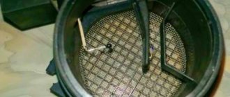
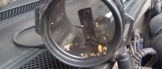
Using a screwdriver, unscrew the clamp of the air intake corrugation at the sensor outlet, pull it off and carefully inspect the internal surfaces of the sensor itself and the corrugation. These surfaces must be dry and clean; traces of condensation and oil are unacceptable. If the air filter is changed rarely, then dirt getting on the sensitive element of the sensor is the most common cause of its breakdown in VAZ cars.
There may be oil in the mass air flow sensor as a result of an increased oil level in the engine crankcase, or the oil sump of the crankcase ventilation system is clogged.
Next, unscrew the 2 screws of the sensor with a 10mm wrench and remove it from the air filter housing. There should be a rubber sealing ring on its front part (at the entrance edge). It prevents unfiltered air from being sucked into the intake tract through the sensor.
If the ring is out of place and stuck somewhere in the air filter housing, then there will be a thin layer of dust on the inlet mesh of the sensor itself. This is the second reason that destroys the mass air flow sensor ahead of time.
Correct assembly should take place in the following sequence: put a sealing rubber band on the sensor, check the sealing skirt, then insert everything together into the filter housing.
This concludes the visual check of the mass air flow sensor at home. You can check its operation 100% only with the help of special equipment in a car service center. For example, using a technique for assessing the oscillogram when the throttle is sharply opened to the cutoff mode (a motor tester is needed), or assessing the oscillogram when the ignition is turned on.
Resuscitation of a damaged air flow sensor is successful in no more than 5% of cases. In extreme cases, you can rinse with ethereal liquid to clean matrices and optics. It will evaporate without a trace. After making sure that there is no more dust or debris in the device, you can dry it thoroughly and put it back in place. Sometimes after such a simple procedure the device will work.
On most foreign cars, a mass air flow sensor was installed until 2000; subsequent generations of models began to be equipped with a pressure controller. Replacing a non-working sensor is simple and can be done on your own without any problems, you just need to buy a mass air flow sensor that matches the ECU firmware version. Its price is around 3,000 rubles, depending on the manufacturer.
Checking and repairing at home
There are eight ways to independently check amplitude and frequency mass flow sensors.
Method No. 1 - disabling the air flow meter
The method consists of disconnecting the sensor from the fuel system of the car and checking the functionality of the system without it. To do this, you need to disconnect the device from the connector and start the engine. Without a mass air flow sensor, the controller receives a signal to switch to emergency operation mode. It prepares the air-fuel mixture only based on the throttle position. If the car moves faster and does not stall, it means that the device is faulty and requires repair or replacement.
Method No. 2 - flashing the electronic control unit
If the standard firmware has been changed, then it is unknown what reaction of the controller is programmed in it in case of an emergency. In this case, you should try to insert a 1mm thick plate under the throttle stop. The turnover should increase. Now you need to pull out the chip from the air flow meter. If the power unit continues to work, then the cause of the malfunction is the firmware.
Method No. 3 - installing a working sensor
Install a known good part and start the engine. If after replacement it begins to work better, the motor does not stall, then replacement or repair of the device is required.
Method No. 4 - visual inspection
To do this, use a Phillips screwdriver to unscrew the clamp holding the air collector corrugation. Then you need to disconnect the corrugation and inspect the internal surfaces of the air collector corrugation and the sensor.
Interchangeability
This issue is quite relevant, especially taking into account the cost of original products from the imported automobile industry. But it’s not so simple here, let’s give an example
In the first production models of the Gorky Automobile Plant, the injection Volgas were equipped with a BOSCH air flow sensor. Somewhat later, imported sensors and controllers replaced domestic products.
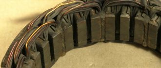
A – imported filament air flow sensor manufactured by Bosh (pbt-gf30) and its domestic analogues B – JSCB “Impuls” and C – APZ
Structurally, these products were practically no different with the exception of several design features, namely:
- The diameter of the wire used in a wirewound thermistor. Bosch products have a diameter of 0.07 mm, and domestic products have a diameter of 0.10 mm.
- The method of fastening the wire differs in the type of welding. For imported sensors this is resistance welding, for domestic products it is laser welding.
- Shape of a thread thermistor. Bosh has a U-shaped geometry, APZ produces devices with a V-shaped thread, and products from JSC Impulse are distinguished by the square shape of the thread suspension.
All the sensors given as an example were interchangeable until the Gorky Automobile Plant switched to film analogues. The reasons for the transition were described above.
Film air flow sensor Siemens for GAZ 31105It makes no sense to give a domestic analogue to the sensor shown in the figure, since outwardly it is practically no different.
It should be noted that when switching from filament devices to film devices, most likely, it will be necessary to change the entire system, namely: the sensor itself, the connecting wire from it to the ECU, and, in fact, the controller itself. In some cases, the control can be adapted (reflashed) to work with another sensor. This problem is due to the fact that most filament flowmeters send analog signals, while film flowmeters send digital signals.